I don't think you're crazy. I think the drawing is showing that you need to remove the plastic pieces protecting the threads on the mounting posts, before you install the back plate. Have you received the box yet? A quick look inside will verify if the threads are covered or exposed.
You are using an out of date browser. It may not display this or other websites correctly.
You should upgrade or use an alternative browser.
You should upgrade or use an alternative browser.
Electric burners - Any builders out there?
- Thread starter CidahMastah
- Start date

Help Support Homebrew Talk:
This site may earn a commission from merchant affiliate
links, including eBay, Amazon, and others.
bruin_ale
Well-Known Member
No, it says to toss the standoff holders into the garbage. Your panel should have had these plastic caps over the four backplate standoffs and the grounding posts. They're trivial, toss 'em and install the backplate.
Good call, it's been awhile since I used mine - but now that you mention it, I do recall tossing the plastic standoff covers.
CidahMastah
Well-Known Member
- Joined
- Nov 12, 2010
- Messages
- 4,201
- Reaction score
- 46
I don't think you're crazy. I think the drawing is showing that you need to remove the plastic pieces protecting the threads on the mounting posts, before you install the back plate. Have you received the box yet? A quick look inside will verify if the threads are covered or exposed.
Ha! one of those things that I probably would have figured out in about... 5 seconds after looking at the box....:cross:
Thanks guys!
CidahMastah
Well-Known Member
- Joined
- Nov 12, 2010
- Messages
- 4,201
- Reaction score
- 46
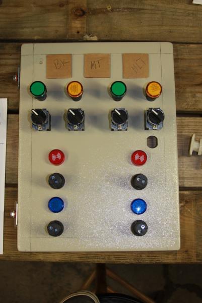
Hey all I just got a couple major pieces to the puzzle in for my ebuild 2.0. Based on the cost of certain parts my design totally changed. Have a quick look and let me know what you think. This is my intended layout.
Notes:
I only have 2 PIDs. With this design I can throw a 3rd in the center down the road without it looking funny. So imagine the MT PID absent for this build (cardboard in the picture). Also, I can add another alarm and pump in the center if I ever bump up to three pumps.
Currently I plan on having the green light represent power to the terminal block on (one for each separate 30amp feed) and orange will be element fired.
Card board represents BK MT and HLT PIDs, respectively.
Oh yeah, the upside down lights are supposed to be on off switches (don't have the rest of them in yet)

CidahMastah
Well-Known Member
- Joined
- Nov 12, 2010
- Messages
- 4,201
- Reaction score
- 46
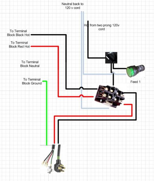
Hey guys need some help. Do the contactors need a a ground? I,e, i am trying to figure out how I am going to power my switches that will activate (turn on) the contactors to send two hots to my terminal block. Can I simply use a 2 prong cord with a hot and a neutral? I was thinking of running a 120 line in to supply power to activate two contactors.
Plan being:
1. run a 2 prong cord with the hot into the contactor coil (switch to control opened or closed)
2. The neutral from the same cord goes into the opposite side of the coil on the contactor.
This way I can use a regular low amperage switch to power the two contactors that will turn on/off the power to each of my two terminal blocks. 1 120 line running into the control panel. Spliced so hots will go to the hot side of each of the two terminal blocks. Splice neutrals and return on the 2 prong plug, from each of the two contactors.
Just a reminder, my set up is using two independent terminal blocks for two independent supplies of 30amps to each side of the panel. I want to control the power feed to each terminal block.

$10.99 ($31.16 / Ounce)
Hornindal Kveik Yeast for Homebrewing - Mead, Cider, Wine, Beer - 10g Packet - Saccharomyces Cerevisiae - Sold by Shadowhive.com
Shadowhive

$53.24
1pc Hose Barb/MFL 1.5" Tri Clamp to Ball Lock Post Liquid Gas Homebrew Kegging Fermentation Parts Brewer Hardware SUS304(Liquid Hose Barb)
Guangshui Weilu You Trading Co., Ltd

$20.94
$29.99
The Brew Your Own Big Book of Clone Recipes: Featuring 300 Homebrew Recipes from Your Favorite Breweries
Amazon.com

$172.35
2 Inch Tri Clamp Keg Manifold With Ball Lock Posts, Pressure Gauge, PRV (0-30 PSI) – Homebrew, Fermentation, Kegging System
wuhanshijiayangzhiyimaoyiyouxiangongsi

$53.24
1pc Hose Barb/MFL 1.5" Tri Clamp to Ball Lock Post Liquid Gas Homebrew Kegging Fermentation Parts Brewer Hardware SUS304(Liquid Hose Barb)
yunchengshiyanhuqucuichendianzishangwuyouxiangongsi

$27.29 ($13.64 / Count)
$41.99 ($21.00 / Count)
2 Pack 1 Gallon Large Fermentation Jars with 3 Airlocks and 2 SCREW Lids(100% Airtight Heavy Duty Lid w Silicone) - Wide Mouth Glass Jars w Scale Mark - Pickle Jars for Sauerkraut, Sourdough Starter
Qianfenie Direct

$22.00 ($623.23 / Ounce)
AMZLMPKNTW Ball Lock Sample Faucet 30cm Reinforced Silicone Hose Secondary Fermentation Homebrew Kegging joyful
无为中南商贸有限公司

$58.16
HUIZHUGS Brewing Equipment Keg Ball Lock Faucet 30cm Reinforced Silicone Hose Secondary Fermentation Homebrew Kegging Brewing Equipment
xiangshuizhenzhanglingfengshop

$7.79 ($7.79 / Count)
Craft A Brew - LalBrew Voss™ - Kveik Ale Yeast - For Craft Lagers - Ingredients for Home Brewing - Beer Making Supplies - (1 Pack)
Craft a Brew

$176.97
1pc Commercial Keg Manifold 2" Tri Clamp,Ball Lock Tapping Head,Pressure Gauge/Adjustable PRV for Kegging,Fermentation Control
hanhanbaihuoxiaoshoudian

$39.22 ($39.22 / Count)
Brewer's Best Home Brew Beer Ingredient Kit - 5 Gallon (Mexican Cerveza)
Amazon.com
![Craft A Brew - Safale S-04 Dry Yeast - Fermentis - English Ale Dry Yeast - For English and American Ales and Hard Apple Ciders - Ingredients for Home Brewing - Beer Making Supplies - [1 Pack]](https://m.media-amazon.com/images/I/41fVGNh6JfL._SL500_.jpg)
$6.95 ($17.38 / Ounce)
$7.47 ($18.68 / Ounce)
Craft A Brew - Safale S-04 Dry Yeast - Fermentis - English Ale Dry Yeast - For English and American Ales and Hard Apple Ciders - Ingredients for Home Brewing - Beer Making Supplies - [1 Pack]
Hobby Homebrew

$33.95
Five Star - 6022b_ - Star San - 32 Ounce - High Foaming Sanitizer
Bridgeview Beer and Wine Supply
bruin_ale
Well-Known Member
Having a hard time following what your plan is, but it sounds weird - running a separate "two-prong" cord to activate the contactors? How is that any different than just taking 1 leg of any of your terminal blocks? They're both 110V right? Branch off one of those inputs, fuse it and run it through your low amp switch and to the contactor coil.
CidahMastah
Well-Known Member
- Joined
- Nov 12, 2010
- Messages
- 4,201
- Reaction score
- 46
Having a hard time following what your plan is, but it sounds weird - running a separate "two-prong" cord to activate the contactors? How is that any different than just taking 1 leg of any of your terminal blocks? They're both 110V right? Branch off one of those inputs, fuse it and run it through your low amp switch and to the contactor coil.
The problem is this switch is supposed to open/close the power to the terminal block. i.e. there wouldn't be any power coming to the terminal block, thus when the switch is activated it would not have any power to send to the contactor to close it.
I can understand your confusion. I would like to use two contactors to control the hot side input (for each phase) to each of my two terminal blocks. The plan being that I want to have a switch that activates the power to the terminal block for each side of the panel. To turn an element on you would need to turn the power switch, and then turn the element switch (Green light and then yellow light).
The issue I am running into is... if there is no power to the terminal block, I can't use a hot from the terminal block to power the contactor (controlled by a switch) to a closed state.
To mitigate this problem I had thought I could run a 120v line in to a switch to solely provide power to activate (close) the contactors that ultimately supply the two hot feeds to the terminal block. That line's sole purpose would be to supply 120 (through a switch) to the contactor for each side of my panel.
Hopefully the image below helps. There would be a 120v light that would be wired on the bottom side of switch (between the switch and the contactor). So when the switch is closed, the light goes on and the terminal block is energized giving power to the panel so PIDs and anything else are now on, or capable of being turned on (element, etc.).
neutral from the 120v light and the contractor would be spliced and joined back into the 120cord returning to teh wall socket.
Does that make sense?
AlteredEgo
Member
CidahMastah, I've been reading your posts on this thread, would you mind if I took out an insurance policy on you?
CidahMastah
Well-Known Member
- Joined
- Nov 12, 2010
- Messages
- 4,201
- Reaction score
- 46
CidahMastah, I've been reading your posts on this thread, would you mind if I took out an insurance policy on you?
Appreciate your contribution and thanks for attempting to troll.
Ironic you saying that though. My system after it was built passed a certified electrician's inspection and has been in safe use for almost a full year. Where is your build?
CidahMastah
Well-Known Member
- Joined
- Nov 12, 2010
- Messages
- 4,201
- Reaction score
- 46
AlteredEgo
Member
I'm relieved to hear this. I'm pleased that you have a sense of humor. My all-electric build is working fine, thank you. An electrician friend certified my set-up before I plugged it in.My system after it was built passed a certified electrician's inspection and has been in safe use for almost a full year. Where is your build?
CidahMastah
Well-Known Member
- Joined
- Nov 12, 2010
- Messages
- 4,201
- Reaction score
- 46
I'm relieved to hear this. I'm pleased that you have a sense of humor. My all-electric build is working fine, thank you. An electrician friend certified my set-up before I plugged it in.
Not sure why you felt you had to take a jab at me. But I really don't care because I would rather ask a bunch of "dumb" questions to fully understand what I am doing before I pretend I understand and hurt myself or others.
To me it is pretty remarkable that I have learned as much as I have and was able to complete the first, and soon to be second major build for this control panel. Coming from a guy who about a year ago was nervous changing wall socket.
If you haven't already purchased your contactors then you could buy 240 volt coil units and just run power from the line in side of the contactor through your switch and activate the coil that way. Or you could bring in a neutral wire with your 240 volt main wiring and use 120 volts to activate the contactor if you already have 120 volt coil units.
It's always good to limit the number of power lines that are feeding into the enclosure because if there are more than a couple there is a chance that you will miss turning one of them off when you go to work inside.
It's always good to limit the number of power lines that are feeding into the enclosure because if there are more than a couple there is a chance that you will miss turning one of them off when you go to work inside.
CidahMastah
Well-Known Member
- Joined
- Nov 12, 2010
- Messages
- 4,201
- Reaction score
- 46
If you haven't already purchased your contactors then you could buy 240 volt coil units and just run power from the line in side of the contactor through your switch and activate the coil that way. Or you could bring in a neutral wire with your 240 volt main wiring and use 120 volts to activate the contactor if you already have 120 volt coil units.
It's always good to limit the number of power lines that are feeding into the enclosure because if there are more than a couple there is a chance that you will miss turning one of them off when you go to work inside.
You touched on my main concern - possible design flaw. While I believe that the way I presented the wiring will work, I dislike having 3 feeds... hmm..
I already have the contractors. Perhaps I could leave one hot always on the panel? and only use one side of the contactor for the second phase.
CidahMastah
Well-Known Member
- Joined
- Nov 12, 2010
- Messages
- 4,201
- Reaction score
- 46
Or you could bring in a neutral wire with your 240 volt main wiring and use 120 volts to activate the contactor if you already have 120 volt coil units.
I think I read this wrong. So are you saying that I could take the neutral from the main feed to power the contactor at the main? Where would I route the neutral side of the the contactor?
The unit I have is a 2 pole x 120v contactor (This same P/N) I was trying to use one contactor for each side of my panel
Ok so I was trying to read back through this thread and catch up on what you finally decided to do. Can you give me a quick refresher on how you decided to feed your garage with power and what you were feeding your panel with. A PM is fine if you want. And just for your knowledge your brother in law is one of my brothers. IBEW 191
CidahMastah
Well-Known Member
- Joined
- Nov 12, 2010
- Messages
- 4,201
- Reaction score
- 46
Ok so I was trying to read back through this thread and catch up on what you finally decided to do. Can you give me a quick refresher on how you decided to feed your garage with power and what you were feeding your panel with. A PM is fine if you want. And just for your knowledge your brother in law is one of my brothers. IBEW 191
Very cool and thanks - PM on the way. He is a good egg and was shocked* when I showed him "what I had been up to".
*not literally shocked haha, pun intended
CidahMastah
Well-Known Member
- Joined
- Nov 12, 2010
- Messages
- 4,201
- Reaction score
- 46
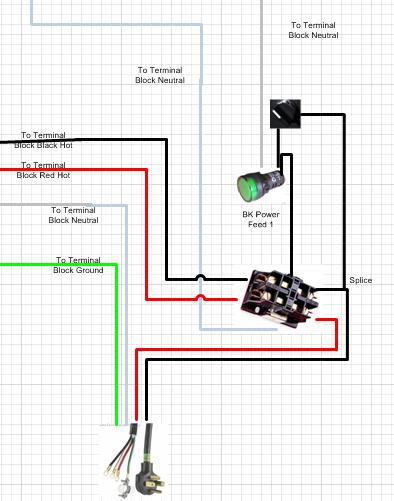
OK as an update, I wanted to post the following wiring for my predicament as listed above. In order to control the main power feed at the contactors for each side this will be the following wiring format. I will replicate this for each side of the build.

CidahMastah
Well-Known Member
- Joined
- Nov 12, 2010
- Messages
- 4,201
- Reaction score
- 46
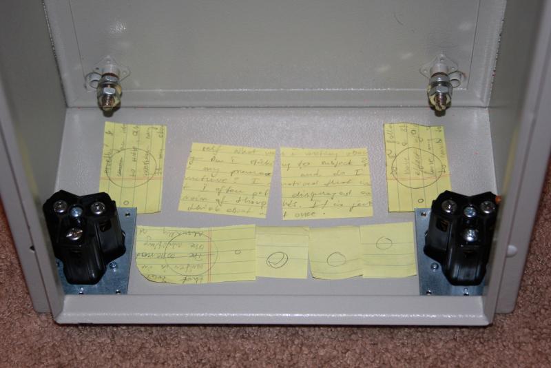
Did a mini mock up of the control panel on a 1/4 inch piece of wood cut to scale of my box. I think this will be what I am going with!
I also mocked up some cutout paper to plan where I am putting my power/probe receptacles
Really glad I did this so now I have a template and am sure the spacing is correct for usability.
(the lady hiding behind the panel)

I also mocked up some cutout paper to plan where I am putting my power/probe receptacles
Really glad I did this so now I have a template and am sure the spacing is correct for usability.
(the lady hiding behind the panel)


Did a mini mock up of the control panel on a 1/4 inch piece of wood cut to scale of my box. I think this will be what I am going with!
I also mocked up some cutout paper to plan where I am putting my power/probe receptacles
Really glad I did this so now I have a template and am sure the spacing is correct for usability.
(the lady hiding behind the panel)
Cidah
Looks good man I will like to see how the rest of the build progresses. What all are you placing at the bottom? sure looks like alot of things for that tight spot, think it will be hard to wire!
CidahMastah
Well-Known Member
- Joined
- Nov 12, 2010
- Messages
- 4,201
- Reaction score
- 46
Cidah
Looks good man I will like to see how the rest of the build progresses. What all are you placing at the bottom? sure looks like alot of things for that tight spot, think it will be hard to wire!
Yeah it is a bit tight!
I need to have space for two of those nema flange receptacles (one for eace of my two sides on the panel). Then I have space for 3 probes (3xlr panel mount). The 30 amp 3wire outlets you see in the pic will be there too (HLT and BK). Right now I have put in 3 120v 20amp plugs too. Those would be for at least 2 pumps. I have been toying with the idea of the third and last plug to be power to an HLT stirring motor, but still have not decided.
So lots of stuff! If I have to lose a plug it will be 1 of the 120v. However I am not cutting a thing until I get all the actual hardware in my hand to be sure it doesn't obstruct anything in my layout. Patience patience!
Of course I had to go for a 60amp panel that was redundant (essentially cramming the guts of 2 panels into one). Worse yet, I went for a 16x12x8 box vs. the 16x16x8. But I know it will all fit!
CidahMastah
Well-Known Member
- Joined
- Nov 12, 2010
- Messages
- 4,201
- Reaction score
- 46
A couple more pictures to add. Last weekend I received my ebay heat sink so I cut out the heat sink section on the box and perfect fit! Then I tapped it and the main board where the terminal blocks and contactors will be located.
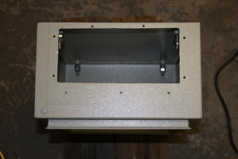
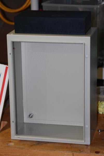
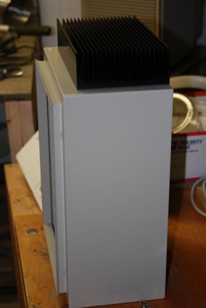


CidahMastah
Well-Known Member
- Joined
- Nov 12, 2010
- Messages
- 4,201
- Reaction score
- 46
I am considering adding a 3rd PID and was looking at the Auberins SYL-2352P so I could ad ramp functionality. Does anybody have any personal experience with this PID?
I am debating if a ramp-able PID is something I will really need/use in the future. If it is a worth while investment.
I am debating if a ramp-able PID is something I will really need/use in the future. If it is a worth while investment.
Well originally this all started as just looking for a way to cheaply boil my wort via electric. It seems like, with all the nifty gadgets, it my grow into a much more automated set up. If you are buying the PID you might as well think about the longterm set up, and using it for all aspects of the process. The idea of monitoring the mash is especially appealing.
This is how it starts

CidahMastah
Well-Known Member
- Joined
- Nov 12, 2010
- Messages
- 4,201
- Reaction score
- 46
CidahMastah
Well-Known Member
- Joined
- Nov 12, 2010
- Messages
- 4,201
- Reaction score
- 46
Mad some progress. I am ready for paint!
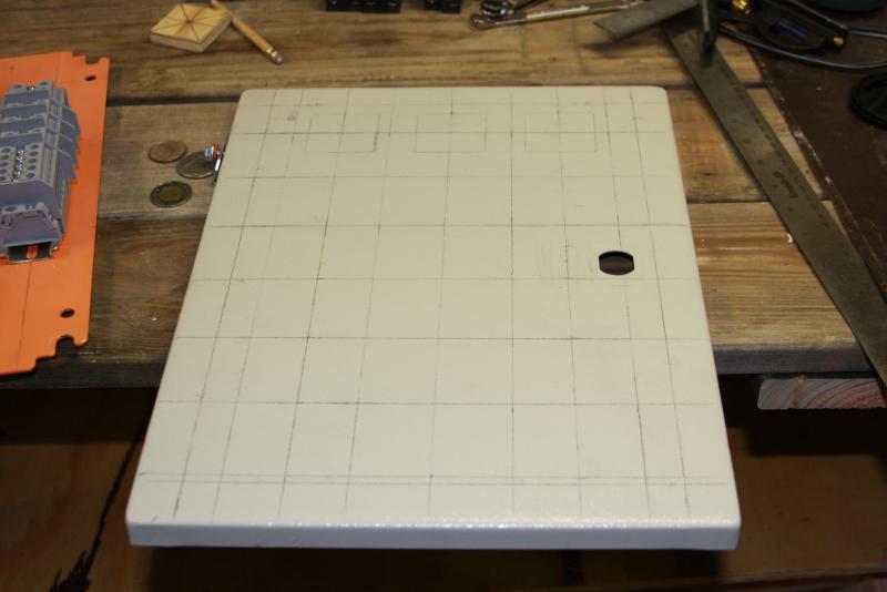
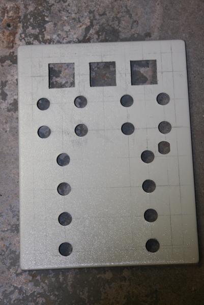
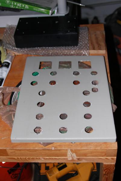
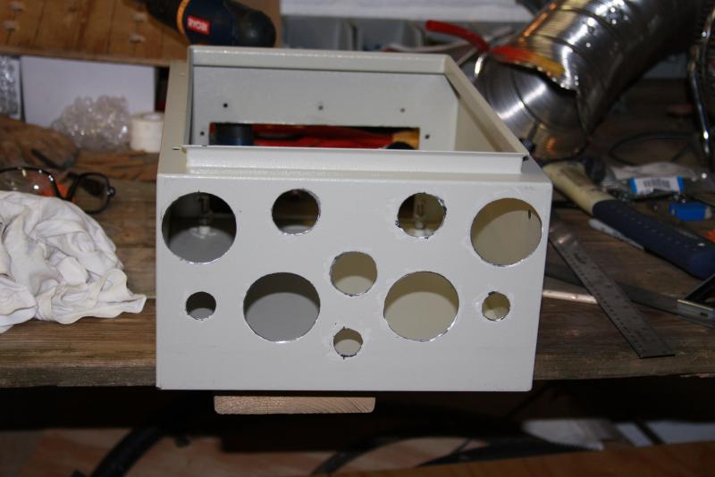


CidahMastah
Well-Known Member
- Joined
- Nov 12, 2010
- Messages
- 4,201
- Reaction score
- 46
and some more. Starting to look like something. Did some deburring as well
I also drilled and taped my heat sink, so that is all set for action to. Can't wait to get the the paint, then wiring this week
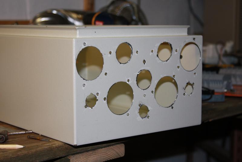
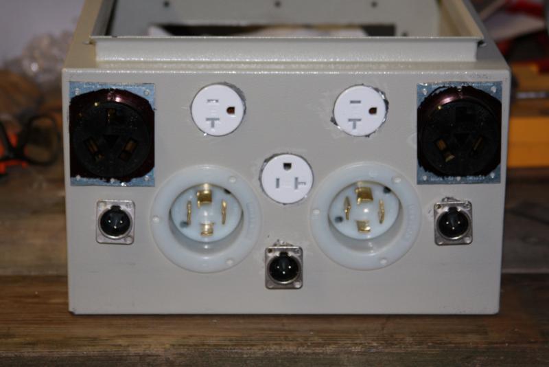
I also drilled and taped my heat sink, so that is all set for action to. Can't wait to get the the paint, then wiring this week


looking good Cidah I think you have a lot going on in that small area!!
CidahMastah
Well-Known Member
- Joined
- Nov 12, 2010
- Messages
- 4,201
- Reaction score
- 46
looking good Cidah I think you have a lot going on in that small area!!
I measured all the stuff out, then checked clearances with measure, then with actual parts in place and looks like I will have plenty of space. The space will require me to keep things neatly wired, but that is part of the beauty of the electrical rigs. Nice neat and secured wiring!
Can't wait to settle up the painting and then to get the hardware in place for wiring. Still waiting on my switches from china though.... suckers. now they are past due and it would really suck to have them refund me with no switches in hand. Hopefully they come in this week right after I get the painting done.
the cool part about the receptacles is that with the current set up I will have the ability to have 3 120 outlets. 2 are spoken for with pumps with one unclaimed. This will either be for a third pump down the road, a ventilation hood fan or a mechanical stirrer for the HLT when I complete my eherms.
Similar threads
- Replies
- 9
- Views
- 656
- Replies
- 11
- Views
- 969
Latest posts
-
-
-
-
-
-
-
I just poured 42 bottles of HB Dunkelweizen down the drain
- Latest: Hoochin'Fool
-


