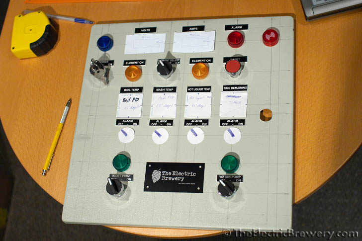
• Please visit and share your knowledge at our sister communities:
  • If you have not, please join our official Homebrewing Facebook Group!

    Homebrewing Facebook Group

Electric brewery plans - need help

Homebrew Talk

Help Support Homebrew Talk:

This site may earn a commission from merchant affiliate links, including eBay, Amazon, and others.
kingbrew said:
do you think you needed the 10" deep enclosure or could you have gotten away with 6 or 8 inches deep?

A lot of people use 8" deep enclosures with no problem. Some people have used 6" but you really have to plan out where you put stuff on the back plate so they don't hit the switches, pids, etc. I went 8" and wouldn't go smaller
 
A lot of people use 8" deep enclosures with no problem. Some people have used 6" but you really have to plan out where you put stuff on the back plate so they don't hit the switches, pids, etc. I went 8" and wouldn't go smaller
+1 to this. 8" deep is what I used. Some of the door components are very close to the backplate components but there's room. 6" means you have to plan ahead and make sure it'll all fit before you buy the enclosure.

That said, you should always plan ahead anyway and lay everything out to make sure it'll not only fit on the inside for wiring but also work well on the outside and leave enough room for labels/tags and what not.

I played around a long time with my layout before finding one I liked:

IMG_0797.jpg


Don't be in a hurry. Lay things out, go through your brewday pretening to flick switches and press buttons. See how it feels.

Kal

Ayup. +1

I 3D modeled my enclosure and its components before making any cuts. I made my drawings from those models, which made it easy to CNC the holes and cutouts. I knew I had some room to work with, but I wasn't taking any chances, and I had access to the software. With a shallower box, planning is a must.

:off: just got around to listening to the BN podcast in which you were a guest, Kal. Thought you did very well for how many times you were interrupted! :mug:
 
TB,

Hey man I just wanted to let you know I finally completed my build about a week ago, and brewed on it for the first time yesterday. Still have a few kinks to work out but overall very happy, thanks for all your input and assistance. Happy Brewing!!!
 
TB,

Hey man I just wanted to let you know I finally completed my build about a week ago, and brewed on it for the first time yesterday. Still have a few kinks to work out but overall very happy, thanks for all your input and assistance. Happy Brewing!!!

Great! I'm glad I could help! You will love electric brewing.

:mug:
 
You might be able to get away with 8", but unless you use all DIN components, I wouldn't go much less than that. Just a recommendation. It makes it easier to arrange and wire the components, and helps with thermal management. (My control panel is purely natural convection.)

A lot of people use 8" deep enclosures with no problem. Some people have used 6" but you really have to plan out where you put stuff on the back plate so they don't hit the switches, pids, etc. I went 8" and wouldn't go smaller

+1 to this. 8" deep is what I used. Some of the door components are very close to the backplate components but there's room. 6" means you have to plan ahead and make sure it'll all fit before you buy the enclosure.

That said, you should always plan ahead anyway and lay everything out to make sure it'll not only fit on the inside for wiring but also work well on the outside and leave enough room for labels/tags and what not.

I played around a long time with my layout before finding one I liked:

Don't be in a hurry. Lay things out, go through your brewday pretening to flick switches and press buttons. See how it feels.

Kal


Awesome, thanks. Just wanted to be sure before I dropped $120+ on a steel box. Being a welder I thought about making one but after pricing out the steel, hinge, backplate, lock and waterproofing seal it would be about the same. I like the idea of having plenty of room and since I'm copying Timber_Brew's control box internals I'm gonna go with the Hammond EJ161410 box.
 
Hi, first, let me say that your built really inspired me. I read the entire thread :cross: , and am now ready to try to build something similar. BTW, big thanks to P-J for his easy to understand wiring diagrams.

I am now looking for and buying parts for the project. Searching for th momentary kill switch, I can't find which one is needed, since there are a lot of different ones. For instance, 600V 10A 1 N/C 1 N/O, 380V 10A 1 N/C 1 N/O, 415V 10A (you get the picture...)

Sooo, which one is needed in your particular system ?

Thanks
 
Great ! Thanks guys.

Quick question for P-J, about the small fuses. Are all the 1A fuses fast-blow or just the ones protecting the PIDs ?
 
Great ! Thanks guys.

Quick question for P-J, about the small fuses. Are all the 1A fuses fast-blow or just the ones protecting the PIDs ?
Yes. They are all fast-blow. The only time you would need to have a 'slow-blow' fuse is with an inductive load that has a higher than normal initial current draw that is close to the circuit rating.

Hope this makes sense and helps you.

P-J
 
Yes. They are all fast-blow. The only time you would need to have a 'slow-blow' fuse is with an inductive load that has a higher than normal initial current draw that is close to the circuit rating.

Hope this makes sense and helps you.

P-J

Yes it does :mug:

I might have more question along the way... Thanks again guys
 
What kind of connector do you use for probe wire? I imagine that is possible put a connector that be able remove the probe wire when you finish you brew day.

Thanks,

Fabiano
 
What kind of connector do you use for probe wire? I imagine that is possible put a connector that be able remove the probe wire when you finish you brew day.

Thanks,

Fabiano

I used these panel mount connectors from Auber Instruments. It requires a steady hand to solder these, but with proper tools and some patience, it's a great connector.

RTDconnector2.jpg
 
Hi guys, still gathering the parts before I begin buiding this system.

I want to adapt it with a HERMS coil in the HLT. So what I'm wondering is do I need a third PID to read the wort temp exiting from the mash tun to the HERMS coil ? If so, how would that change the wiring diagram ?
My guess would be that the first PID reads a probe in the HLT and contols its element, the 2nd PID would read the probe placed at the output of the mash tun, without controling any element, just to know when the desired wort temp is reached, and the 3rd one to read and control the temperature of the BK.

Am I right ?
 
Hi guys, still gathering the parts before I begin buiding this system.


I want to adapt it with a HERMS coil in the HLT. So what I'm wondering is do I need a third PID to read the wort temp exiting from the mash tun to the HERMS coil ? If so, how would that change the wiring diagram ?

My guess would be that the first PID reads a probe in the HLT and contols its element, the 2nd PID would read the probe placed at the output of the mash tun, without controling any element, just to know when the desired wort temp is reached, and the 3rd one to read and control the temperature of the BK.


Am I right ?


That's how a lot of people have done it and is how the system at theelectricbrewery.com is setup. It works well.
 
OK. How this kind of setup would change the wiring diagram presented in the first page of this thread ?

How many elements do you plan to have running simultaneously?

I only have a single 20A, 240V circuit so I only run one element at a time...

You really only need one PID if doing it that way, for the HLT/HERMS/RIMS.

Once you complete your mash/sparge & transfer all to the brew kettle, you power up the BK element for the boil. I just unplug my HLT/HERMS element & plug in the BK element.

What I have found to work best is a single PID fed via a probe on the output of the HERMS prior to returning back to the MLT. I also have a dial temp gauge on my HLT water & the MLT. That way I can compare all three temps relative to one another. They are typically always within one degree of each other. I originally tried to measure the mash temp coming out of the MLT on it's way back to the HERMS but it resulted in much wider temp variance between the MLT & HLT.

I also have a probe on my BK but you don't have to have one for the sake of the boil.. Just set the PID to manual mode. 212 degrees & control the boil via manipulating the duty cycle output of the PID.
 
How many elements do you plan to have running simultaneously ?

In fact I am planning to build the same system that is discussed in this thread, with the same electrical input. Almost all the parts needed have arrived. But to answer your question, I think it would be one at the time, but maybe the OP could tell us more about it ?
 
How many elements do you plan to have running simultaneously?

I only have a single 20A, 240V circuit so I only run one element at a time...

You really only need one PID if doing it that way, for the HLT/HERMS/RIMS.

Once you complete your mash/sparge & transfer all to the brew kettle, you power up the BK element for the boil. I just unplug my HLT/HERMS element & plug in the BK element.

What I have found to work best is a single PID fed via a probe on the output of the HERMS prior to returning back to the MLT. I also have a dial temp gauge on my HLT water & the MLT. That way I can compare all three temps relative to one another. They are typically always within one degree of each other. I originally tried to measure the mash temp coming out of the MLT on it's way back to the HERMS but it resulted in much wider temp variance between the MLT & HLT.

I also have a probe on my BK but you don't have to have one for the sake of the boil.. Just set the PID to manual mode. 212 degrees & control the boil via manipulating the duty cycle output of the PID.
I agree that the temp probe on the output of the herms coil is a better idea...I had mine at the ouput of my MT and the temps were always wandering around... People should look at a herms like a rims... you put the sensor right at the output to have tighter control.

20a 240v line? what size element are you running... Thats close even with a 4500w element that draws about 18amps. with pids and such on the same circuit your lucky your breaker does pop after it heats up... (unless you have a smaller element?)
 
How many elements do you plan to have running simultaneously?

I only have a single 20A, 240V circuit so I only run one element at a time...

You really only need one PID if doing it that way, for the HLT/HERMS/RIMS.

Once you complete your mash/sparge & transfer all to the brew kettle, you power up the BK element for the boil. I just unplug my HLT/HERMS element & plug in the BK element.

What I have found to work best is a single PID fed via a probe on the output of the HERMS prior to returning back to the MLT. I also have a dial temp gauge on my HLT water & the MLT. That way I can compare all three temps relative to one another. They are typically always within one degree of each other. I originally tried to measure the mash temp coming out of the MLT on it's way back to the HERMS but it resulted in much wider temp variance between the MLT & HLT.

I also have a probe on my BK but you don't have to have one for the sake of the boil.. Just set the PID to manual mode. 212 degrees & control the boil via manipulating the duty cycle output of the PID.

In fact I am planning to build the same system that is discussed in this thread, with the same electrical input. Almost all the parts needed have arrived. But to answer your question, I think it would be one at the time, but maybe the OP could tell us more about it ?
Not to answer for the OP, who clearly has a better handle on this than I do, but I think he's running 50a, which will support running two elements simultaneously, if he wishes. The jump from 30 to 50 wasn't much, price wise. If your electrical panel can handle that without maxing out, I'd do 50. That's what I am doing after a lot of discussion with the person building my Brumatic panel and my electrician. 50a only allows me to really run back to back batches, if I choose. I suppose you can even continue to heat water in your HLT while you boil so you can run it through the system for cleanup. That was something I figure I may be doing.

Speaking to Alex, who builds the Brumatic panels, a PID on the BK is not necessary, but could be nice to have. He said that I can set it a few degrees under boil temp and walk away. I wouldn't be far, but knowing I don't have to watch a kettle boil is a nice idea. Then I swap to manual and just let it rip. The cost was negligible, so I'm running with it.

OP, I appreciate the detail you have gone into here. My hang up right now seem to be kettles and how many ports I need/want. There is so much to think about. Thankfully, I'm not doing the electrical or I'd be a wreck...and probably light my house on fire!
 
I agree that the temp probe on the output of the herms coil is a better idea...I had mine at the ouput of my MT and the temps were always wandering around... People should look at a herms like a rims... you put the sensor right at the output to have tighter control.

20a 240v line? what size element are you running... Thats close even with a 4500w element that draws about 18amps. with pids and such on the same circuit your lucky your breaker does pop after it heats up... (unless you have a smaller element?)

4000 on the HLT (high density), 4500 on the boil (ULWD).

True, it's close. A dedicated circuit. The PID & pump pull very little amperage. It works.
 
I use a 30A line and run one 4500w as well as my 1000w rims heater simultaneously with DC pumps and such and still only draw under 25 amps...
 
Hi guys, still gathering the parts before I begin buiding this system.

I want to adapt it with a HERMS coil in the HLT. So what I'm wondering is do I need a third PID to read the wort temp exiting from the mash tun to the HERMS coil ? If so, how would that change the wiring diagram ?
My guess would be that the first PID reads a probe in the HLT and contols its element, the 2nd PID would read the probe placed at the output of the mash tun, without controling any element, just to know when the desired wort temp is reached, and the 3rd one to read and control the temperature of the BK.

Am I right ?

That's almost exactly how this system is set up. I don't use a PID to read the MLT mash temp, instead I use 2 Blichmann Thermometers mounted on the front of the MLT.
 
You can get these with the wire already soldered. FYI

They are typically included when you buy a probe..

It doesn't quite work like that... I wanted to add a protective sleeve on the external (outside the panel) RTD wire, which requires you to remove the panel connector in question then solder the wires back on after the sleeve is added. Besides that, you also need to solder the internal RTD wires from the PID to the panel connector, which I added a grounded shield too which also requires you to have disconnected RTD wires to apply. Even without the internal shielding, you will have to solder the internal wires to the panel connector.
 
Not to answer for the OP, who clearly has a better handle on this than I do, but I think he's running 50a, which will support running two elements simultaneously, if he wishes. The jump from 30 to 50 wasn't much, price wise. If your electrical panel can handle that without maxing out, I'd do 50. That's what I am doing after a lot of discussion with the person building my Brumatic panel and my electrician. 50a only allows me to really run back to back batches, if I choose. I suppose you can even continue to heat water in your HLT while you boil so you can run it through the system for cleanup. That was something I figure I may be doing.

Indeed my system is 50A supply and I do run both elements at a time every time I brew. It's handy for heating both strike and HEX water simultaneously, maintaining HEX water temp while applying heat to the wort in the kettle as I sparge, and also heating up cleaning water as I boil.

Speaking to Alex, who builds the Brumatic panels, a PID on the BK is not necessary, but could be nice to have. He said that I can set it a few degrees under boil temp and walk away. I wouldn't be far, but knowing I don't have to watch a kettle boil is a nice idea. Then I swap to manual and just let it rip. The cost was negligible, so I'm running with it.

One nice thing about having a PID on the kettle is that you can set a temp for the wort to sit if you're steeping an ingredient that needs to be at a certain temp other than boil. For example, I've done some pale and IPA brews where I steep some whirlpool hops at 165F for 20-30 minutes before cooling and knocking out the rest of the way. I also steep my coffee grounds for coffee beers after the boil at 203F for 5 minutes (per the recommended temp and duration from the National Coffee Association).

OP, I appreciate the detail you have gone into here. My hang up right now seem to be kettles and how many ports I need/want. There is so much to think about. Thankfully, I'm not doing the electrical or I'd be a wreck...and probably light my house on fire!

I'm glad that my thread has been of some help. I would do a few things differently the second time around, but for the most part, this functions awesome, is a pleasure to brew with, and has produced some award winning beer!

Cheers,
TB
 
4000 on the HLT (high density), 4500 on the boil (ULWD).

True, it's close. A dedicated circuit. The PID & pump pull very little amperage. It works.

I use a 5500W element in my HLT, and a 4500W element in my BK. I run both at the same time every single batch. A dedicated 50A circuit will handle this just fine, even with pumps, PIDs, and lighted switches (which, like you say, don't draw much current).
 
Back
Top