1. I'm not sure what kind of terminal blocks to get, and where to get them. I've looked on
www.digikey.com and
www.automation.com, among others, but there are several choices and I want to make sure I don't have to order anything more than once, or worse yet, put the wrong thing in my CP and fry something (or someone).
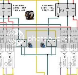
For what it's worth, I used DIN rail mounted distribution blocks. They are modular so you can pretty much add as many as you want and they were not very expensive. My stuff was all rated for 50A and 240V, so cheaper things might be available, but it was still pretty damn cheap to get the 50A stuff.
Links to the modular power distribution stuff at mouser.com are in this post:
https://www.homebrewtalk.com/f51/my-herms-build-ready-criticism-173077/#post2003768
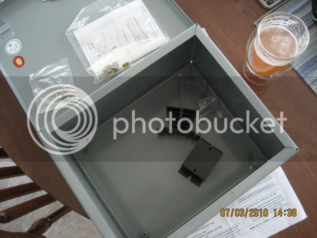
4. What's the best way to cut the square holes in the enclosure panel for the PIDs? I've got a 22.5 mm knock out punch for the switches, but the square knock outs go for around $400. Is it time to invest in a Dremel? What methods have you heard/seen/done?
HA HA HA!
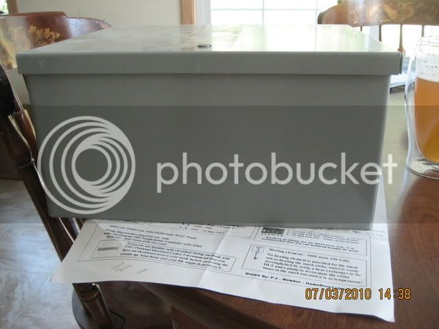
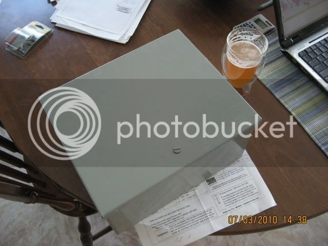
What kind of enclosure are you buying? Plastic? Steel? The material for the enclosure makes a WORLD of difference when it comes to cutting holes!
I snagged a pretty good sized 12 gauge steel enclosure for a BITCHIN' price on ebay and was pretty proud of myself. But then.... I had to cut lots of small rectangles in it because I bought rectangular rocker switches. An, of course, the PID needed a big square cut for it, too.
Cutting those holes was a royal PITA. Drilling round holes was no problem at all. My cheap-o cordless drill was able to do it easily, I just had to take a couple steps with increasing bit sizes to get large holes, but it was still pretty easy.
I bought a dremel thinking I could use it for the squares and rectangles.
NOPE.
It was slow slow slooooooooooooow going, the dremel would get HOT, the battery would have to be recharged often, and I was going through the little cutting disks rapidly. I ended up tossing the dremel to the side completely.
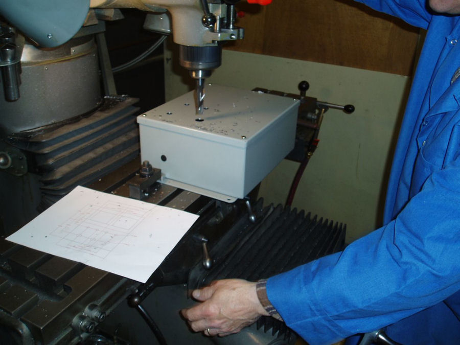
I took a drill bit and went around the whole outline of the hole I wanted to cut drilling many holes very close together. Then I took a tungsten carbide cutting bit that was meant for the dremel and put it in my old plug-in drill and used that to "connect the dots". Then I used a dremel grinding stone (installed in my drill) to grind off the shark tooth shaped pieces of metal that were left around the edges, and then finally had to hand file the edges to get them clean and large enough to slide my components into.
My bitching and moaning can be found here:
https://www.homebrewtalk.com/f51/control-box-enclosures-some-tips-anyone-considering-168536/
If your enclosure is plastic, then a dremel will rip through it like butter. If your enclosure is steel, the thickness of it could make your life difficult.
I spent many many nights in a row out in the garage drilling, grinding, and filing holes in my steel box. In retrospect, I think I would have been happier and saved my self hours of work by just taking a jigsaw and cutting out almost the whole front of the box (one LARGE window) and then using the company Front Panel Express (link is in this thread:
https://www.homebrewtalk.com/f51/control-panel-labeling-give-us-some-ideas-159796/) to layout a sweet looking panel on a sheet of aluminum with text labels on everything, and then paying $50 for that company to punch, cut and engrave the thing and send it to me. I could have just installed it on my box with a few screws.
More expensive for sure, but when I think about the pain I went through....
If I ever decide to make enough changes to my system that I need to reorganize the panel, I am going to do exactly what I described. Cut the whole front of the panel off and hire those guys to make me a nice one.

")


![Craft A Brew - Safale BE-256 Yeast - Fermentis - Belgian Ale Dry Yeast - For Belgian & Strong Ales - Ingredients for Home Brewing - Beer Making Supplies - [3 Pack]](https://m.media-amazon.com/images/I/51bcKEwQmWL._SL500_.jpg)