• Please visit and share your knowledge at our sister communities:
  • If you have not, please join our official Homebrewing Facebook Group!

    Homebrewing Facebook Group

Electric brewery plans - need help

Homebrew Talk

Help Support Homebrew Talk:

This site may earn a commission from merchant affiliate links, including eBay, Amazon, and others.
As for two 5500W elements... 5500W is overkill for a HLT. You CAN use it, but if plan to run both 5500W elements at the same time, you're going to be sucking in 46A. You will probably have issues supplying all of that with a 50A circuit.

If you only want to run one element at a time, you'll be fine. But... 5500W for the HLT isn't really necessary.

What would you recommend for the HLT? 4500? 4000? Would ULD still be a good idea for HLT? I was thinking I would use ULD for both BK and HLT for a bit of protection against dry fire damage.
 
Tiber_Brew,

I spent a little time tonight and reworked the drawing to reflect some of the things that you are dealing with. It now shows the PIDs that you are using:


(Click on the image to see a full scale picture)

Please let me know of any other changes that you would like to see.

EDIT: By the way - the large image is setup and formatted to print on a 11" X 17" sheet.

Thanks for redrawing that PJ. There are just a few things to point out that are different from what I now have in mind.

1. The SSRs I'm using are double pole. Both legs of the element will be switched by one SSR. This is true for both the BK and the HLT.

2. I don't, as of yet, plan on having separate switches for the PID power. I'm just letting those power up when I plug the CP in. Unless, of course, there's a reason you would recommend such a thing. I'm sure it's cheap to wire in just a couple more toggles.

3. Can you show how I would wire in contactors for the elements as Walker and SweetSounds mentioned? I'm very interested in doing that.

Thanks for being a big help PJ. You're pretty good with those diagrams. I tried mocking some ideas up on MS Visio, but gave up after a while. I like yours better. (I can design aerospace avionics that won't overheat in flight, but drawing electrical schematics - no thanks.)
 
Sorry for crowding the thread....but one more tangential question:

What are your guys' thoughts on using the universal PID or fuzzy logic PID from Auber Instruments? It seems to be only about $4 difference. I'm only using the PIDs to reach and maintain strike water and lauter water temps, and for ramping up a boil and maintaining a boil.

I went ahead and assumed that the universal PIDs were sufficient for both the BK and HLT. Thoughts?

universal PID (Auber)

fuzzy logic PID (Auber)

TiberPIDlogicisn'ttheonlythingfuzzynowBrew
 
Thanks for putting all this information out there, I've been studying other threads, Walker, Sweetsounds and a few others, but it's all starting to come together for me in this one. This diagram is dead on what I need minus the HLT since I'm going two vessel.

I have officially wasted a lot of time at work and home reading and re-reading this information, and will likely waste much more. If only my ingredients arrived today I wouldn't have to read about beer all weekend and I could have brewed some.

You're lucky your employer doesn't block this awesome site. My Big Brothers in board rooms don't think it's moral for me to surf "alcohol" sites at work. Can't say I have a legitimate argument, but I'd really like to poke in during a break at work here and there.

TB
 
Thanks for redrawing that PJ. There are just a few things to point out that are different from what I now have in mind.

1. The SSRs I'm using are double pole. Both legs of the element will be switched by one SSR. This is true for both the BK and the HLT.

2. I don't, as of yet, plan on having separate switches for the PID power. I'm just letting those power up when I plug the CP in. Unless, of course, there's a reason you would recommend such a thing. I'm sure it's cheap to wire in just a couple more toggles.

3. Can you show how I would wire in contactors for the elements as Walker and SweetSounds mentioned? I'm very interested in doing that.

Thanks for being a big help PJ. You're pretty good with those diagrams. I tried mocking some ideas up on MS Visio, but gave up after a while. I like yours better. (I can design aerospace avionics that won't overheat in flight, but drawing electrical schematics - no thanks.)

Give me a day and I'll do my best to put it together for you.

Re: PID power. I think it's a good idea to be able to power them down without pulling the plug. Think about it.

Question - Do you have a web link for the specific SSR that you want to use? I'd like to see the item and its connection layout.

How about the contactors? Need to know the rating on the ones you intend to use. (Coil voltage? Size? et.al.)

You got the plan, let me draw it out. (I'll also judge for safety. I have a strong background in electrical work. Originally went through trade school in 1957. AND that was only the beginning.! You betcha.. I'm older than rocks. :rolleyes: )

Keep me posted and lets get er done.
 
You're lucky your employer doesn't block this awesome site. My Big Brothers in board rooms don't think it's moral for me to surf "alcohol" sites at work. Can't say I have a legitimate argument, but I'd really like to poke in during a break at work here and there.

TB

:D
I'm the guy that runs the firewalls and perimeter networks... If they try to block it on me, I'll just add a policy that says my PC can still get access to HBT! I love my job...

:ban:
 
Give me a day and I'll do my best to put it together for you.
I appreciate it, PJ!

Re: PID power. I think it's a good idea to be able to power them down without pulling the plug. Think about it.
Is that to protect it from power surges at plug in?

Question - Do you have a web link for the specific SSR that you want to use? I'd like to see the item and its connection layout.
Sure do. Here are the SSRs from Tyco. You can get the datasheet from that site too.

How about the contactors? Need to know the rating on the ones you intend to use. (Coil voltage? Size? et.al.)
Um...Walker? SweetSounds? I'm sort of at a loss here. I wish I knew what to tell you here, PJ. Perhaps our friends will chime in soon to fill in the blanks.

You got the plan, let me draw it out. (I'll also judge for safety. I have a strong background in electrical work. Originally went through trade school in 1957. AND that was only the beginning.! You betcha.. I'm older than rocks. :rolleyes: )

Keep me posted and lets get er done.
Hey, sounds great! Wish I could return the favor. Let me know if you need to interpret a GD&T engineering drawing or improve thermal management in aerospace avionics! (Or if you're in Michigan's UP and want a beer!)

TB
 
:D
I'm the guy that runs the firewalls and perimeter networks... If they try to block it on me, I'll just add a policy that says my PC can still get access to HBT! I love my job...

:ban:

We are to small to have an official IT guy and bother with blocking sites. Good news is even the Military hasn't blocked it yet, so I've been told.
 
You're lucky your employer doesn't block this awesome site. My Big Brothers in board rooms don't think it's moral for me to surf "alcohol" sites at work. Can't say I have a legitimate argument, but I'd really like to poke in during a break at work here and there.

TB

:off: You could try a proxy. If they block one of them, simply switch to another. I used to do this all the time at my last job :D (and no, I wasn't fired).

http://www.publicproxyservers.com/
 
We're already on a proxy. There's no chance of surfing this site. They even block cached sites. Trust me, this corporate giant has thought of everything to keep us productive. I guess it worked.

Anyway, back on topic... :D

TB
 
Tiber_Brew,

Here is latest diagram. It incorporates SSRDs (Solid State Relay Dual) and contactors for element control and disconnect.


As usual - Click on the image for a full scale drawing.
The full sacle image is set up for printing on a 11" X 17" sheet of paper.

Please let me know your thoughts.
 
What would you recommend for the HLT? 4500? 4000? Would ULD still be a good idea for HLT? I was thinking I would use ULD for both BK and HLT for a bit of protection against dry fire damage.

Not an expert here, but I would think that you could get away with something like 4000W, maybe even smaller, in the HLT. Like I said before, 5500W can be used, but you'll likely not be able to run your BK element and HLT element at the same time on a 50A circuit.

If you want to be able to run them at the same time, you're probably better off going with something no more like 3500W or smaller in size.

Regarding watt density: high watt density would not be a problem in your HLT since the only thing in there will be water.

However, as for the dry-firing issue... High watt density, low watt density, ultra-low watt density; those things really don't have anything to do with whether dry-firing is going to be a problem or not. If you want protection from dry-firing, you will need to specifically get an element that claims it can handle dry-firing.
 
Oh..... forgot to add...

if you do not want to be able to run the HLT and BK elements at the same time, then you can save some money and have your system built using one SSR, one PID, and two contactors.

The output of the SSR could feed to both of the contactors, and you could use a three-way selector to engage the BK contactor or the HLT contactor or have it in an "OFF" position.

Schematic snippet:
oneSSR_twoContactors.jpg
 
Tiber_Brew,

Here is latest diagram. It incorporates SSRDs (Solid State Relay Dual) and contactors for element control and disconnect.


As usual - Click on the image for a full scale drawing.
The full sacle image is set up for printing on a 11" X 17" sheet of paper.

Please let me know your thoughts.

That looks great PJ! That's exactly what I'm looking for. Thanks a lot for your help; it's much appreciated!

Anyone else have any comments? I think I will go with this wiring diagram.

TB
 
Not an expert here, but I would think that you could get away with something like 4000W, maybe even smaller, in the HLT. Like I said before, 5500W can be used, but you'll likely not be able to run your BK element and HLT element at the same time on a 50A circuit.
There might be some overlap during the tail end of the sparge, but I don't anticipate drawing full power from both elements at any point of the brew session. I think I'll stick with the 5500W element, or perhaps get a 4500W.

If you want to be able to run them at the same time, you're probably better off going with something no more like 3500W or smaller in size.

Regarding watt density: high watt density would not be a problem in your HLT since the only thing in there will be water.

However, as for the dry-firing issue... High watt density, low watt density, ultra-low watt density; those things really don't have anything to do with whether dry-firing is going to be a problem or not. If you want protection from dry-firing, you will need to specifically get an element that claims it can handle dry-firing.

I have read that most ULD elements will withstand dry fire. I don't plan on testing that, but you never know - accidents can happen.

Oh..... forgot to add...

if you do not want to be able to run the HLT and BK elements at the same time, then you can save some money and have your system built using one SSR, one PID, and two contactors.

The output of the SSR could feed to both of the contactors, and you could use a three-way selector to engage the BK contactor or the HLT contactor or have it in an "OFF" position.

Schematic snippet:
oneSSR_twoContactors.jpg

That makes sense, but I think I'll stick with what I got from PJ. I'd like to have the ability to run both on an overlap, even if I don't always do that. Thanks for providing that, though.

Thanks again to everyone who helped. I will update as this project progresses. I've ordered some parts already, and the CP should be under construction soon.

TiberthesoontobeelectricbrewerBrew

:mug:
 
There might be some overlap during the tail end of the sparge, but I don't anticipate drawing full power from both elements at any point of the brew session. I think I'll stick with the 5500W element, or perhaps get a 4500W.

<snip>

I'd like to have the ability to run both on an overlap, even if I don't always do that. Thanks for providing that, though.

That's fine, but be aware that if both elements are ever on at the same time, you are possibly going to blow the 50A breaker.

When the elements are on, they are 100% on, so 5500W in the BK + 5500W in the HLT is about 46A. Add in a couple of amps for your pump and misc stuff, and you are pushing the ceiling.

if the breaker trips when you do this, then you can simply back off on running them both at the same time.

Enjoy the build!
 
That's fine, but be aware that if both elements are ever on at the same time, you are possibly going to blow the 50A breaker.

When the elements are on, they are 100% on, so 5500W in the BK + 5500W in the HLT is about 46A. Add in a couple of amps for your pump and misc stuff, and you are pushing the ceiling.

OK, the answer to my next question might further my understanding of PIDs, but, if I have the HLT element on auto at say 170F and the BK element on manual mode at about 50%, will that still draw 46A between the two elements?

Enjoy the build!

Thanks! You'll be seeing the build pictures.

TB
 
OK, the answer to my next question might further my understanding of PIDs, but, if I have the HLT element on auto at say 170F and the BK element on manual mode at about 50%, will that still draw 46A between the two elements?


Thanks! You'll be seeing the build pictures.

TB

Yes, it will draw 46A when both elements are ON.

Manual mode does not reduce the power that the BK element draws. It actually turns the element (fully) ON or (fully) OFF based on the programming you set. Example: you set a time period of 20 seconds and dial in 75% in the PID. The element will turn (fully) ON for 15 seconds, and then turn (fully) off for 5 seconds.

Likewise, when the PID is maintaining MLT temp, it will periodically turn the element on to boost the temp and then shut it back off.

Your elements each draw 23A when on, 0A when off. The PID just controls how much time the things are on vs. off.

That's what I thought. OK, thanks again Walker.
 
Yes, it will draw 46A when both elements are ON.

Manual mode does not reduce the power that the BK element draws. It actually turns the element (fully) ON or (fully) OFF based on the programming you set. Example: you set a time period of 20 seconds and dial in 75% in the PID. The element will turn (fully) ON for 15 seconds, and then turn (fully) off for 5 seconds.

Likewise, when the PID is maintaining MLT temp, it will periodically turn the element on to boost the temp and then shut it back off.

Your elements each draw 23A when on, 0A when off. The PID just controls how much time the things are on vs. off.
That is not quite totally accurate. When the Auberins PID SYL-2362 is in manual mode for boil control, it controls the percent of power by clipping the sine wave during each cycle (both the positive and the negative portion of the wave). It does the same thing as it approaches a set temperature so that it will not overshoot. BTW the PID also learns this as it goes.
 
Maybe I am not understanding what you mean by "clipping" here.

Are you suggesting that it prevents the voltage to the element from reaching a full 240V potential?
 
From the Auberins PID manual:
8. Manual mode
Manual mode allows the user to control the output as a percentage of the
total heater power. It is like a dimmer switch for the light bulb. The output is
independent of the temperature sensor reading. One application example is
controlling the strength of boiling during beer brewing. You can use the
manual mode to control the boiling so that it will not boil over to make a
mess.
Manual mode will only work with SSR output.
 
I think you are misunderstanding the manual.

They describe it as a dimmer switch to make it easy to understand, but you are setting the percent of On/Off time over a period of time. Over that period of time you dissipate X% of your total power, but that's because you were only firing the element X% of the time.

The PID does nothing more than flip on and off relays. It could be one of the internal relays or it could be an external SSR.

But, all these relays can do is open or close a circuit. SSRs don't clip the voltage they are passing through. There's no way to tell the SSR to do this. You can just tell it to open or close.

Also, the PID has no idea what kind of heat source you are even using. Maybe an AC heater element... But maybe a DC element (no wave to clip)... Maybe an on/off valve that is letting steam into a chamber (no options other than open or closed). These things would work on manual mode, too.

For the PID to be clipping the voltage to the element, all hot lines would have to pass through the PID and some circuitry, and the PID might even have to be programmed to know what kind of voltage source you were controlling.
 
Sorry. Re-reading my post, I kind of sounded like a jerk. That wasn't my intention. My goal was just to clarify manual mode operation.

My apologies.

:mug:
 
OK, so I've ordered several parts, and some have even come in already. There are a few things I'm unsure of, though, which I'll need some help with.

Here are some more details:
  • I'm planning to use DIN mount breakers.
  • I'm open to DIN mount terminal blocks, but I've seen the standard chassis mount ones for much cheaper. Jury's still out on this one.
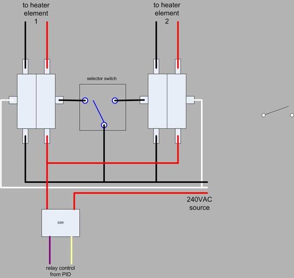
  • I'm planning on using the wiring diagram provided by P-J here.

Now the questions:
1. I'm not sure what kind of terminal blocks to get, and where to get them. I've looked on www.digikey.com and www.automation.com, among others, but there are several choices and I want to make sure I don't have to order anything more than once, or worse yet, put the wrong thing in my CP and fry something (or someone).

2. Also, the same for the breakers. What kind? Where? Safety first.

3. What kind of fuses and fuse mounts to get, and where?

4. What's the best way to cut the square holes in the enclosure panel for the PIDs? I've got a 22.5 mm knock out punch for the switches, but the square knock outs go for around $400. Is it time to invest in a Dremel? What methods have you heard/seen/done?

5. I noticed the wiring diagram doesn't have a master power switch. If I were to use one, again - how to select the right one and where to buy?

P-J, Would I wire that with L1 and L2 right after the terminal blocks?

6. Also, I'm thinking of using a 4500W element in the HLT now instead of the 5500W. Any changes to the schematic? Any parts changes besides the element of course?

Thanks again,
TB
 
Stop by your local electrical supply shop. They will be able to answer any questions you may have AND sell you what you need. As far as the your master power disconect, you could just use your CB to disco the power. If you want a main disconect on your CP, there are several to choose from, again, a good question for those supply guys.
 
Back
Top