Electric brewery plans - need help

Homebrew Talk - Beer, Wine, Mead, & Cider Brewing Discussion Forum

Help Support Homebrew Talk - Beer, Wine, Mead, & Cider Brewing Discussion Forum:

This site may earn a commission from merchant affiliate links, including eBay, Amazon, and others.

Tiber_Brew

It's about the beer.
HBT Supporter
Joined
Apr 21, 2010
Messages
2,541
Reaction score
281
Location
Upper Peninsula
Update 9.12.10: Build starts on page 20.

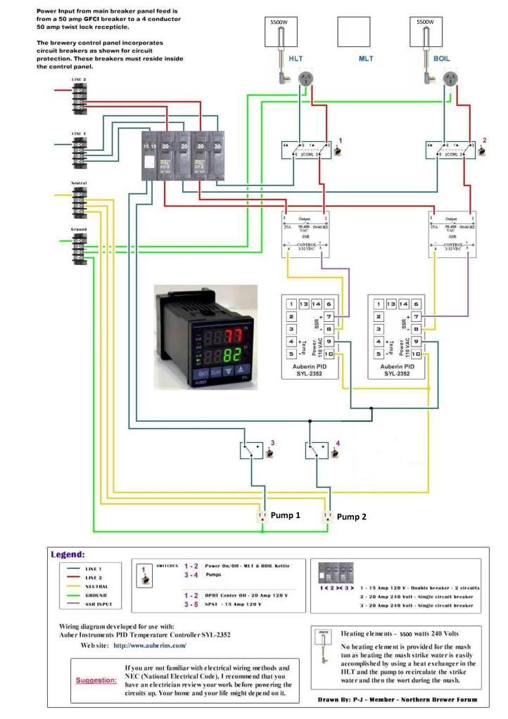
Update: Actual build is as follows: use HERMS setup in converted keg MLT and HLT. 5500W ULD element in HLT, and 4500W ULD element in BK. Will still do decoction mashing with propane burner outside. See wiring diagram below for control panel function.

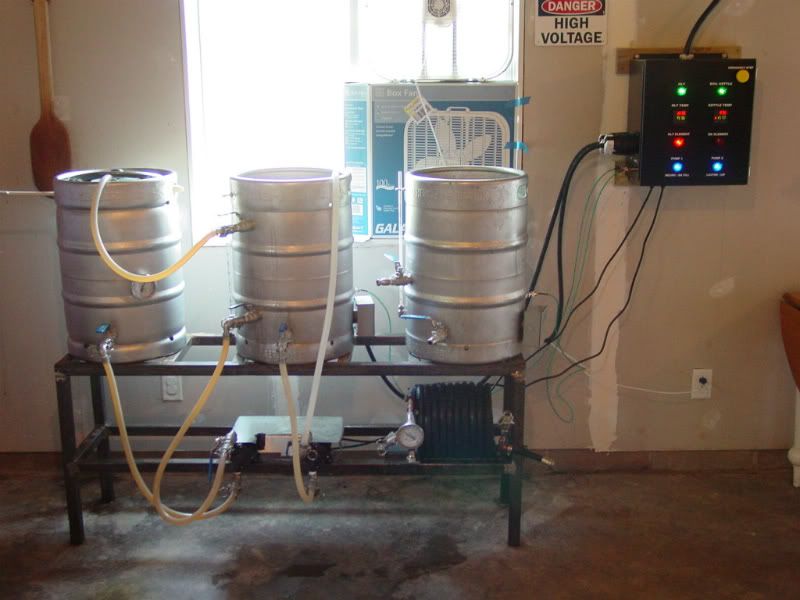
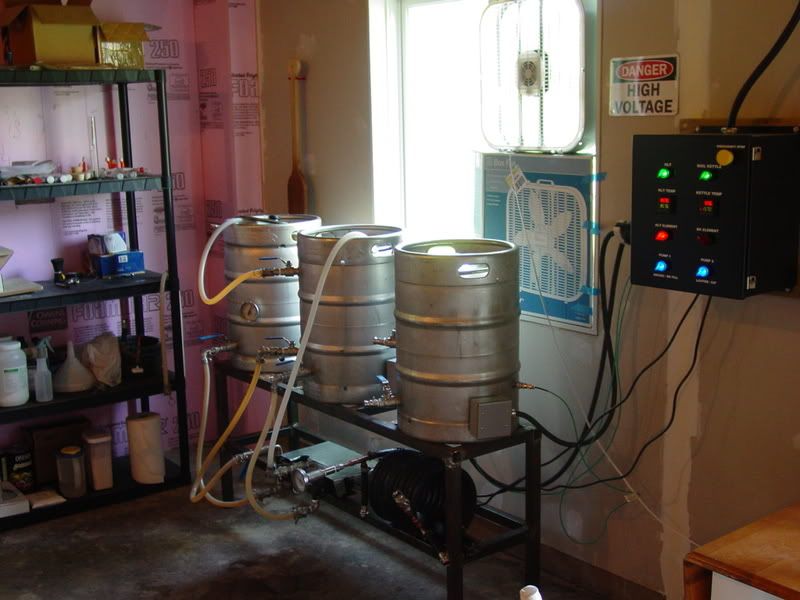
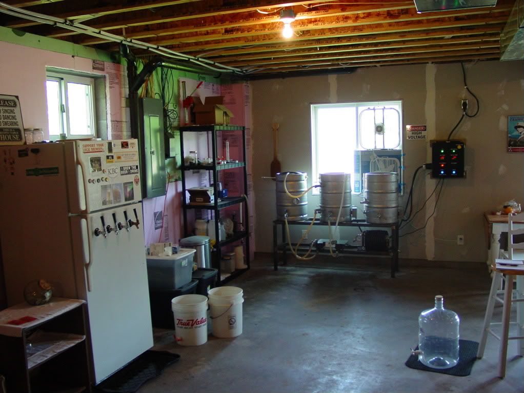
This is what the finished rig looks like:
DSC00452.jpg


DSC00453.jpg


DSC00446.jpg


DSC00447.jpg


DSC00469.jpg


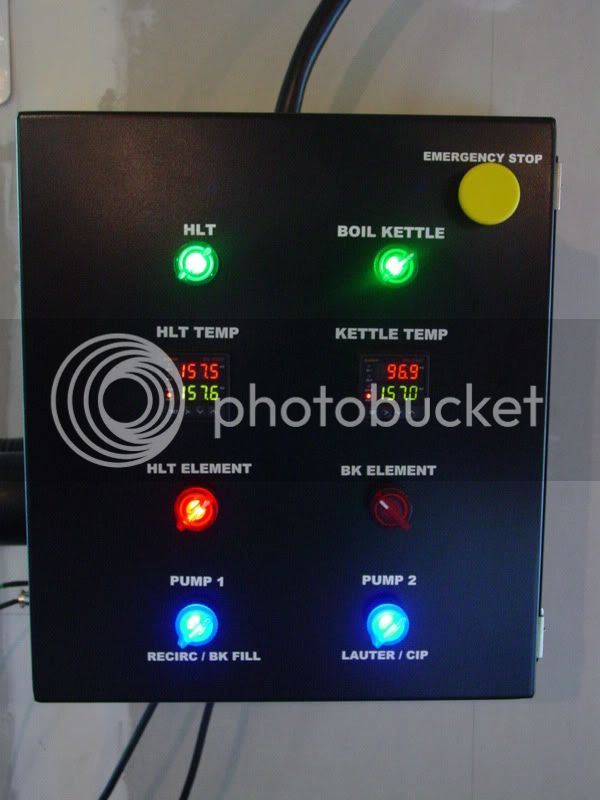
This is the final wiring diagram that represents my control panel:
Auberin-wiring1-a11-SYL-2362-4500w.jpg


-------------------------
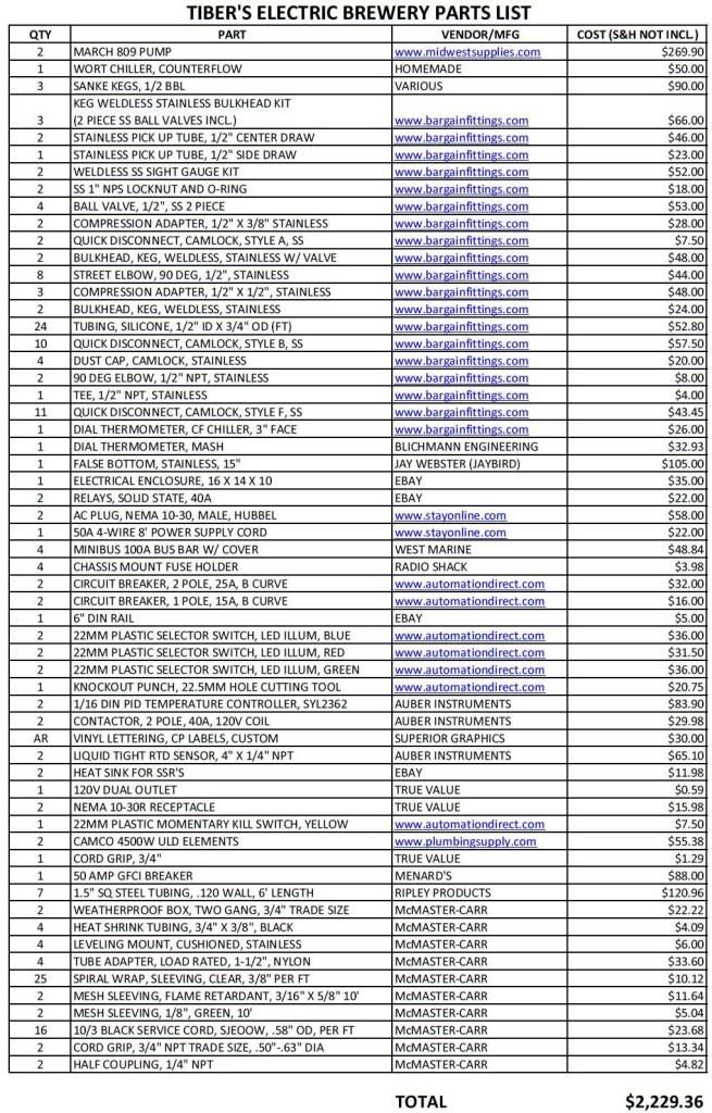
Update 1.12.2011: Parts list added.

I got a quote for powder coating the stand for $40 (not included in the parts list).

PARTSLIST1-20-11.jpg


Original post as follows:


I'm planning an electric brewery build, and with many searches, I found a plethora of great information on this site. I am just having some trouble piecing it all together for my application. I'm hoping I could get some direction from those of you who have done this before and/or have the knowledge.

Here's the setup I'm planning:

5-10 gallon batches single tier setup. Igloo cooler mash tun for single infusion and decoction mashing, with eKeggle for HLT (5500W ULD element) and eKeggle for BK (5500W ULD element). It will have two pumps (March 809) and combination hard and soft plumbed on a (hopefully) steel stand. Vorlauf and continuous sparging will be done via pumps, the BK is fed from the MLT via the pumps as well. I'm thinking of keeping the BK to counterflow chiller (link to build with pics) fed via gravity, but I'm open to thoughts on that.

As for the control panel, I want to have a master power on/off switch (emergency pwr), control the temperature of the HLT and BK with PIDs & SSRs, have on/off switches for each of the 5500W elements, and on/off switches for each of the two pumps. I've been told it's a good idea to have an SSR for each leg of the elements, so I would end up with 4 SSRs total. Thoughts on that? I'm thinking of getting this PID from Auber Instruments since I think it will do the job well enough for me. The SSR I've got my eyes on here. For the elements, I'd like to have illuminated push button switches so I visually know when the elements have power available to them. I'd really like to have a button for on, and a separate button for off, but push on/push off buttons are acceptable. For the pumps, I was thinking illuminated selector switches. I've looked at automationdirect.com and found some promising parts (although some are out of stock).

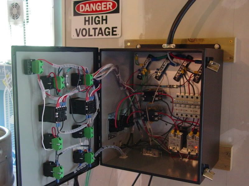
Since the elements will run on 240VAC, and the pumps and PIDs run on 120VAC (not sure what the illuminated switches run on - right from the 120V?), I'm not sure how to distribute and properly ground the power in the control panel. I'm also not sure about how to transmit the power to the kettles, hardware wise. Should the wires going to the kettles plug into the control panel? Or should they be wired more permanently? And how? Are fuses and/or breakers necessary/recommended? Where? How?

I'm anxious to get started, but smart enough to know not to rush into it. I'm looking forward to your help! I will provide pictures as this progresses.

Thanks!

Tiber_Brew
 
Last edited:
I found this wiring diagram, and it appears to be fairly close to my application. I was thinking it might be a good place to start as far as wiring. I still have so many questions!

Auberin-wiring1-a6.jpg


Cheers!
TB
 
This is REALLY close to what I am planning...I think I just found my wiring diagram, thanks. I can't answer your questions but I will certainly be lurking gathering up all the knowledge I can. Thanks for posting this.
 
No problem, Mose. I've been in the same boat here; I need something, search for it, find someone asking something pretty close, and watch that thread for a while. Most of the time I'll end up finding what I need and never have to start a new thread.

That diagram doesn't fit my design quite exactly, but, damn, it is it ever close.

TiberwillhappilypayitforwardBrew
 
What are your questions?
That diagram looks like a great place to start.

I would note that S1 and S2 are going to have to be VERY heavy duty to sink 20 amps of current to the elements.
 
wanna know my thoughts? yes? ok...

for the illuminated switches, must are NOT 120V, especially if they're LED. check the datasheet. read this thread for ideas on how to get the voltages right and not blow anything up.

now, looking at the drawing, that is set up to get 2 seperate 240V lines fed to the control box, so you can run both elements at teh same time, but notice the breakers are 20 amps. you need 30 amps for your 5500W elements. do you actually have 2 separate lines available? I know most people are just plugging into a dryer outlet, cause thats whats available, but it will only let you run one element at time. I wouldn't say thats a problem, because once you start your sparge, your water should be up to temp and you can fire up your BK. that just means you should have some kind of selection switch for which element is active. easiest way in my book is to have a DPST switch cut the yellow and purple lines between the PIDs and SSR.

I have more thoughts too, but I want to know what your power source is going to be. 3 prong dryer outlet, 4 prong dryer outlet, straight to your electric panel?
 
This diagram is a good starting point. I would echo the 30 A circuit breaker suggestion, and if you don't use a gfci in the spa box, then go with 30 A gfci circ brkrs. Also I would suggest 40 amp SSRs instead of 25 A as the diagram suggests, since your 4500 W elements will draw 19 to 20.5 amps at 240 v 0r 220 v depending on your house voltage. This is pretty close to their max, and they will get hot. In either case, you will need good heat sinks for the SSRs.

Another option for SSRs is what is called an SSC, solid state contactor. They are SSRs with built in heat sinks, and are designed for heavy loads. I got mine off eBay. They were made by Crydom as I recall.

Also for my eHLT I am using a two pole relay since it won't switch on and off as often as the eBK SSR will. The advantage here is both legs are controlled separately by the 2 pole relay, and the failure mode for relays is in the open mode, while SSRs or SSCs can fail in the closed mode.

Also, I like the 2 pole switch between the SSR and the element, allowing you to positively turn off the power to the element, and knowing that both legs of the 240 V are off.

Finally, on my panel I have a master switch that controls all the 120 volt devices, and when this is turned off, nothing can turn on. Another finally, is you should consider fuses on the hot line feeding each of your 120 v devices, they are cheaper than replacing a component that you have let the smoke out of.
 
His elements are 5500W, not 4500W. The diagram is not his system, just a diagram for a system that is very close to what he wants.

I would still go with 40A SSR's, even if you only need 25A. The price difference is basically nothing. You can find 40A SSR's with heatsinks on ebay for $14 (free shipping).

About the switches. 120V illuminated switches are not hard to find. I shopped for most of my small electronics as mouser.com and found illuminated switches that run off 120VAC. They were about $1 per switch.
 
What are your questions?
That diagram looks like a great place to start.

I would note that S1 and S2 are going to have to be VERY heavy duty to sink 20 amps of current to the elements.

Indeed, I did start with that diagram, but modified it quite a bit, including relocating the S1 and S2. No longer require the heavy duty switches.

See below
 
I would strongly suggest you add S1 and S2 back for safety reasons. You can get double pole 250 v 30 A switches off eBay for 4 or 5 bucks right now. Do an eBay search for NKK switches. I got a pair of these for my element shutoffs and like the ability to positively switch off the power in both legs of the element.
 
wanna know my thoughts? yes? ok...

for the illuminated switches, must are NOT 120V, especially if they're LED. check the datasheet. read this thread for ideas on how to get the voltages right and not blow anything up.

I've been looking at illuminated switches where the indicator takes full voltage, so no worry there. Thanks for the concern though! I'm glad there are many good thinkers on HBT who pay attention to those details!

now, looking at the drawing, that is set up to get 2 seperate 240V lines fed to the control box, so you can run both elements at teh same time,
Not quite. It's a 240VAC input, which is basically two 120VAC legs, a neutral, and a ground. Some bus bars or terminal blocks will distribute the power from there, so long as I don't run too many circuits in parallel and trip the breakers.

but notice the breakers are 20 amps. you need 30 amps for your 5500W elements.
By my calculations: 5500/2= 2750W
2750W/120V=22.9Amps

Perhaps I do need 30 amp breakers?


This is a great thinking.There are different types of switching circuit in market.The conventional idea can be thermistor.or different kind of IC controlled logic circuit can be implemented.Because uyou are having a huge load so You have to keep this away from your house firepits and other risky elements.
I'm sorry...what?

This diagram is a good starting point. I would echo the 30 A circuit breaker suggestion, and if you don't use a gfci in the spa box, then go with 30 A gfci circ brkrs. Also I would suggest 40 amp SSRs instead of 25 A as the diagram suggests, since your 4500 W elements will draw 19 to 20.5 amps at 240 v 0r 220 v depending on your house voltage. This is pretty close to their max, and they will get hot. In either case, you will need good heat sinks for the SSRs.
Perhaps the 30A breakers are better. I'm actually using 5500W elements instead of the 4500W from the diagram, so the higher current handling breakers are even more deserving, eh?

Finally, on my panel I have a master switch that controls all the 120 volt devices, and when this is turned off, nothing can turn on. Another finally, is you should consider fuses on the hot line feeding each of your 120 v devices, they are cheaper than replacing a component that you have let the smoke out of.
Are you suggesting replace the breakers with fuses? Or add fuses in addition to the breakers?

His elements are 5500W, not 4500W. The diagram is not his system, just a diagram for a system that is very close to what he wants.
Right-o

I would still go with 40A SSR's, even if you only need 25A. The price difference is basically nothing. You can find 40A SSR's with heatsinks on ebay for $14 (free shipping).

About the switches. 120V illuminated switches are not hard to find. I shopped for most of my small electronics as mouser.com and found illuminated switches that run off 120VAC. They were about $1 per switch.
Found very similar switches. Thanks Walker.


OK, so here's a bit of an update:

I'm using two double pole SSRs, and moving the element power switches from after the SSRs to before the SSRs (between PID and SSR). I'm switching both legs of the elements with the DPSSR instead of one leg with standard SSRs, and I can turn both legs completely off with one illuminated switch that sees about 12VDC. I also am going to use heat sinks for both the DPSSRs, since they're 25amps. If I have problems with those, I'll get the 40amp double pole SSRs. (The 25A double pole SSRs were free, BTW.)

I also think I'm going with the Auber PID SYL-2352 instead of the universal. Perhaps the universal will still work for the BK, since I don't need real precise algorithms to boil sugar water.

Here is a revised, but not entirely up to date diagram I modified today
WiringDiagram5500.jpg


Keep in mind I'm moving the switches 1&2 behind the SSRs so I can use low voltage illuminated ones and both legs will be shut off due to the double pole SSRs.

EDIT: switches 1 & 2 are going to be SPST on the positive lead to the SSR since it's DC. (On both SSRs) Thought I'd clear that up too.

I might also use bus bars instead of terminal blocks, but that's minor.


I appreciate all the feedback and questions! Keep 'em coming! Any feedback is welcome!
 
I bought 25A breakers for my ststem, and then started worrying about my 5500W element causing nuisance trips of the breaker because I didn't give them enough margin. Fortunately, I have not had the breakers trip at all for me, and I've brewed twice with it, am cooking babyback ribs in it now (check out "sous vide" cooking style) and have played with the thing a BUNCH making sure it all worked. Not one trip of a breaker.

SO... I'd go with 30A breakers, to avoid the concern of tripping when there really is no problem. Keep in mind that this might mean you'll have to use fatter wires to deal with inside the control box. (Your wire has to handle whatever current the breaker will allow through.)

About the fuses mentioned earlier....

He's not suggesting taking out your breakers and using fuses instead. He's talking about using little tiny fuses to protect things like the PID. Those things don't need much current to operate, so you can protect them with very small fuses that will blow if something goes wrong. The diagram has the 120V stuff on a 15A breaker. This is pretty much like an outlet in your house. But, 15A is WAY MORE than enough to kill a PID, so you protect it with a small (1A?) fuse so that the PID is properly protected.

I actually don't have any fuses in my system at this point, but it's something I want to add.
 
Thanks for the good info, Walker. I'm def going to look into 30A breakers now. Perhaps 1A fuses are in order too...

I'll run this info by the electrical engineers at work, and see what they think of this diagram and your suggestions. (I'm just an electronically retarded mechanical engineer.)

Cheers guys!
TibernotmuchlongernowBrew
 
...
That diagram doesn't fit my design quite exactly, but, damn, it is it ever close.

TiberwillhappilypayitforwardBrew
Just saw this post (have not read the balance of the thread yet).

What do you need that is different. The diagram you posted was planned and drawn by me. I'd be more than willing to make any changes that you need for your setup.

Let me know.

(Back to reading the thread.)
 
Ok.. Just finished reading the thread.
Tiber_Brew - we really need to talk. I want you to have it right and safe. There is a bit of mis-information posted in this thread.

Please tell me what your overall objective and design plan calls for. I can help.
 
Your drawing is spot on.
I would leave the DPST switches between the SSR's and the elements. It's safer that way, and if the SSRs fail closed, you can still kill the power to the elements.
A couple other things I'd change (Or at least recommend)
Lose the home type of breakers. They have to be installed in a special panel, and are not really available in smaller amperages.

Install a DIN rail in your enclosure, and use DIN mount breakers like these:
The wiring doesn't change, but it'll be safer just because they mount securely, and the connections are behind plastic to keep your fingers out.

They will also enable you to put the appropriate breakers on your pumps. 15 amps is way too much for a 1.4 amp motor. Use 2 amp "D curve" single pole DIN breakers.
(Think of "B Curve" as fast blow for resistive loads like elements, and "D Curve" as slow blow for inductive loads like motors)

The other thing I'd do is install an SSR on both legs of the elements (So a total of 4 SSRs). It's personal preference for me, and many here have used just one. But if you manage to touch the wire after a single SSR, even if it's off, you risk completing the circuit to the un-switched side. Ouch.

Oh, And use terminal strips. Buss bars are not insulated in any way. They can short to you, or they can short to the enclosure. Neither is a good place to be. At least terminal strips are insulated from whatever you are mounting them to.
 
Not quite. It's a 240VAC input, which is basically two 120VAC legs, a neutral, and a ground. Some bus bars or terminal blocks will distribute the power from there, so long as I don't run too many circuits in parallel and trip the breakers.
embarrassed i missed that one, but you're definitely right. looking good to me. I second the additional SSRs so you can switch both legs of th 240, and really think a selector switch between the pid and SSR is good choice, just so you never accidentally fire both up at the same time and pop your breakers.
 
Ok.. Just finished reading the thread.
Tiber_Brew - we really need to talk. I want you to have it right and safe. There is a bit of mis-information posted in this thread.

Please tell me what your overall objective and design plan calls for. I can help.

Please publicly point out whatever misinformation is in here for the betterment of the community and to correct anyone who might be doing something unsafe in their own system.
 
By my calculations: 5500/2= 2750W
2750W/120V=22.9Amps

I just noticed this. I don't where you were going with the "5500/2=2750W" and then "2750W/120V" calculations above.

To figure amp draw, you just divide the power by the voltage.

5500W/240V = 22.9A

You accidentally arrived at the right answer because you first divided by 2 and then divided 120V, which is mathematically the same as dividing by 240V, but something is wrong with the thought process you were using there.
 
I'm using two double pole SSRs, and moving the element power switches from after the SSRs to before the SSRs (between PID and SSR). I'm switching both legs of the elements with the DPSSR instead of one leg with standard SSRs, and I can turn both legs completely off with one illuminated switch that sees about 12VDC.

EDIT: switches 1 & 2 are going to be SPST on the positive lead to the SSR since it's DC. (On both SSRs) Thought I'd clear that up too.

From what I have read, SSR's can fail in the "ON" mode. If that happens, then the switches you put in to kill the SSR control signal from the PID won't accomplish anything and the lines going to the heater element will be live.

You are better off actually killing the 240V hot lines rather than the SSR control signal from the PID.

And... if you are really wanting to keep it as safe as possible, I personally wouldn't use a big DPST toggle switch to directly control the 240V lines. There will be a lot of current flowing through those switches . I thought about using big burly toggle switches like that in my system but then realized that there would be 23A flowing through that switch and I would be directly touching it... possibly with wet hands.

not only that, but my switches are on a hinged door. If I would have used big toggle switches capable of handling the 240V/23A, I would have had to run very heavy gauge wiring to that switch on the panel. Opening and closing the door would have been more difficult.

So... I opted to use a 2-pole contactor to pass the 240V through to the elements, and that thing (along with the large wires) is down in the belly of my control box. The contactor is triggered with a 120V signal (and draws only 0.5A). So, I have a 120V illuminated switch on the door with a small wire that feeds down into the contactor to enable it.

The contactors take up a lot of space, but I really didn't want to touch a big 240V/23A toggle switch. (The contactor was the same price as the Big Switch, too.)
 
Please publicly point out whatever misinformation is in here for the betterment of the community and to correct anyone who might be doing something unsafe in their own system.
Fair enough.

...
now, looking at the drawing, that is set up to get 2 seperate 240V lines fed to the control box, so you can run both elements at teh same time, but notice the breakers are 20 amps. you need 30 amps for your 5500W elements. do you actually have 2 separate lines available?
...
Only one line is run from the main panel. 240V 4 wire (120V A phase, 120V B phase, Neutral and Ground) The line and outlet must be rated for the ampericity of the breaker in the main panel. The diagram first shown is for 2 - 4500W elements using a 50 amp GFCI breaker in the main panel. This in not suitable for 5500W elements.

...
since your 4500 W elements will draw 19 to 20.5 amps at 240 v 0r 220 v depending on your house voltage.
...
A 4500W 240V element will draw 18.75 amps at 240V. The resistance of the element does not change so - at 220 volts it will only provide 4125 watts of power or draw about 17.19 amps.

... you should consider fuses on the hot line feeding each of your 120 v devices, they are cheaper than replacing a component that you have let the smoke out of.
Thank you for that. The latest diagram shows fuses (1A) in the PID power lines.

Indeed, I did start with that diagram, but modified it quite a bit, including relocating the S1 and S2. No longer require the heavy duty switches.
This is not a good idea. You really need to have switches to kill power to the elements. This is a serious safety issue.

...
Lose the home type of breakers. They have to be installed in a special panel, and are not really available in smaller amperages.

Install a DIN rail in your enclosure, and use DIN mount breakers like these:
The wiring doesn't change, but it'll be safer just because they mount securely, and the connections are behind plastic to keep your fingers out.
...
Excellent suggestion. I show standard breakers for illustration purposes. (I snatch images from the web to illustrate the concept)

Ok.. That's some of it (BTW most have been corrected and/or mentioned in the thread)

A new drawing that might help:


(Click the image for a larger picture)

Switches 1 & 2 are rated for 30A 240V. I chose these particular switches (DPDT - Center Off) as they cost about the same as one rated the same in different versions. This way the same switch can be used in various configurations. It is relative small as well.

hicap.jpg


I hope this all helps and any changes that the OP would like to see, I'll try to accomodate.
 
Just a thought...

When selecting parts for my system, I came across panel-mount circuit breakers that had nice illuminated rocker switches on them for ON/OFF. If you used those, that would combine the breaker and element kill switches into a single component.

I think I saw the panel mount rocker activated breakers at mouser.com.
 
Wow, lots of good stuff posted here since I've last been on! I'll try to address some of the things best I can.

Let's see here...

What do you need that is different. The diagram you posted was planned and drawn by me. I'd be more than willing to make any changes that you need for your setup.

Ok.. Just finished reading the thread.
Tiber_Brew - we really need to talk. I want you to have it right and safe. There is a bit of mis-information posted in this thread.

Please tell me what your overall objective and design plan calls for. I can help.

Thanks for offering your help! Basically, what I want to do is heat the HLT and BK with 5500W elements. I want to control them with PIDs and double pole SSRs (kind of like using two SSRs per element). I want to be able to manually power off the elements with the PIDs still on. I also need to switch on/off two March 809 pumps on 120VAC. I'd like to use illuminated switches if possible for everything so I can get a visual clue from a distance if needed. The mashing will be done single infusion in a 10gal round cooler.

A couple other things I'd change (Or at least recommend)
Lose the home type of breakers. They have to be installed in a special panel, and are not really available in smaller amperages.

Install a DIN rail in your enclosure, and use DIN mount breakers like these:
The wiring doesn't change, but it'll be safer just because they mount securely, and the connections are behind plastic to keep your fingers out.

They will also enable you to put the appropriate breakers on your pumps. 15 amps is way too much for a 1.4 amp motor. Use 2 amp "D curve" single pole DIN breakers.
(Think of "B Curve" as fast blow for resistive loads like elements, and "D Curve" as slow blow for inductive loads like motors)
I was looking at panel mount breakers that screw into the front or side panel of my enclosure, but yours is a good idea too. I'll have to look into that. What's involved in putting in a DIN rail? Where do you get them? Thanks!

The other thing I'd do is install an SSR on both legs of the elements (So a total of 4 SSRs). It's personal preference for me, and many here have used just one. But if you manage to touch the wire after a single SSR, even if it's off, you risk completing the circuit to the un-switched side. Ouch.
See above. I'm using double pole SSRs, so that's essentially like using two SSRs per element like you're suggesting. Both legs will be switched by one SSR, for both the BK and HLT. I agree that it's a good idea to not have a hot leg left closed to the element(s).

Oh, And use terminal strips. Buss bars are not insulated in any way. They can short to you, or they can short to the enclosure. Neither is a good place to be. At least terminal strips are insulated from whatever you are mounting them to.
I've seen some bus bars that are insulated from the chassis (enclosure in my case). Would you still not recommend that? Why? Thanks.

I'll try to address more soon.

TB
 
I just noticed this. I don't where you were going with the "5500/2=2750W" and then "2750W/120V" calculations above.

To figure amp draw, you just divide the power by the voltage.

5500W/240V = 22.9A

You accidentally arrived at the right answer because you first divided by 2 and then divided 120V, which is mathematically the same as dividing by 240V, but something is wrong with the thought process you were using there.
Here's my thinking:

Each leg is 120VAC, and each has its own breaker. And the element draws its 5500W from the sum of the two legs. So, one leg @ 120VAC supplies half the power to the element. (5500/2)/120=22.9 amps. I'm addressing each breaker, not the total system.

From what I have read, SSR's can fail in the "ON" mode. If that happens, then the switches you put in to kill the SSR control signal from the PID won't accomplish anything and the lines going to the heater element will be live.

You are better off actually killing the 240V hot lines rather than the SSR control signal from the PID.

And... if you are really wanting to keep it as safe as possible, I personally wouldn't use a big DPST toggle switch to directly control the 240V lines. There will be a lot of current flowing through those switches . I thought about using big burly toggle switches like that in my system but then realized that there would be 23A flowing through that switch and I would be directly touching it... possibly with wet hands.

not only that, but my switches are on a hinged door. If I would have used big toggle switches capable of handling the 240V/23A, I would have had to run very heavy gauge wiring to that switch on the panel. Opening and closing the door would have been more difficult.

So... I opted to use a 2-pole contactor to pass the 240V through to the elements, and that thing (along with the large wires) is down in the belly of my control box. The contactor is triggered with a 120V signal (and draws only 0.5A). So, I have a 120V illuminated switch on the door with a small wire that feeds down into the contactor to enable it.
Can you tell me more about the contactors? How are they wired? How is the toggle wired? What voltage and current ratings are required for each? I like that thinking...the more separation between me and a deadly stream of electrons the better.

The contactors take up a lot of space, but I really didn't want to touch a big 240V/23A toggle switch. (The contactor was the same price as the Big Switch, too.)
You've got my attention now!

TiberthegreatfulBrew
 
Here's my thinking:

Each leg is 120VAC, and each has its own breaker. And the element draws its 5500W from the sum of the two legs. So, one leg @ 120VAC supplies half the power to the element. (5500/2)/120=22.9 amps. I'm addressing each breaker, not the total system.
That's not how AC current works. BOTH legs will see the full load. If a 220v device pulls 20 amps, both legs will pull 20 amps.
BOTH legs of a 220v device are 220 volts! 220v AC is about the potential between conductors. You must understand this. There is no 110 volt wire in your 3 wire 220v element.
220v single phase has 4 conductors. 2 Hots, a neutral, and a ground.
Your element is wired to H1, H2 and ground. The potential between H1 and H2 is always 220v!
Nothing should ever be attached to ground, except for the ground for a device (The flange in your elements, in this case)
H1 and H2 = 220v
H1 and Neutral = 110v
H2 and Neutral = 110v
H1 or H2 to ground = big sparks at best - I don't have to tell you about worse...


Can you tell me more about the contactors? How are they wired? How is the toggle wired? What voltage and current ratings are required for each? I like that thinking...the more separation between me and a deadly stream of electrons the better.
Contactors are just really big relays. You use some low current signal to "pull" the contactor closed to connect a high current load.
In my rig, I'll be using 25 amp contactors to connect the 220v feed, to the input of the SSRs. This way, if the contactor isn't closed, there isn't any voltage, even to the SSRs.

I was looking at panel mount breakers that screw into the front or side panel of my enclosure, but yours is a good idea too. I'll have to look into that. What's involved in putting in a DIN rail? Where do you get them? Thanks!
DIN rail just bolts to your enclosure, and rail mount devices (Like the breakers, contactors, SSRs, and any other thing you can think of) just snap on and "grab" the DIN rail.

I've seen some bus bars that are insulated from the chassis (enclosure in my case). Would you still not recommend that? Why? Thanks.
I guess I've never seen them like that. When you say buss bar, I think grounding buss in a breaker panel. Strip of metal with holes and screws.
I'd use terminal strips like these, or these. (Appropriately sized for your current load, of course)
But, if you decide to install DIN rail and go that route, then you can use these! :mug:
They pretty much rawk. There's a reason these are what you find in every industrial automation cabinet. They are pretty much the standard when it comes to building things like this on a factory floor.


I recommend lots and lots of research, my friend. 220v @ 50a is enough to send you across the room if you get 1 wire wrong. Not trying to scare you away! This is the DIY forum after all. Lots of us here have done what you are doing. Several of the guys that have replied to your thread here are enjoying a beer brewed on their electric rig. But you gotta know, when you grab onto a wire, exactly what to expect when that wire touches another, or it will bite you in the ass. (Trust me ;) )

In the end, I'm just another hack on an anonymous beer forum, and I'm not an electrician - So take my advice for what you paid for it :D
 
Your thinking is not quite right on the amps with 240V. Current will flow from the 120V line that is high all the way down to the 120V line that is low. Yesn it's two poles in the breaker, but the current all flows through both of them.

As for two 5500W elements... 5500W is overkill for a HLT. You CAN use it, but if plan to run both 5500W elements at the same time, you're going to be sucking in 46A. You will probably have issues supplying all of that with a 50A circuit.

If you only want to run one element at a time, you'll be fine. But... 5500W for the HLT isn't really necessary.
 
Your thinking is not quite right on the amps with 240V. Current will flow from the 120V line that is high all the way down to the 120V line that is low. Yesn it's two poles in the breaker, but the current all flows through both of them.

Oooo! (Think "Hercules! Hercules! clap)
Lets talk about phase! :D

Walker's right
 
Tiber_Brew,

I spent a little time tonight and reworked the drawing to reflect some of the things that you are dealing with. It now shows the PIDs that you are using:


(Click on the image to see a full scale picture)

Please let me know of any other changes that you would like to see.

EDIT: By the way - the large image is setup and formatted to print on a 11" X 17" sheet.
 
Thanks for putting all this information out there, I've been studying other threads, Walker, Sweetsounds and a few others, but it's all starting to come together for me in this one. This diagram is dead on what I need minus the HLT since I'm going two vessel.

I have officially wasted a lot of time at work and home reading and re-reading this information, and will likely waste much more. If only my ingredients arrived today I wouldn't have to read about beer all weekend and I could have brewed some.
 
That's not how AC current works. BOTH legs will see the full load. If a 220v device pulls 20 amps, both legs will pull 20 amps.
BOTH legs of a 220v device are 220 volts! 220v AC is about the potential between conductors. You must understand this. There is no 110 volt wire in your 3 wire 220v element.
220v single phase has 4 conductors. 2 Hots, a neutral, and a ground.
Your element is wired to H1, H2 and ground. The potential between H1 and H2 is always 220v!
Nothing should ever be attached to ground, except for the ground for a device (The flange in your elements, in this case)
H1 and H2 = 220v
H1 and Neutral = 110v
H2 and Neutral = 110v
H1 or H2 to ground = big sparks at best - I don't have to tell you about worse...
Makes total sense, even to this poor mechanical engineer who slept through circuits and electrical power & machinery courses. Thanks for pointing that out.

Contactors are just really big relays. You use some low current signal to "pull" the contactor closed to connect a high current load.
In my rig, I'll be using 25 amp contactors to connect the 220v feed, to the input of the SSRs. This way, if the contactor isn't closed, there isn't any voltage, even to the SSRs.
I understand how they work. How do you wire one? Specifically in my case? I'm interested in using those, since that adds extra safety factor magnitude. Safe is good.


DIN rail just bolts to your enclosure, and rail mount devices (Like the breakers, contactors, SSRs, and any other thing you can think of) just snap on and "grab" the DIN rail.
Intrigued. Might look into this as well. Thanks!


I guess I've never seen them like that. When you say buss bar, I think grounding buss in a breaker panel. Strip of metal with holes and screws.
I'd use terminal strips like these, or these. (Appropriately sized for your current load, of course)
But, if you decide to install DIN rail and go that route, then you can use these! :mug:
They pretty much rawk. There's a reason these are what you find in every industrial automation cabinet. They are pretty much the standard when it comes to building things like this on a factory floor.
Sweeeeet. [rubs his hands together]


I recommend lots and lots of research, my friend. 220v @ 50a is enough to send you across the room if you get 1 wire wrong. Not trying to scare you away! This is the DIY forum after all. Lots of us here have done what you are doing. Several of the guys that have replied to your thread here are enjoying a beer brewed on their electric rig. But you gotta know, when you grab onto a wire, exactly what to expect when that wire touches another, or it will bite you in the ass. (Trust me ;) )
I've spent about 20 hours this week alone researching this stuff. That doesn't include the time I spent picking the brains of the electrical engineers at work. I'm learning more and more, and becoming more and more interested in this. I'm also getting more excited. I appreciate all the help I'm getting here at HBT!

In the end, I'm just another hack on an anonymous beer forum, and I'm not an electrician - So take my advice for what you paid for it :D
Haha, you sound alright in my book :mug:
 
As for two 5500W elements... 5500W is overkill for a HLT. You CAN use it, but if plan to run both 5500W elements at the same time, you're going to be sucking in 46A. You will probably have issues supplying all of that with a 50A circuit.

If you only want to run one element at a time, you'll be fine. But... 5500W for the HLT isn't really necessary.

What would you recommend for the HLT? 4500? 4000? Would ULD still be a good idea for HLT? I was thinking I would use ULD for both BK and HLT for a bit of protection against dry fire damage.
 
Tiber_Brew,

I spent a little time tonight and reworked the drawing to reflect some of the things that you are dealing with. It now shows the PIDs that you are using:


(Click on the image to see a full scale picture)

Please let me know of any other changes that you would like to see.

EDIT: By the way - the large image is setup and formatted to print on a 11" X 17" sheet.

Thanks for redrawing that PJ. There are just a few things to point out that are different from what I now have in mind.

1. The SSRs I'm using are double pole. Both legs of the element will be switched by one SSR. This is true for both the BK and the HLT.

2. I don't, as of yet, plan on having separate switches for the PID power. I'm just letting those power up when I plug the CP in. Unless, of course, there's a reason you would recommend such a thing. I'm sure it's cheap to wire in just a couple more toggles.

3. Can you show how I would wire in contactors for the elements as Walker and SweetSounds mentioned? I'm very interested in doing that.

Thanks for being a big help PJ. You're pretty good with those diagrams. I tried mocking some ideas up on MS Visio, but gave up after a while. I like yours better. (I can design aerospace avionics that won't overheat in flight, but drawing electrical schematics - no thanks.)
 
Sorry for crowding the thread....but one more tangential question:

What are your guys' thoughts on using the universal PID or fuzzy logic PID from Auber Instruments? It seems to be only about $4 difference. I'm only using the PIDs to reach and maintain strike water and lauter water temps, and for ramping up a boil and maintaining a boil.

I went ahead and assumed that the universal PIDs were sufficient for both the BK and HLT. Thoughts?

universal PID (Auber)

fuzzy logic PID (Auber)

TiberPIDlogicisn'ttheonlythingfuzzynowBrew
 
Thanks for putting all this information out there, I've been studying other threads, Walker, Sweetsounds and a few others, but it's all starting to come together for me in this one. This diagram is dead on what I need minus the HLT since I'm going two vessel.

I have officially wasted a lot of time at work and home reading and re-reading this information, and will likely waste much more. If only my ingredients arrived today I wouldn't have to read about beer all weekend and I could have brewed some.

You're lucky your employer doesn't block this awesome site. My Big Brothers in board rooms don't think it's moral for me to surf "alcohol" sites at work. Can't say I have a legitimate argument, but I'd really like to poke in during a break at work here and there.

TB
 
Thanks for redrawing that PJ. There are just a few things to point out that are different from what I now have in mind.

1. The SSRs I'm using are double pole. Both legs of the element will be switched by one SSR. This is true for both the BK and the HLT.

2. I don't, as of yet, plan on having separate switches for the PID power. I'm just letting those power up when I plug the CP in. Unless, of course, there's a reason you would recommend such a thing. I'm sure it's cheap to wire in just a couple more toggles.

3. Can you show how I would wire in contactors for the elements as Walker and SweetSounds mentioned? I'm very interested in doing that.

Thanks for being a big help PJ. You're pretty good with those diagrams. I tried mocking some ideas up on MS Visio, but gave up after a while. I like yours better. (I can design aerospace avionics that won't overheat in flight, but drawing electrical schematics - no thanks.)

Give me a day and I'll do my best to put it together for you.

Re: PID power. I think it's a good idea to be able to power them down without pulling the plug. Think about it.

Question - Do you have a web link for the specific SSR that you want to use? I'd like to see the item and its connection layout.

How about the contactors? Need to know the rating on the ones you intend to use. (Coil voltage? Size? et.al.)

You got the plan, let me draw it out. (I'll also judge for safety. I have a strong background in electrical work. Originally went through trade school in 1957. AND that was only the beginning.! You betcha.. I'm older than rocks. :rolleyes: )

Keep me posted and lets get er done.
 
You're lucky your employer doesn't block this awesome site. My Big Brothers in board rooms don't think it's moral for me to surf "alcohol" sites at work. Can't say I have a legitimate argument, but I'd really like to poke in during a break at work here and there.

TB

:D
I'm the guy that runs the firewalls and perimeter networks... If they try to block it on me, I'll just add a policy that says my PC can still get access to HBT! I love my job...

:ban:
 
Give me a day and I'll do my best to put it together for you.
I appreciate it, PJ!

Re: PID power. I think it's a good idea to be able to power them down without pulling the plug. Think about it.
Is that to protect it from power surges at plug in?

Question - Do you have a web link for the specific SSR that you want to use? I'd like to see the item and its connection layout.
Sure do. Here are the SSRs from Tyco. You can get the datasheet from that site too.

How about the contactors? Need to know the rating on the ones you intend to use. (Coil voltage? Size? et.al.)
Um...Walker? SweetSounds? I'm sort of at a loss here. I wish I knew what to tell you here, PJ. Perhaps our friends will chime in soon to fill in the blanks.

You got the plan, let me draw it out. (I'll also judge for safety. I have a strong background in electrical work. Originally went through trade school in 1957. AND that was only the beginning.! You betcha.. I'm older than rocks. :rolleyes: )

Keep me posted and lets get er done.
Hey, sounds great! Wish I could return the favor. Let me know if you need to interpret a GD&T engineering drawing or improve thermal management in aerospace avionics! (Or if you're in Michigan's UP and want a beer!)

TB
 
:D
I'm the guy that runs the firewalls and perimeter networks... If they try to block it on me, I'll just add a policy that says my PC can still get access to HBT! I love my job...

:ban:

We are to small to have an official IT guy and bother with blocking sites. Good news is even the Military hasn't blocked it yet, so I've been told.
 
Back
Top