- Joined
- Nov 6, 2007
- Messages
- 62,016
- Reaction score
- 6,923
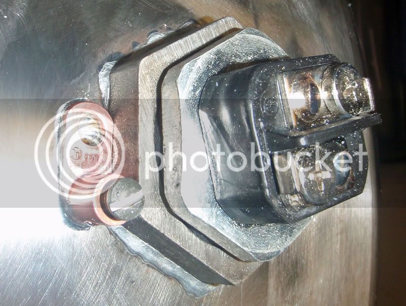
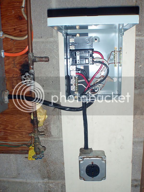
I believe this is common. That section isn't plated.


![Craft A Brew - Safale S-04 Dry Yeast - Fermentis - English Ale Dry Yeast - For English and American Ales and Hard Apple Ciders - Ingredients for Home Brewing - Beer Making Supplies - [1 Pack]](https://m.media-amazon.com/images/I/41fVGNh6JfL._SL500_.jpg)
Scut: yes very similar. I took a 1/2" brass long nipple and ground the end to a taper on a belt grinder and used that as the form to pull through.
Also: I just edited my original post with a parts list. Enjoy!
-Joe
I will be recirculating with an IC. But if I move to a plate chiller eventually, then the thermowell would be useless regardless of where in the BK it is, right?
-Joe
")
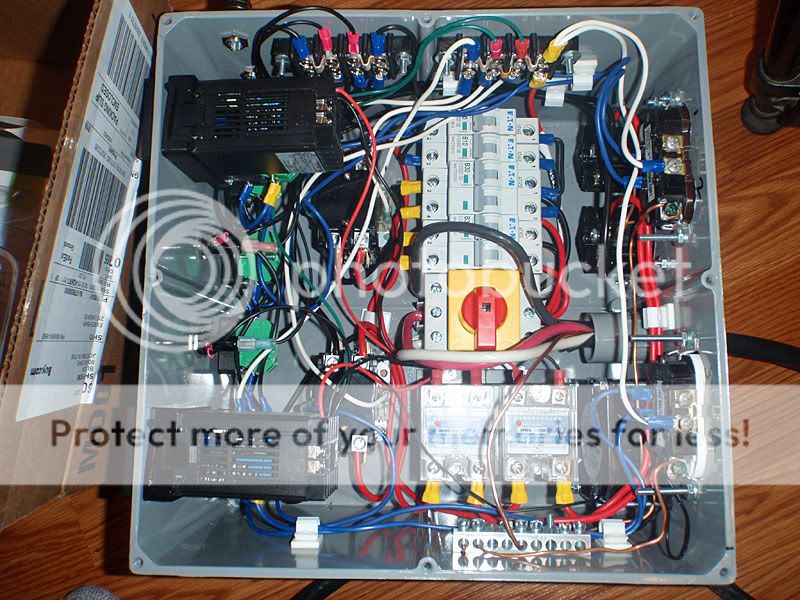
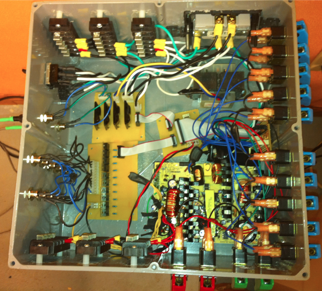
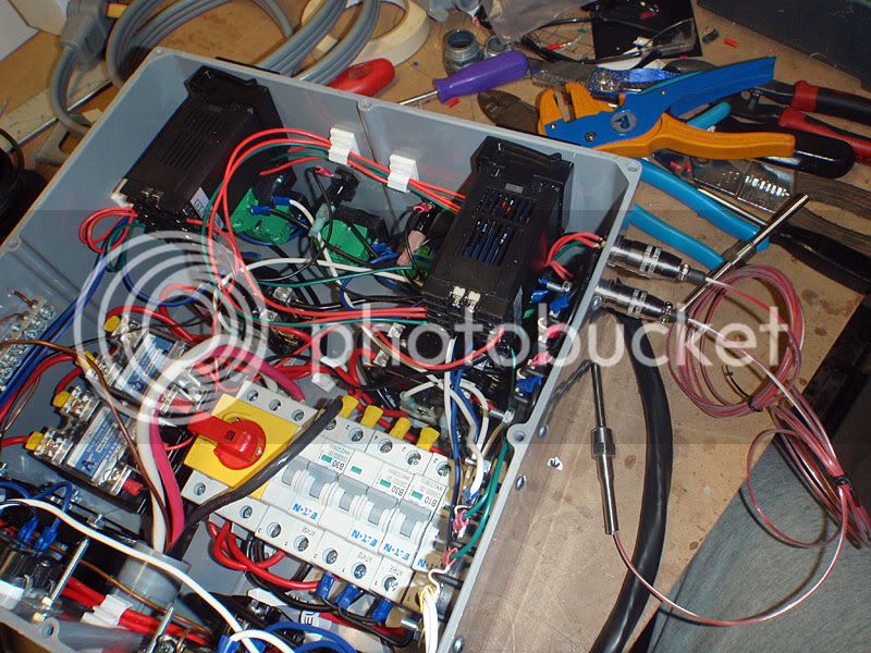
Thank you, and thanks Tiber for your comment. My dad is an automotive wiring guru, so I guess I get my anal-retentiveness for neat wiring from him. It also makes me feel better that everything's where it belongs when working with 50 amp service.That is a super clean control box. I recognize the PID's, very good and great value. I am impressed how neat and clean your wiring is. Nice work.
Thanks! We'll be expecting pictureslooks great! Great job on the wiring!
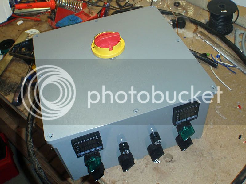
I got my enclosure in today...this is inspiring
...what are the two knobs between the PIDs?
Question for ya:
Are you cutting your existing RTD wires to split for use inside and outside the box, or are you buying additional wire to use between the PID and the internal panel mount RTD connectors?
I was thinking about what to do with mine, and there's pretty much no way to avoid having to recalibrate the RTD with this setup.
TB
I'm probably using additional wire. I've got a bunch of 18gu that I've been using for the low amperage bits of the circuits. I figured I'd want to calibrate the RTDs anyway, so it doesn't really matter. I believe the PIDs have provisions for calibration built in.
-Joe
My bold.I may be wrong but I thought that as long as you used the same type and length of wire, there is no need to recalibrate with the 3 wire RTDs. Anyone know any different?
I'm interested in this as well.I know the Watlow PIDs I have can be re-calibrated but I don't thinks it's as simple as setting an offset. The manual shows a script where you apply a set voltage/resistance with a decade resistance box to calibrate. This seems a little beyond the tools I have. Has anyone out there actually calibrated a PID this way?
My bold.
That's the problem. Both Joe and I are extending the RTD wires and splicing in some panel mount connectors, which changes the resistance of the wires going to the PID. Wouldn't that throw off an RTD by a tad?
I'm interested in this as well.
TB


