• Please visit and share your knowledge at our sister communities:
  • If you have not, please join our official Homebrewing Facebook Group!

    Homebrewing Facebook Group

Electric brewery build

Homebrew Talk

Help Support Homebrew Talk:

This site may earn a commission from merchant affiliate links, including eBay, Amazon, and others.
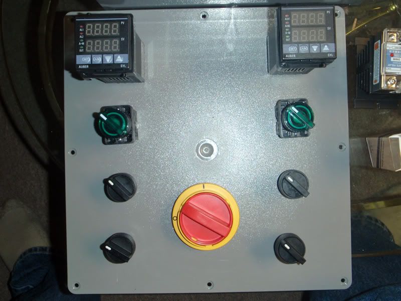
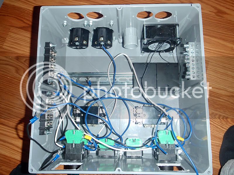
Thanks, that looks very similar actually. The only real differences appear to be that you're switching the power to the PIDs separately and have two, 120v circuits. Thanks for that!

-Joe
 
Oh one other difference: you're powering the PIDs with 120v off those separate circuits, which is what I had originally planned. However, the wiring diagram in the instructions shows taking 240v off the load leads:

pidwiring.jpg

Think it matters?

-Joe
 
Ok. Do you find a need to switch the PIDs off individually? I was just going to use the master disconnect to shut everything down when I'm done. Can the PID be turned into thermometer-only mode, like for when I'm chilling? I was thinking I'd have to switch it to manual mode then turn it all the way down.

-Joe
No. I drew the diagram the way Tiber_Brew wanted it. The PID will register temperature all on its own as long as the temp probe is connected. BTW, it's my understanding that the PID will not function if a probe is not connected. (I'll have to test that when I get a chance.) For a temp probe, just don't use the controllers output for the elements.
 
Ooooo I thought Tiber_Brew was the name of your system, not a person :eek:

Ok, I think I'm going to go with this. The switches I'm using call for 10A circuit protection (which will still be plenty), so I added two circuits there. I also moved the contactor *before* the SSD so the SSD will be cold with the switch off.

wiring.jpg

-Joe
 
Joe,

I'd do it that way with a small change:

nostalgia-wiring-1.jpg


This way you protect the PID with a small fuse and also leave it powered up when you power down the heating elements. This will allow you to use the PID temp probe during cooling. Also - I changed your PID power scheme to 120V to eliminate 1 fuse and have the PID power available when the element contactor is not delivering power to the element.

Anyway, just some ideas. I really don't mean to jump on your process and for that I sincerely apologize.

Paul
 
Anyway, just some ideas. I really don't mean to jump on your process and for that I sincerely apologize.
No need for apologies; this is exactly the kind of input I was hoping for!

As for the wiring, that was my mistake - I did intend to take power for the PID from before the contactor so it stays on during cooling. Thanks for the tip about the fuse, too.

-Joe
 
Joe,
I started following (suscribed to it) your thread when you posted pictures of your kettle fixtures and the technique you used to attach fittings. I just plain love the method of how you are doing it. I'm a huge advocate of Harris Stay-Brite solder. I have made many setups for friends over the years using it. I got into making custom fittings for electric elements and even bought a hobby mini lathe to accomplish the task.

DSC01565-e.JPG


DSC01571-s.JPG


DSC01585-e.JPG


DSC02376-cr.jpg


DSC02392-s.jpg


Anyway, I'm tipping a brew in salute to you.
If there is anyway that I can help you, just let me know.

Paul (P-J)
 
More parts show up. Working on layouts. Will I need to expose the SSR's heatsinks to ambient air somehow?

controlbox_outside.jpg


controlbox_inside.jpg


-Joe
 
More parts show up. Working on layouts. Will I need to expose the SSR's heatsinks to ambient air somehow?


-Joe

I suppose a little 2" muffin fan with an vent on the other side wouldn't be a bad idea. That's what I've been figurin anyway.

Off topic: As much as I anticipate the union electrician voice of reason and warnings of self destruction, I question the practical need for the additional 30 amp breakers. I understand the logic behind it, wire protection. It makes perfect sense in a permanent installation that is in service 24/7. How often are these rigs run unattended for long periods where a short run of 10/3 SJ to the element overheating would be catastrophic? Maybe it's a moot point if you found them cheap but... yeah, I'm a cheap bastard.
 
Mmm, muffuns. I was thinking the same, but I was concerned about all that damp air blowing around. Although I guess as long as the air is moving it shouldn't be an issue.

-Joe
 
zomg I just want to plug this thing in to see it light up :D :D

controlbox_front.jpg


controlbox_back.jpg


-Joe

Looks like you're about where I'm at! I'm currently sanding/painting mine, then I'll get started wiring.

Scroll down through these pics, and you'll see some similarities.

By the way, I'm the guy Paul (P-J) gave control panel advice to. He's a real helpful guy, and very knowledgeable, so don't be afraid to ask him about your wiring if you're not sure.

We could probably mutually benefit from each others' electric brewery build threads. It looks like your setup will be pretty close to mine. And we're at about the same progress right now.

Good luck my friend!
TB
 
Looks nice, Tiber! I decided to keep everything in the box instead of on the lid, as originally planned. It actually worked out to give me more space (since the PIDs are so deep, there's more space under them if they're placed horizontally) and as a bonus I don't have to deal with any wires if I take the lid off.

Speaking of wires...it has begun. Things get tight in there FAST.

control_wiring1.jpg


-Joe
 
I doubt it will be an issue, but you'd get better airflow/cooling if you rotate those heatsinks 90 degrees.

+1 for this - it's definitely worth doing if it's possible as the air will travel through the fins and cool them much more efficiently.

I wish I could find some of those cool industrial switches here in the uk!

Keep up the good work:)
Henry
 
Yes, I wanted to rotate them, but they got uncomfortably close to the contactors and the fan. I'll have to try again now that everything is bolted down.

As for holes: for the big round ones I used holesaws. Not really the best for plastic - they tended to wander and make an oversized hole.

For the switch holes I used a Forstner bit, which worked quite well. I deburred the hole with my step drill (the steps aren't deep enough to make a through hole in this plastic).

For the square and fan holes I used a Dremel tool and hand files.

-Joe
 
Back
Top