• Please visit and share your knowledge at our sister communities:
  • If you have not, please join our official Homebrewing Facebook Group!

    Homebrewing Facebook Group

ebay aquarium temp controller build

Homebrew Talk

Help Support Homebrew Talk:

This site may earn a commission from merchant affiliate links, including eBay, Amazon, and others.
Thanks for the offer. I found an old laptop charger that is 110v to 12v 1A. I am going to use that in place of the 220v transformer.

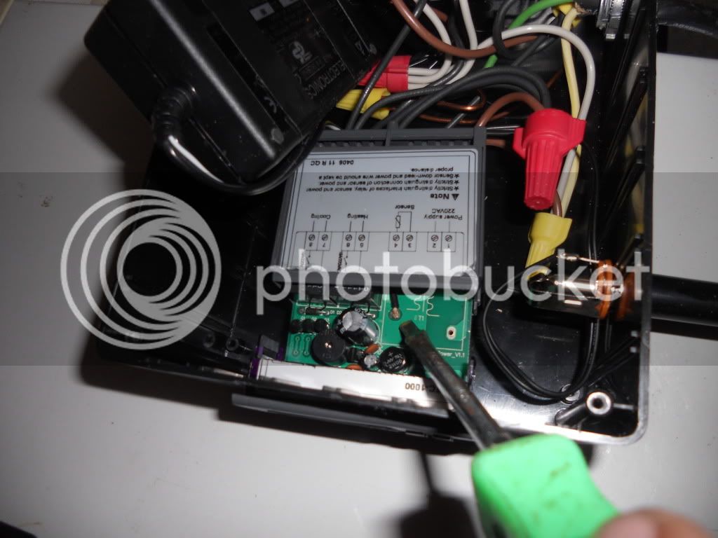
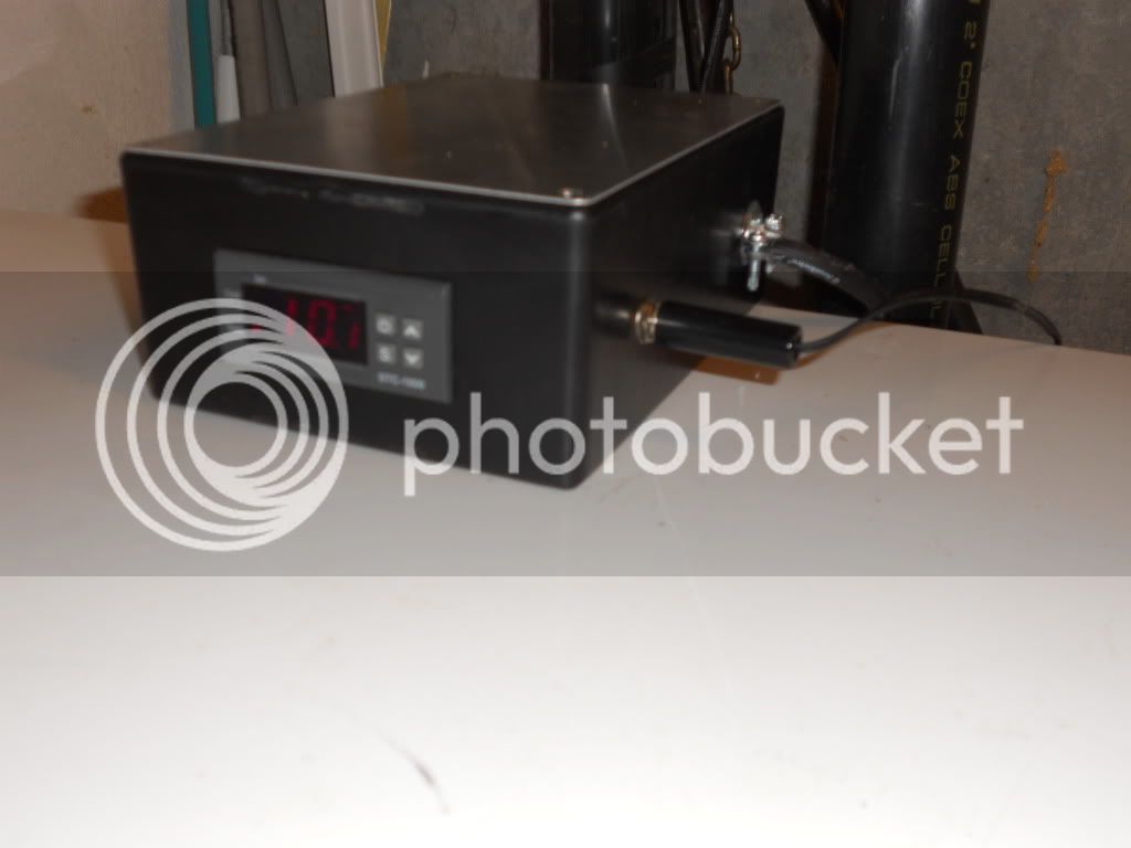
In response to the whole transformer issue. I too purchased the 220V version and decided to run an external transformer as opposed to resoldering one back on to the board. I hoard old electrical devises, a trait passed down from my Dad. I was able to recycle a headphone jack for my NCT temp probe from an old stereo, a 14/3 cord from an old microwave, and a 110V to 12V 1A power pack from an old laptop. I desoldered the 220V transformer from the board of Ebay controller and soldered the wires out of the laptop charger to the board on the output side of old tranformer. I have had this running in the garage for 6 weeks now and it is working well. I also scored the freezer for free!

DSCN2266.jpg


DSCN2267.jpg
 
so I can't find the answer in the thread (and I'm probably just showing my utter lack of grasp of electronics), but how exactly do I connect the wires to the RS relay to have a fan shut on and off with both cooling and heating?

Sorry for the stupid question, but I've been through the thread several times and google is failing me :(.

TIA.
Radio Shack sells many different types of relays. The only way to know how to wire yours is by using the data sheet that came with your relay. This will give you the "pinout".
There has already been one instance in this thread of someone using somebody else's schematic for what was supposedly an identical relay, only to find out the pinout was not the same.

If you are electronically challenged, why not just get another fan, and hook up separate fans to cooling and heating? Simpler, same functionality, and with a built in emergency spare. There are muffin fans hiding in all types of devices that get thrown out, and even if you have to buy one, it isn't much more than a relay.

thanks for the reply. Sorry I wasn't clear. I'm using this one from Radio Shack, and roughly approximating the diagram here. I'm just not sure how to physically attach the wires to the relay.

Thanks again for your help.
 
naiserie said:
so I can't find the answer in the thread (and I'm probably just showing my utter lack of grasp of electronics), but how exactly do I connect the wires to the RS relay to have a fan shut on and off with both cooling and heating?

Sorry for the stupid question, but I've been through the thread several times and google is failing me :(.

TIA.

I use a relay to do the same thing. But it sounds like you might not even have the correct type. The most common relay is known as a Form A or "normally open" (NO) relay, often described as either SPST, or DPST.

But that won't work for your purposes. Technically it's possible to use two of those though. But really, you want a non-shorting (break before make) changeover/transfer relay, which will be SPDT or DPDT.

And then on top of making sure it's the right kind of relay and using the datasheet to figure out the pinout, you need to make sure that not only are the contacts rated for the correct voltage and amps, but that the coil is properly rated as well, since a relay isn't necessarily controlled by the same voltage that it happens to be switching.

Only if you're sure about all of these should you go ahead with it...
 
RS = Radio Shack.
At least that is what I took it to mean. If he knew enough to know which tech jargon term to use for his relay, he would not need to ask how to wire it.

There was an earlier post, or another thread, where a schematic and parts list was given for a heat/cool single fan, relay based solution. I believe the relay spec'd was from Radio Shack. There was also an issue where a person bought, or thought he bought, the correct relay, but the pinout was not the same as the schematic.
 
sorry if I wasn't clear enough and thanks for your help, I've been waiting for a mod to approve my reply to cwi for a few hours. at least that's what the forum software told me...reposting now in case it was a glitch?

I know the pin layout etc, I'm just not clear on how to physically attach the wires to the relay.

relay:http://www.radioshack.com/product/index.jsp?productId=2049721

wiring diagram: http://www.ubermick.com/images/wiring_fermenter_full.gif

Like, is solder the only option? Is there a connector of some kind I can use?

Again, sorry for stupid questions and not spelling it out explicitly. Thanks for your help.
 
cwi said:
RS = Radio Shack.
At least that is what I took it to mean. If he knew enough to know which tech jargon term to use for his relay, he would not need to ask how to wire it.

I know that's what RS means, but I don't necessarily agree with you. I know what the jargon means, but if I don't have the proper datasheet, I'm going to be nearly as in the dark about how to wire it as somebody who knows almost nothing about relays.
 
I know that's what RS means, but I don't necessarily agree with you. I know what the jargon means, but if I don't have the proper datasheet, I'm going to be nearly as in the dark about how to wire it as somebody who knows almost nothing about relays.

This is what caused the confusion-
I've been waiting for a mod to approve my reply to cwi for a few hours. at least that's what the forum software told me...reposting now in case it was a glitch?

I think you were able to see his "unapproved" post somehow, whereas I was not. It just became visible to me while writing this post. Remove his intermediate post from the chain, and your post talks about the type of relay he is using based solely on "RS" from the original post. His original post was also the only post quoted in your post that talked about what type relay he was using, adding to the confusion.

Maybe I couldn't see it because I am on "double secret probation" for my smart ass attitude, or maybe your post count let you see it.

My rationale was that if he was describing which type of relay he had based on the inner workings, he would most likely know to look up the data sheet for the pinouts.
 
I use a relay to do the same thing. But it sounds like you might not even have the correct type. The most common relay is known as a Form A or "normally open" (NO) relay, often described as either SPST, or DPST.

But that won't work for your purposes. Technically it's possible to use two of those though. But really, you want a non-shorting (break before make) changeover/transfer relay, which will be SPDT or DPDT.

I followed his Radio Shack link, and it shows a DPDT 125VAC relay.
Was his link edited, and previously went to a different model?

That relay is more expensive than getting separate fans, even if you buy a DC fan and a transformer. Different strokes, I guess.
 
sorry if I wasn't clear enough and thanks for your help, I've been waiting for a mod to approve my reply to cwi for a few hours. at least that's what the forum software told me...reposting now in case it was a glitch?

I know the pin layout etc, I'm just not clear on how to physically attach the wires to the relay.

relay:http://www.radioshack.com/product/index.jsp?productId=2049721

wiring diagram: http://www.ubermick.com/images/wiring_fermenter_full.gif

Like, is solder the only option? Is there a connector of some kind I can use?

Again, sorry for stupid questions and not spelling it out explicitly. Thanks for your help.

You should be able to find some crimp quick connectors that fit the male lugs on the relay. Soldering may melt the plasticy bits on the relay.
This is turning into a lot of effort to avoid using two fans.
 
If you don't mind going really ghetto, you can thread the wire through the holes in the contacts and bend them around to get the wires relatively secure, and use electrical tape or heatshrink tubing to isolate the contacts and ensure the wire stays in place.

Crimp connectors are an option too. But personally, I would just take the opportunity to learn to solder.

As for why pay more to avoid using two fans, I would do the same. I got my relay for a bit cheaper, but still. I like to keep things neat and even flashy if I can, and using two fans just seems a bit ridiculous, not to mention it ends up using twice the space, and if you've got an ideal spot for a fan, you probably wanna use that for everything.
 
If you don't mind going really ghetto, you can thread the wire through the holes in the contacts and bend them around to get the wires relatively secure, and use electrical tape or heatshrink tubing to isolate the contacts and ensure the wire stays in place.
This method has a high probability of losing contact over time, either by physically loosening, or corrosion working its way into the interface due to the low contact pressure. How long it takes depends on how hostile the environment it is subjected to is. Works great for a quick fix, though.


Crimp connectors are an option too. But personally, I would just take the opportunity to learn to solder.

A small heat sink on the lug may be useful to avoid melting the casing, especially if this is going to be your first attempt at soldering.

As for why pay more to avoid using two fans, I would do the same. I got my relay for a bit cheaper, but still. I like to keep things neat and even flashy if I can, and using two fans just seems a bit ridiculous, not to mention it ends up using twice the space, and if you've got an ideal spot for a fan, you probably wanna use that for everything.
Twice the space? I thought we were talking about <4" inch fans and chest freezers. If an ideal spot existed and space was an issue, the two could be ganged together.

Something flashy would be adding a timer circuit to continue running for a bit after the cooling/heating shut off, and also periodically between cycles. This would be especially effective for cooling since the coils continue to cool for a few minutes after shutoff. Running the fan for a bit during long off periods can help keep faucets cool in keezers.
 
thanks for the info emjay and cwi, the crimp on connector is probably what I'll use for the time being.

money isn't the only factor involved in setting this up and I'll spare you the boring details as to why only one fan.

thanks again.
 
Has anyone tried a brewbelt for the heating cycle. Just wondering if it would work better than a heat light, or not
 
Wild Duk said:
Has anyone tried a brewbelt for the heating cycle. Just wondering if it would work better than a heat light, or not

I have. It works the same, since it's all enclosed anyways. The brewbelt only puts out something like 20W though.
 
And are guys using fans for just keezers, or fermentation fridges, or for both.... I just got my chest freezer off CL, got the controller, now just need to get it all together....I just plan on it to ferment and lager
 
Has anyone tried a brewbelt for the heating cycle. Just wondering if it would work better than a heat light, or not

Just keep in mind that they don't recommend using brew belts on a carboy. If you ferment in plastic on stainless, you should be good.
 
Is one big computer fan mounted on the bottom of the chest freezer lid enough, or maybe a small 120v fan and just put in on the "step" which is inside the freezer..... It's a 7.0 cf type freezer
 
Is one big computer fan mounted on the bottom of the chest freezer lid enough, or maybe a small 120v fan and just put in on the "step" which is inside the freezer..... It's a 7.0 cf type freezer

I built a ferm chamber a few month back with a 5.0 cu ft G.E. freezer. I didn't use a fan for any sort of circulation and a simple 25W bulb as a heat source. So far, I haven't seen any need for anything more elaborate after a half a dozen batches...temp is controlled to within +/- 1 degree F and the freezer runs for about 7-8 minutes every hour and half. I came to the conclusion that it's a small enough area that natural circulation works just fine.

Just my $.02

If you wanna see some pics of my project...the link below will take you to it.
My Keezer Project
 
Wild Duk said:
Is one big computer fan mounted on the bottom of the chest freezer lid enough, or maybe a small 120v fan and just put in on the "step" which is inside the freezer..... It's a 7.0 cf type freezer

I thought I'd post my experience here. To allow 4 pin locks and 1 ball lock fit in my keezer I built a stand to carry the height of the hump all the way across my keezer floor. I had a fan blowing the air around the keezer but it only circulated air around the top and the cold air really stayed at the bottom. I made a fan the sucks cool air from the bottom and exhausts to the top using a 2L bottle, a PVC tube and some duct tape. The hoses at the top are noticeably cooler now and condensation has been reduced quite a bit as well. My suggestion is to make sure you circulate air from the bottom to the top. Now, if I had not made the stand, I may not have had the issue I did. My 2 bits.

EDIT: Yes, that looks ghetto as hell, but it works great!

image-222841058.jpg


image-2194164636.jpg


image-4166493830.jpg
 
I thought I'd post my experience here. To allow 4 pin locks and 1 ball lock fit in my keezer I built a stand to carry the height of the hump all the way across my keezer floor. .

That is probably a good idea in general. I may be able to fit 4 ball locks in a 5cuft GE freezer that I am getting ready to build.
 
Just wanted to thank the OP for the diagram and pics, I got mine finished and working in about an hour. Going to calibrate tonight and get a couple batches in the fermenter this weekend.
 
That is probably a good idea in general. I may be able to fit 4 ball locks in a 5cuft GE freezer that I am getting ready to build.

4 is a tight squeeze with a collar. You can get 4 + a 5# CO2 tank if you don't mind slightly denting the interior wall as you cram the tank in place. The stand isn't needed, but one of the kegs will hang halfway off of the hump.
 
I get one of these, but before I buy freezer I was thinking maybe I can use it for setting temperature of water in HLT, if it is good I"ll buy another one for fermentation control.
What do you guys think, can it be done and how would sensor react in 90° C water?
Also is it accurate enough so we can rely on it while mashing/sparging?
 
I get one of these, but before I buy freezer I was thinking maybe I can use it for setting temperature of water in HLT.
What do you guys think, can it be done and how would sensor react in 90° C water?
Also is it accurate enough so we can rely on it while mashing/sparging?

I would not trust the cheap plastic covering the sensor in 90 deg C water. You would likely get some chemical leeching. Could be wrong but I wouldn't risk it myself.

I used a home depot temperature probe with similar plastic covering in my first AG brew day and it kinda melted... Threw that water out and started over with an analog thermometer.

Also if you calibrate the probe with ice water at 0 deg C it will be accurate near freezing. There may be some non-linearity up near boiling temperatures. Best way to test that would be to calibrate it with ice water (0 deg C) then boil water and see how far off you are - but again... chemical leeching.
 
Hmm.. I"m too afraid that it will melt.
I have K-type thermometer with metal probes, maybe I could connect this one instead of default sensor, but I"m not sure is there a difference between wires in them..
 
Back
Top