Well done! I have been looking to build something like this for a long time. This is perfect for my purposes. I am basically going to clone this build. I really want to thank everyone for contributing to this thread (and to all the others like it). This has given me the confidence to get started on my own setup (and my tax return has given me the funds fortunately).
P-J, I too need your assistance, please. There is at least one change I'd like to make to that wiring diagram: I don't really need for the extra LED push button switches for the elements. The other two seem easier since they don't need contactors, so I'll leave those in place. Removing those push button switches and the contactors seems to simplify the wiring and free up room in what looks to be a crowded enclosure. I like the extra room since my wiring work isn't the best.
If I were to do that, could I use some 20a 120v toggle switches of some sort? Maybe like this one?
http://www.amazon.com/Heavy-Duty-Toggle-Switch-SPST/dp/B0002ZPBRA/
HopRodGR mentioned this in post #90, and iijakii mentioned a basic outlet/switch combo in post #91. I like that too, but it seems like the single outlet handy box just barely fit on the enclosure, and I don't really want a larger one hanging off the side if possible. I guess I could always mount the SSRs and heatsinks to the top instead of the back to make everything fit.
With the two combo outlets in mind, I tried modifying your diagram. Does that seem close? How might toggle switches fit in to that diagram?
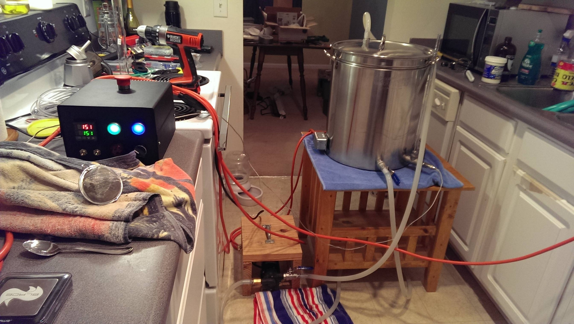
Really my goal is function over form, and I'm trying to clone this build while trimming certain bits for economy (camlocks, sight glass, etc.).
Any advice you might have for me would be most appreciated!