• Please visit and share your knowledge at our sister communities:
  • If you have not, please join our official Homebrewing Facebook Group!

    Homebrewing Facebook Group

Double check my wiring diagram?

Homebrew Talk

Help Support Homebrew Talk:

This site may earn a commission from merchant affiliate links, including eBay, Amazon, and others.

Ahks

Well-Known Member
Joined
Nov 8, 2011
Messages
71
Reaction score
17
Location
Southeast Michigan
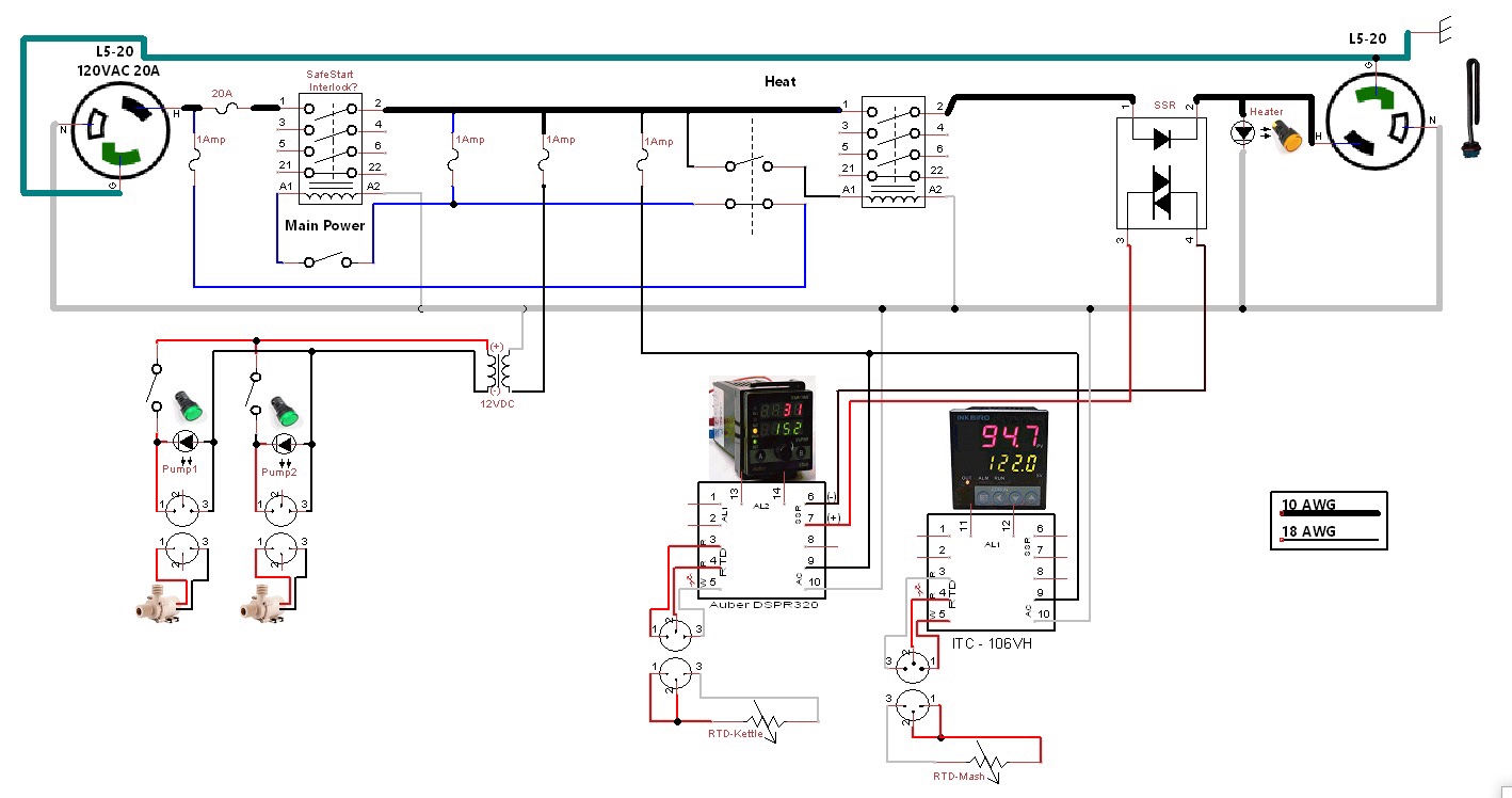
System is a 120V 20A on a dedicated circuit with a 20A GFCI. It uses a 2.2kW element for 2.5 - 5 gallon batches.
Setup is 2 vessel similar to the BrewEasy design using similar kettle geometry to a Grainfather since I know they don't have too much trouble boiling wort for 5 gallon batches on 120V. I'm leaving myself the option for 2 pumps, but I'll probably only use 1 most of the time.

Since I'm looking at Auber's DSPR320, I'll probably spend some time programming it and therefore the panel will probably be on when the system is dry. I think I worked in a safe start to prevent a dry fire on start up. Not worried about the pumps. They're noisy enough to let me know if they're on, the element, not so much.

Anything missing? Any complaints? See something stupid?
7e8258de-35a6-44c5-9173-202af034026f.jpg
 
System is a 120V 20A on a dedicated circuit with a 20A GFCI. It uses a 2.2kW element for 2.5 - 5 gallon batches.
Setup is 2 vessel similar to the BrewEasy design using similar kettle geometry to a Grainfather since I know they don't have too much trouble boiling wort for 5 gallon batches on 120V. I'm leaving myself the option for 2 pumps, but I'll probably only use 1 most of the time.

Since I'm looking at Auber's DSPR320, I'll probably spend some time programming it and therefore the panel will probably be on when the system is dry. I think I worked in a safe start to prevent a dry fire on start up. Not worried about the pumps. They're noisy enough to let me know if they're on, the element, not so much.

Anything missing? Any complaints? See something stupid?

View attachment 605666
Looks pretty good to me. I don't know how you would integrate the safe start with the dc motors even if you wanted to. If you could mix the contact blocks on a DPST NO NC switch with AC and DC, you could run the safe start line through the NC block and as long as that is closed the main contactor/relay coil would get power.
 
If you're only doing safe start on a single relay/load it seems to me like there might even be a simpler solution. Would have to defer to the pros on this one
 
If you're only doing safe start on a single relay/load it seems to me like there might even be a simpler solution. Would have to defer to the pros on this one

Using the safe start interlock that i learned from @doug293cz its just some bits of wire and a couple fuses. That looks to be what OP did here.

Also, OP you may be able to get away with one less fuse in your panel by sharing the fuse between the motors and the EZboil/PID. I think between those two controllers you're talking .5A. How much load do those DC motors draw?
 
Using the safe start interlock that i learned from @doug293cz its just some bits of wire and a couple fuses. That looks to be what OP did here.

Yep. Worked out the latching relay logic and just cloned the loop off one of his 2 element/240V schematics

Also, OP you may be able to get away with one less fuse in your panel by sharing the fuse between the motors and the EZboil/PID. I think between those two controllers you're talking .5A. How much load do those DC motors draw?

Good call.

Motors are 12VDC 0.7A each. Planning on using a 3A 12VDC supply that I think draws a half amp of 120V. I think you're right that those controllers only draw a quarter amp each...

It'd be easy to wire it with one less fuse... And add another if firing up the second pump (if I use it) pops it [emoji14]
 
Also, I cant tell from the diagram, but if it's me I would make sure i used an L5-20r (receptacle) for the power input, and an L5-20p (plug) for the element output. I know its probably common sense not to plug them in wrong, but this would _prevent_ someone (perhaps not you) from plugging them in wrong.
 
Also, I cant tell from the diagram, but if it's me I would make sure i used an L5-20r (receptacle) for the power input, and an L5-20p (plug) for the element output. I know its probably common sense not to plug them in wrong, but this would _prevent_ someone (perhaps not you) from plugging them in wrong.
NO, NO, NO! Power input must always be a plug, and power output always a receptacle. Power output on a plug risks having exposed voltage on the plug tines.

Brew on :mug:
 
Looks good. What relays are you using?

Brew on :mug:

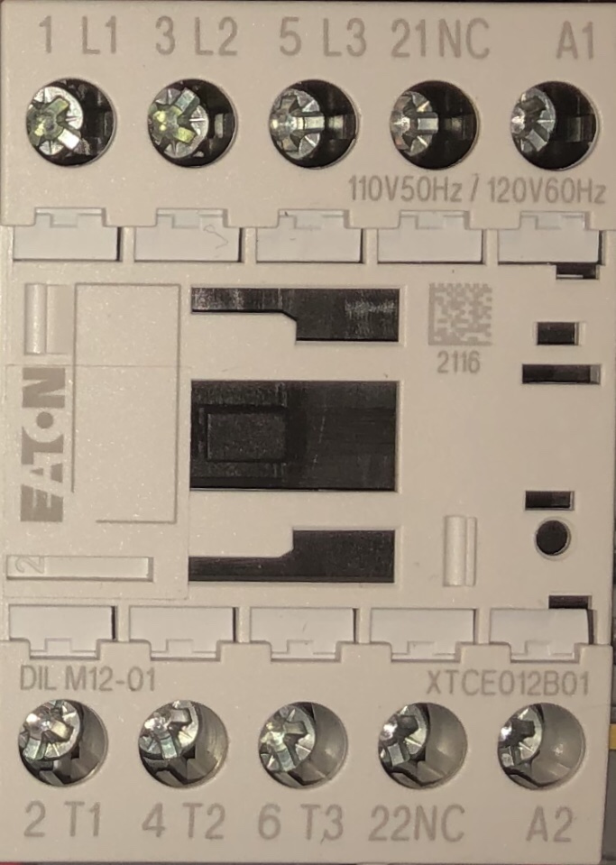
I have the benefit of working for a company that does automation safety engineering and consultation. So I am using a few Eaton DILM12-01 relays that some engineer bought for a project then replaced with safety rated relays for some spec that the Eaton's couldn't be certified for.
If I've read the spec sheets properly, they can handle a 20A resistive load as long as you're only using one contact.

IMG_2457.jpg


NO, NO, NO! Power input must always be a plug, and power output always a receptacle. Power output on a plug risks having exposed voltage on the plug tines.

Brew on :mug:

This is what I'm doing. Anything that can hurt me is a recepticle (female plug). The pump connects I think have male bulkhead fittings, but they have a cap... And probably won't hurt me unless I stick my tongue to em. [emoji14]
 
NO, NO, NO! Power input must always be a plug, and power output always a receptacle. Power output on a plug risks having exposed voltage on the plug tines.

Brew on :mug:
Yeaaaaa I got those two backwards, oops! Thanks for correcting me.
 
This is what I'm doing. Anything that can hurt me is a recepticle (female plug). The pump connects I think have male bulkhead fittings, but they have a cap... And probably won't hurt me unless I stick my tongue to em. [emoji14]
Pumps are 12V, and 12V can't hurt you, unless you have a high current supply and short a ring or something across the contacts.

Brew on :mug:
 
Wow. There are multiple issues with that diagram.
1) The SSR has 120Vac connected to its input. This needs to be powered from a few volts DC! (Or have you merely confused the input and output of the SSR?)
2) The heater indicator LED is powered from 120Vac - LEDs work on extra low voltage DC
3) You want to use plugs where you need receptacles! Doesn't matter if it has a cap - this is DANGEROUS and I would say illegal, even in USA. (If I did this sort of thing I would be prosecuted and lose my electrician's licence!)
4) Your motors are 12VDC, and yet they are powered from a transformer. No rectifier? How is the AC going to become DC if there is no rectifier?
You really need to have a qualified and licensed electrician wire it up for you. Is it even legal for someone other than an electrician to do electrical work? It's not allowed in Australia or New Zealand - thank goodness!!!
 
Thanks for your input Barry, welcome aboard.
This thread is a year old, so probably resolved. Enjoy the site, feel free to join the conversation, keep us posted on your brewing.
 
Wow. There are multiple issues with that diagram.
1) The SSR has 120Vac connected to its input. This needs to be powered from a few volts DC! (Or have you merely confused the input and output of the SSR?)
OP has the SSR symbol upside down in the drawing, but the terminal numbers are correct for most SSR's (1&2 are the AC power leads, and 3&4 are the control inputs.)
2) The heater indicator LED is powered from 120Vac - LEDs work on extra low voltage DC
There are packaged LED indicator lamps that are designed to be powered from 120V & 240V AC supplies. They have internal circuitry to provide the voltage and current limiting required by the LED.
3) You want to use plugs where you need receptacles! Doesn't matter if it has a cap - this is DANGEROUS and I would say illegal, even in USA. (If I did this sort of thing I would be prosecuted and lose my electrician's licence!)
OP has proper plug/receptacle usage on the AC circuits. Doesn't matter what is on the 12V DC circuits, as you can't get a shock at that voltage.
4) Your motors are 12VDC, and yet they are powered from a transformer. No rectifier? How is the AC going to become DC if there is no rectifier?
You really need to have a qualified and licensed electrician wire it up for you. Is it even legal for someone other than an electrician to do electrical work? It's not allowed in Australia or New Zealand - thank goodness!!!
I assume that OP just didn't have a suitable symbol to use for a DC power supply.

Doing your own electrical work is legal in many venues in the USA. And I think building electrical devices that are not hardwired into the structure wiring is legal everywhere in the USA.

Brew on :mug:
 

Latest posts

Back
Top