DIY Dual Chugger Pump Switch Box

Homebrew Talk - Beer, Wine, Mead, & Cider Brewing Discussion Forum

Help Support Homebrew Talk - Beer, Wine, Mead, & Cider Brewing Discussion Forum:

This site may earn a commission from merchant affiliate links, including eBay, Amazon, and others.

Do you plan to use this DIY?

  • Yes I am going to do this soon

  • I'm thinking about it, but not right now

  • No, it'll void the warranty or I'm not comfortable


Results are only viewable after voting.

johnwpowell

Well-Known Member
Joined
Dec 27, 2016
Messages
258
Reaction score
70
I haven't seen a lot of DIYs on chugger pump switches short of a full electric brewery control panel. Plugging and unplugging the pumps is a pain--they should be designed with an inline switch. Here's how I created a switchbox for my 2 chugger pumps.

Parts List

Tools List

Instructions
  • Plug the 3 unused holes at the top and the 1 unused hole at the back of the enclosure with the supplied hole closure plugs
  • Drill holes to mount the enclosure. I drilled 4 holes at the back to screw to my brewing table. Use a center punch to mark and a metal drill bit slightly larger than the screws you plan to use
  • Mount the enclosure using screws/hardware of your choice
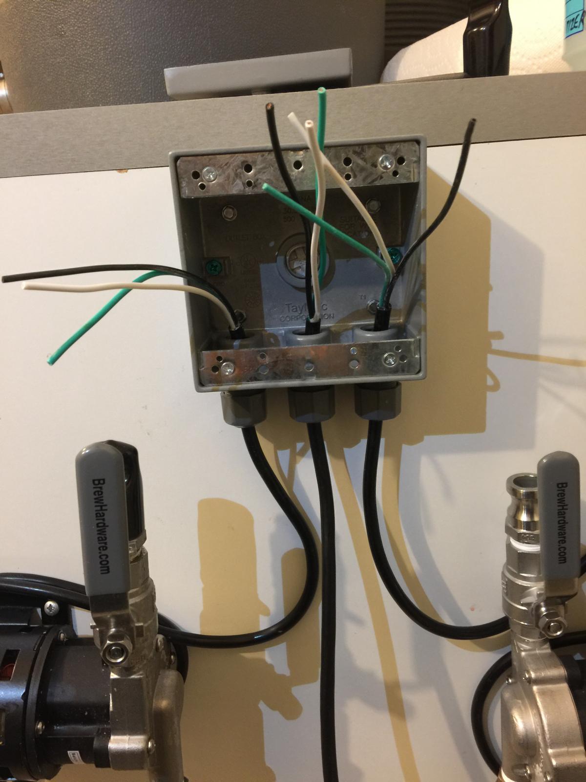
  • Remove and discard the metal nuts from the waterproof cord connectors and thread into the 3 bottom holes of the enclosure
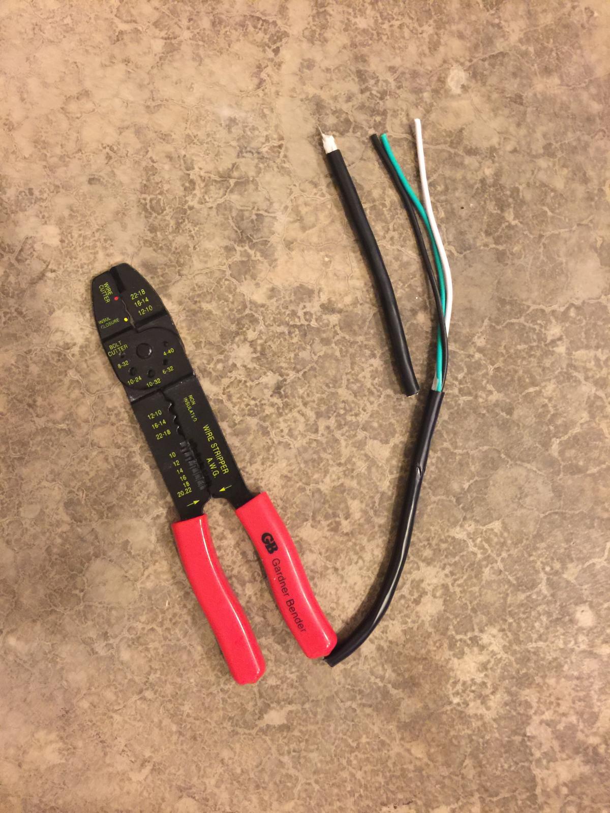
  • Cut the female plug off the extension cord
  • Cut 1' off the extension cord, carefully remove the outer jacket and sit the wires aside (you will use the wire for jumpers in the next steps)
  • Carefully strip 6 inches of the extension cord outer jacket to expose the 3 wires
  • Feed the extension cord wire into the middle connector and tighten
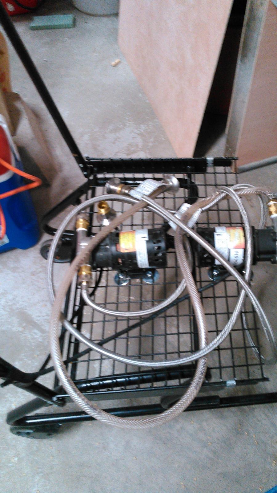
  • Cut the male plugs off the chugger pumps, carefully strip 6 inches of the outer jacket and feed into the left and right connectors respectively and tighten
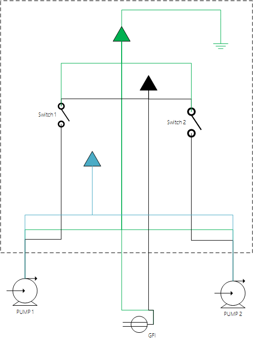
  • Use the diagram below to wire the switch. Note I used blue to indicate the neutral (white) wire since the diagram background is white
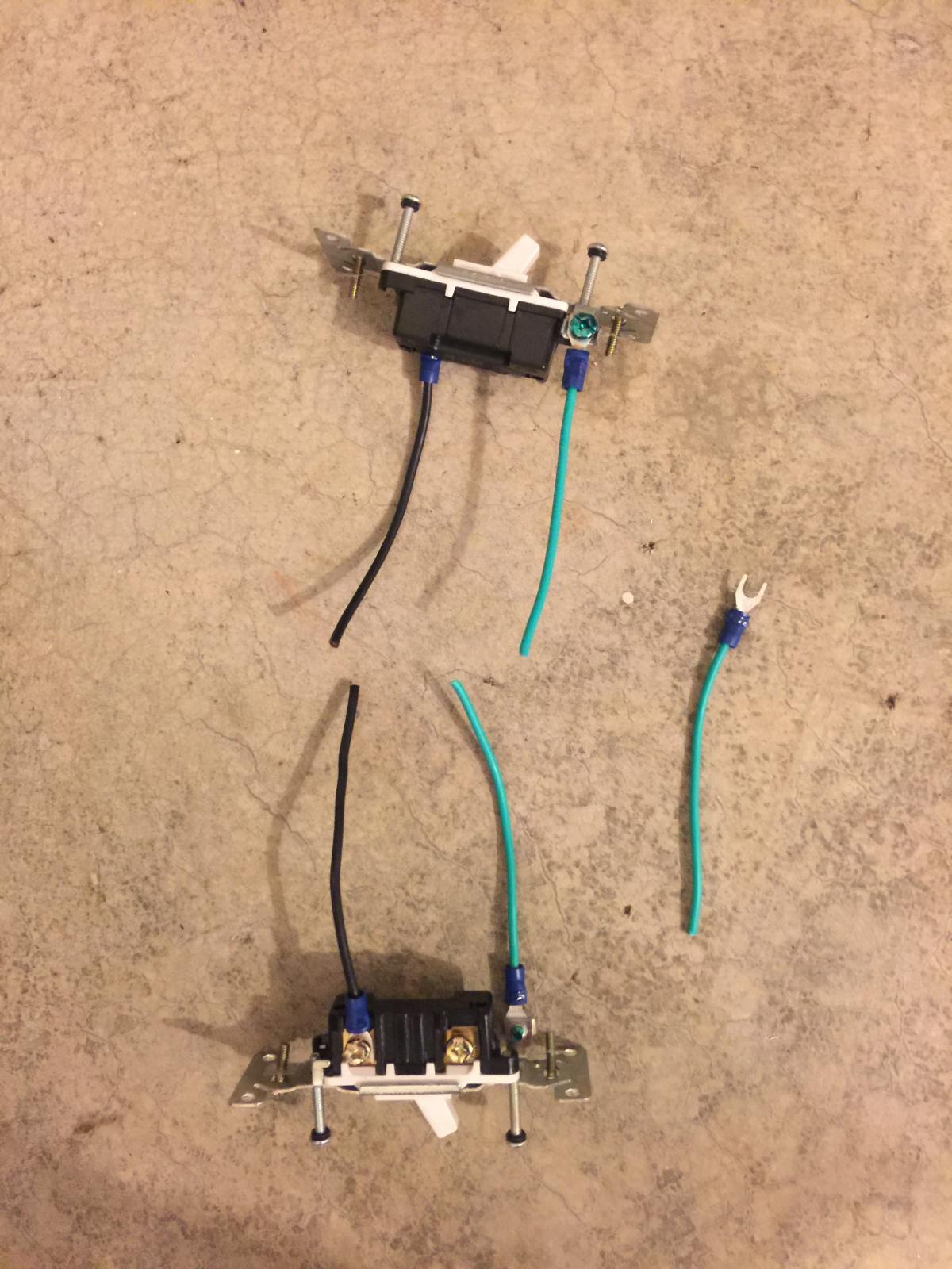
  • Cut three 4" length green jumper wires from the 1' extension cord
  • Strip 1/2" of insulation from each end of the 3 green jumper wires and crimp a spade connector on one end
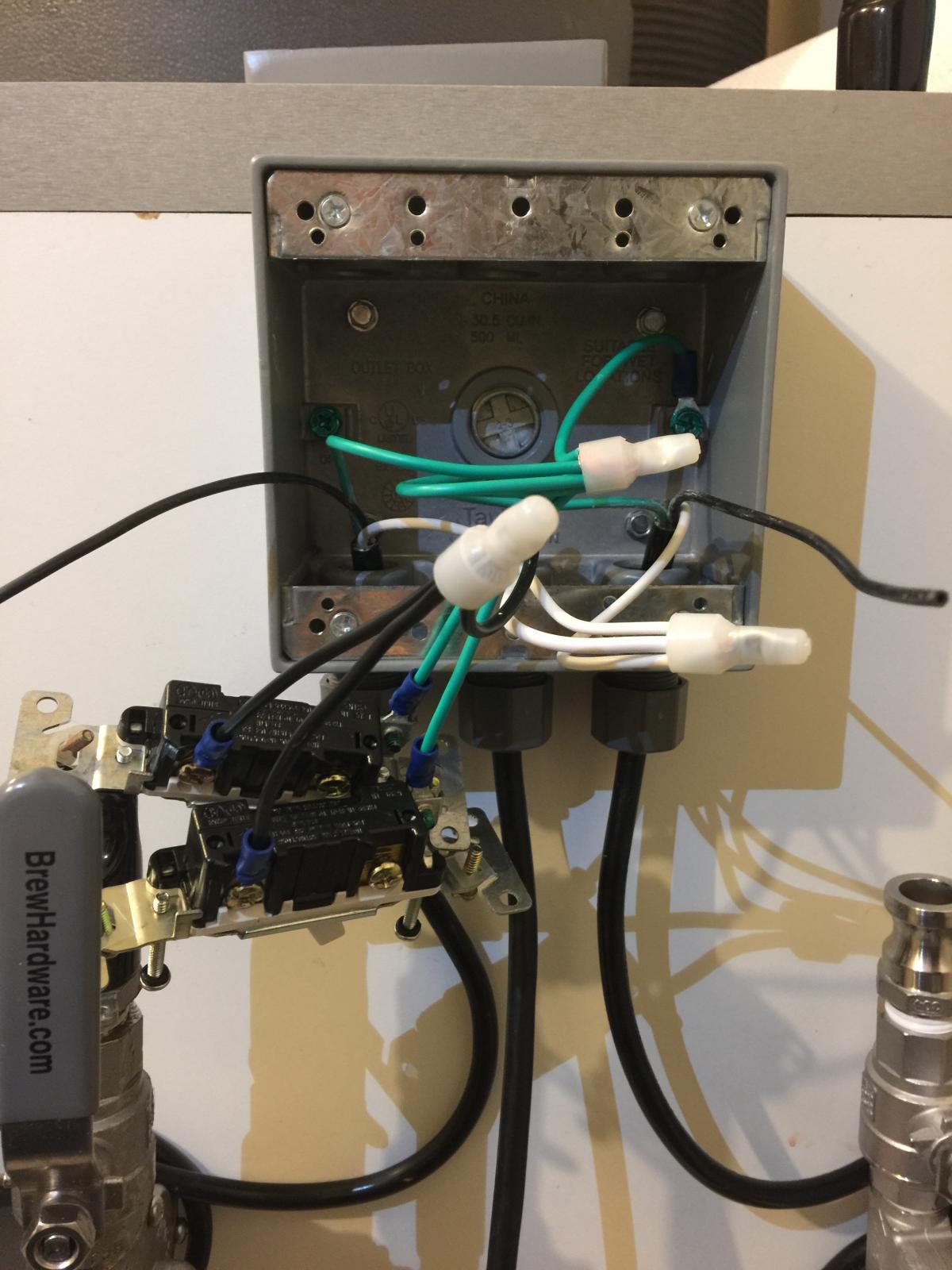
  • Strip 1/2" of insulation from each of the 3 green wires from the extension cord and pumps together along with the 3 jumper wires and crimp in a closed end splice connector
  • Attach one green jumper wire to the green screw in the enclosure
  • Attach the other green jumper wires to the green screws on each of the switches
  • Strip 1/2" of insulation and twist the 3 white wires together and crimp with a closed end splice connector
  • Cut two 4" lengths of black wire from the 1' extension
  • Strip 1/2" of insulation from each end of the jumper wires and attach a spade connector to one end
  • Strip 1/2" of insulation and twist the 3 black wires from the incoming extension cord along with the 2 jumper wires and crimp in a closed end splice connector
  • Attach the black jumper wires to the top of each switch
  • Strip 1/2" of insulation from the black wire from each of the chugger pumps and crimp a spade connector on it
  • Connect the black wires from the chugger pumps to the bottom of each switch
  • Install switches in box being careful to push wires in so they are not too crowded
  • Install the gasket (it will help you to know when the screw holes are lined up properly)
  • Install the cover (note: you don't need the horseshoe connectors that come in the kit)
  • Ensure the switches are in the off position
  • Prime the pumps
  • Plug into a GFCI outlet and test

PumpSwitch.png


jumper.jpg


wires.jpg


switches.jpg


wiresconnected.jpg


gasket.jpg


switchbox.jpg
 
Last edited by a moderator:
I did something similar for my pump setup however instead of cutting off the end of the pump cord I built an outlet controlled by a switch. I plug the outlet into my wall to give it power and plug the pump into the outlet. It achieves the same outcome as this project I just didn't want to cut the end of the pump cord off because I thought at some point I'd sell it and not many people would want to buy a pump without a functional cord.
 
Thanks a ton for posting! This is the most detailed writeup I've found, thanks!

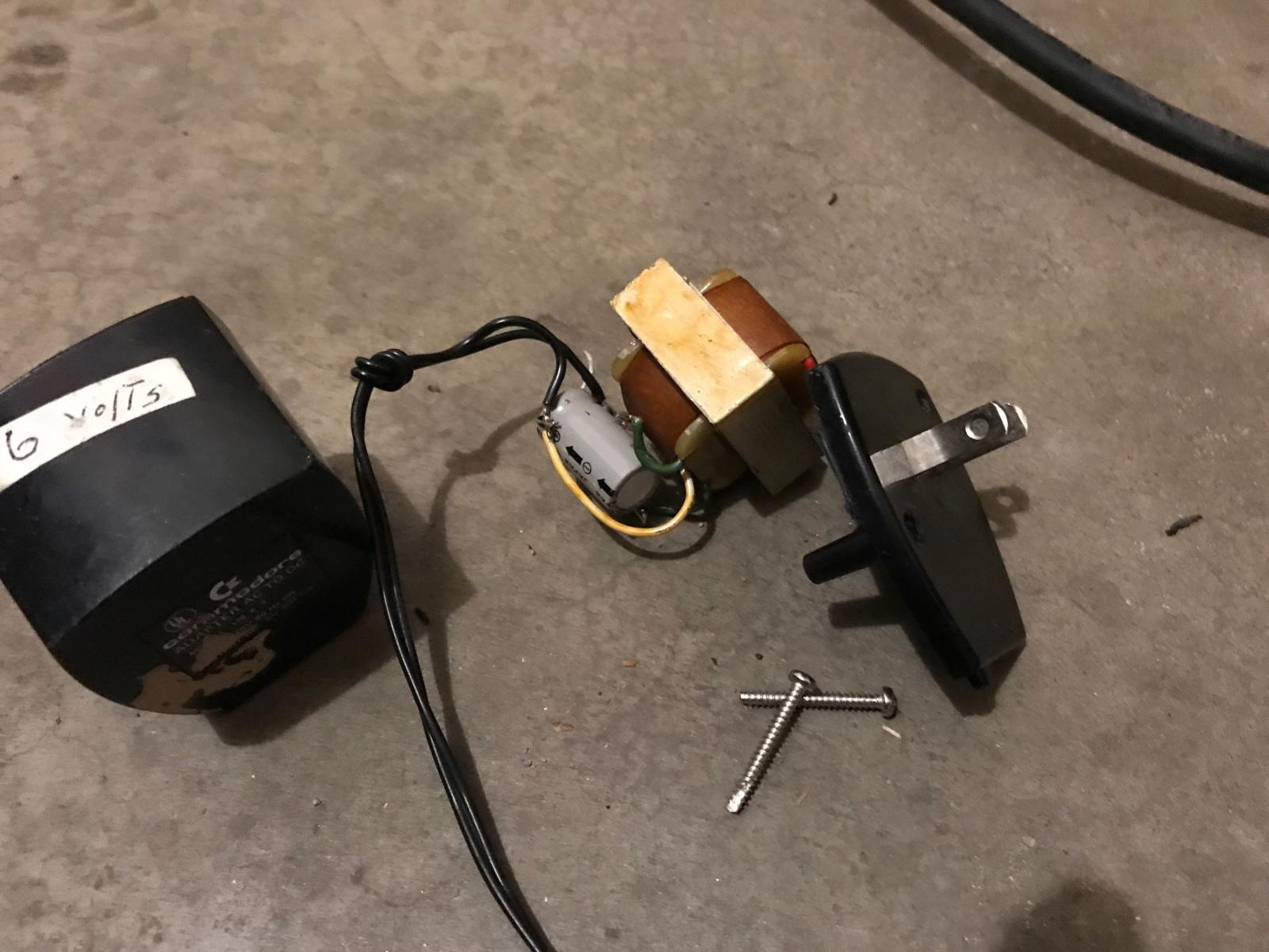
One additional question: I've got a couple digital thermostats (link below) that I'd like to try and mount on this toggle switch faceplate. It looks to me like these take 7-30V power and I'm not sure how to step that down from the 120V. Currently I'm running them off of a 6V power supply (see attached picture) and the only thing I can think of is to run the power through these components to output 6V. Unfortunately, I don't see any way to fit these components in this small box. Any ideas?

https://www.amazon.com/gp/product/B00L0SS8QO/?tag=skimlinks_replacement-20

51396777185__10079D8A-4461-4A76-9CD5-568D6AEEDDF5.JPG.jpg
 
Last edited by a moderator:
Thanks a ton for posting! This is the most detailed writeup I've found, thanks!

One additional question: I've got a couple digital thermostats (link below) that I'd like to try and mount on this toggle switch faceplate. It looks to me like these take 7-30V power and I'm not sure how to step that down from the 120V. Currently I'm running them off of a 6V power supply (see attached picture) and the only thing I can think of is to run the power through these components to output 6V. Unfortunately, I don't see any way to fit these components in this small box. Any ideas?

https://www.amazon.com/gp/product/B00L0SS8QO/?tag=skimlinks_replacement-20

I should put together an alternate setup with outlets rather than hardwiring. This way you could plug the transformer in directly and not have to cut wires on your chugger pumps or disassemble transformers. Let me do some research.
 
Last edited by a moderator:
Thanks a ton for posting! This is the most detailed writeup I've found, thanks!

One additional question: I've got a couple digital thermostats (link below) that I'd like to try and mount on this toggle switch faceplate. It looks to me like these take 7-30V power and I'm not sure how to step that down from the 120V. Currently I'm running them off of a 6V power supply (see attached picture) and the only thing I can think of is to run the power through these components to output 6V. Unfortunately, I don't see any way to fit these components in this small box. Any ideas?

https://www.amazon.com/gp/product/B00L0SS8QO/?tag=skimlinks_replacement-20

Here are some ideas:


Can you tell me a bit more about your project? What are you monitoring the temperature of? Is appearance important (e.g. don't want to see any wires or clutter)?
 
Last edited by a moderator:
Here are some ideas:


Can you tell me a bit more about your project? What are you monitoring the temperature of? Is appearance important (e.g. don't want to see any wires or clutter)?

I think I've decided to hold off on incorporating the digital thermometers at this time. They were rather cheap and I made the stupid mistake of getting ones that read in celsius ha! I've got my similar toggle switch box like you used and gonna just stick with that. I can totally still use the digital thermometers and just plug them in separately no problem.

p.s. I really like those battery operated ones! I'm a tad OCD, so I like the no wire look :)
 
Last edited by a moderator:
This is exactly what I was looking for but I have a question. I don't want to cut the plugs off my pumps instead would rather be able to plug in and unplug. I was thinking of building a junction box at the bottom of the stand with some GFCI plugs providing power with a long extension cord.

Then wiring up a control box with a two gang switch box similar to the OP. My question is....would it be smarter to put the GFCI at the pump plugin or further down stream such as the the plug for the extension cord. I wasn't sure if two "half-hot" GFCIs are ideal since I would really only need two outlets and half hot GFCIs would provide four.

Any suggestions/ideas are welcome. I am far from an electrician and am trying not to kill myself or set something on fire. ha. Cheers!
 
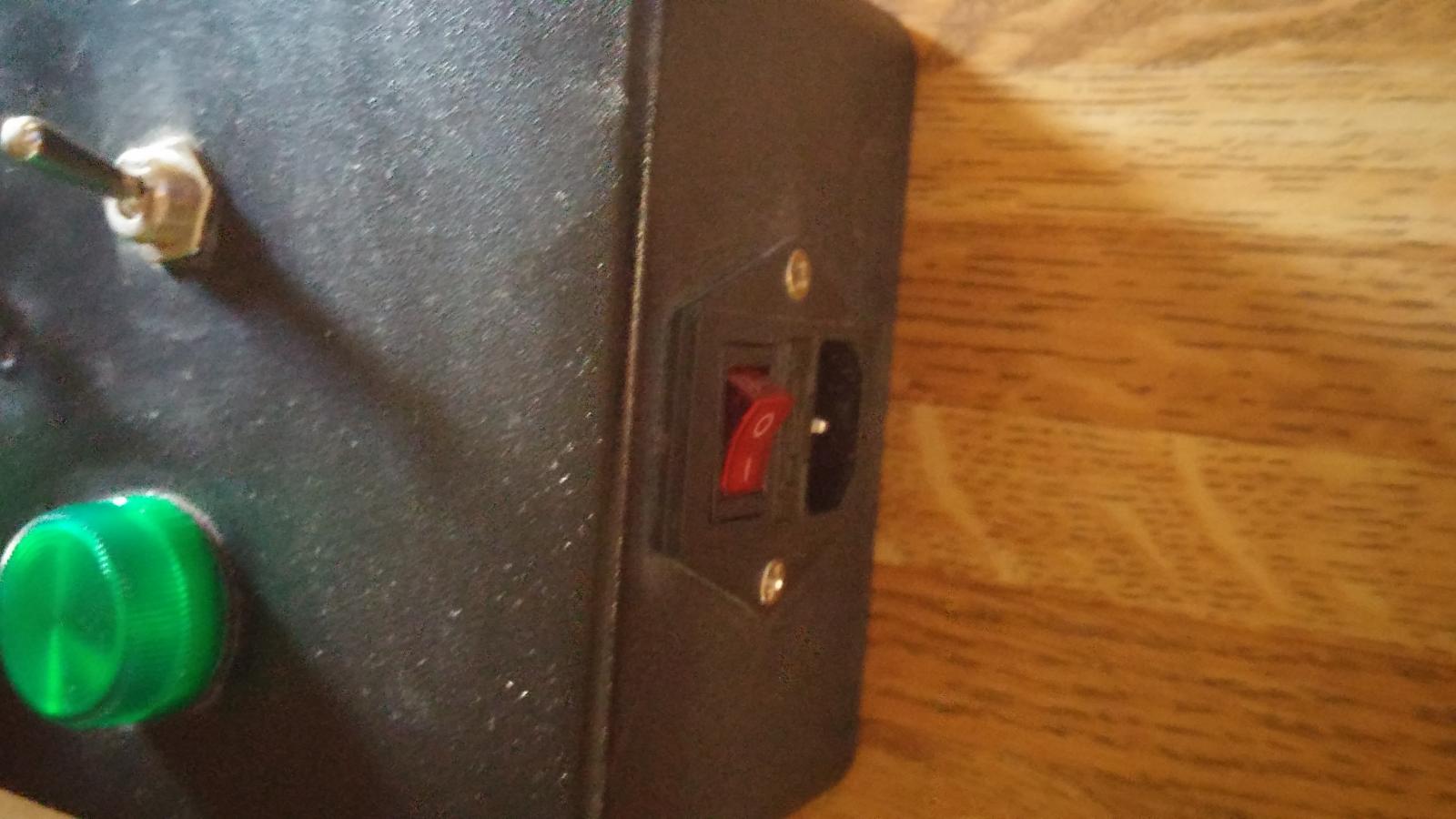
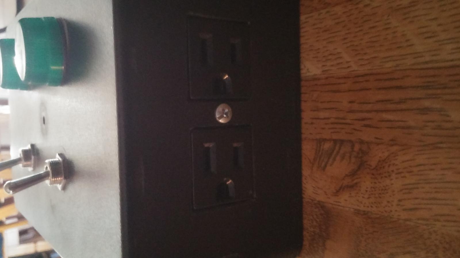
Nice build. I built something like this for a pump cart with two chuggers but with an outlet as opposed to direct wired. I used a two switch component (two switches in the footprint of an outlet) and an outlet in a two gang box. You can make the outlet so that each half is switched independent of the other while sharing power. I wired to an extension cord.

KIMG0004.jpg


KIMG0005.jpg
 
This is perfect! Thank you very much...I figured it could be done but lacked any real knowledge around this area. Thanks again!
 
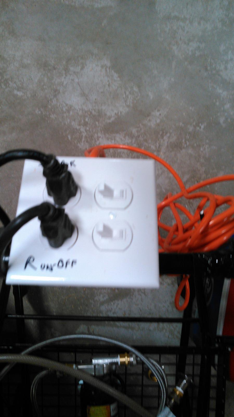
My final product. Thanks for the help!

p.s. motors have protective covers.

IMG_9271.JPG.jpg
 
Last edited:
This is exactly what I was looking for but I have a question. I don't want to cut the plugs off my pumps instead would rather be able to plug in and unplug. I was thinking of building a junction box at the bottom of the stand with some GFCI plugs providing power with a long extension cord.

Then wiring up a control box with a two gang switch box similar to the OP. My question is....would it be smarter to put the GFCI at the pump plugin or further down stream such as the the plug for the extension cord. I wasn't sure if two "half-hot" GFCIs are ideal since I would really only need two outlets and half hot GFCIs would provide four.

Any suggestions/ideas are welcome. I am far from an electrician and am trying not to kill myself or set something on fire. ha. Cheers!

You want that gfci downstream. If you don't have a gfci plug where you're brewing, get a gfci extension cord.
 
Hi! Thanks so much for posting this. I have a clarification question about the two black wires from the chugger pumps. It looks from the diagram that those two wires should be joined together with a wire nut/splice connector. However, it appears from the picture that they are not connected. And also, the wording in the instructions could be read both ways.

Could you please clarify?

Thanks!
 
So there is one black wire (power) coming from the extension cord. This needs to be split to the 2 switches. Then the black of each pump wire goes to the other side of each switch. The only blacks you're joining together is to split the 1 black extension cord wire to provide power to 2 switches. I hope that makes sense.
 
So there is one black wire (power) coming from the extension cord. This needs to be split to the 2 switches. Then the black of each pump wire goes to the other side of each switch. The only blacks you're joining together is to split the 1 black extension cord wire to provide power to 2 switches. I hope that makes sense.

Got it!!! Thanks so much for clarifying.
 

Latest posts

Back
Top