• Please visit and share your knowledge at our sister communities:
  • If you have not, please join our official Homebrewing Facebook Group!

    Homebrewing Facebook Group

DIY Brewing Controller

Homebrew Talk

Help Support Homebrew Talk:

This site may earn a commission from merchant affiliate links, including eBay, Amazon, and others.

smadaus

Well-Known Member
Joined
Aug 10, 2015
Messages
65
Reaction score
3
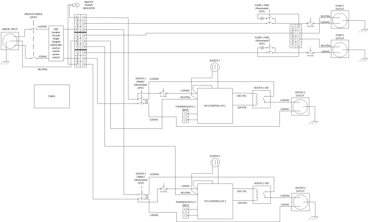
My friend and I are building a brewing controller and we figured we post the electrical layout on here to see what people think. If anyone has suggestions on what we might be missing or maybe an issue you see, feel free to let me know. Also we are still looking around for a housing for the controller, if anyone has any suggestions on that too.

I am mainly going to use this to control a rims system with the option to control a HLT heater in the future. Both will be 240V while the 2 pumps I have are 120V. I will be plugging this into my range outlet which is (2) 40a circuits.

Decided to go with the lighted button combo, green and red.
http://www.digikey.com/product-detail/en/cherry/WRG32F2FBGLN/CH791-ND/446057

Took me a little to find a PID that came in F, but I found this one.
http://www.thermomart.com/mini-controller


I was trying to save some money by making it myself so some of the items I was really searching for the lowest priced decent quality items. Like I said I am open to suggestions on any of this stuff. Thanks guys.
Brew Rig 4 (2).jpg
 
I would look at auber instruments for your PiD, they are a little more, prob made by the same people that made the one you linked, but 1000s on here use them and there is a ton of info related to them
 
I recommend that you go with water tight switches (NEMA 4 rated) since they will be used near water.
 
I would recommend the mypin model TD4 which has manual pwm mode for a better controlled rolling boil and half the price of the auberins unit.
 
Thanks guys, I will probably check out the Auberin PIDs, I would imagine they might offer more customer support as well. I will also definitely be looking into the NEMA 4 rated buttons, I should have thought of that before. Switches were labeled wrong, thanks for pointing that out.
 
Thanks guys, I will probably check out the Auberin PIDs, I would imagine they might offer more customer support as well. I will also definitely be looking into the NEMA 4 rated buttons, I should have thought of that before. Switches were labeled wrong, thanks for pointing that out.

How many watts are your elements, and do you intend to fire both at once, or only one at a time? If only one at a time, you should have some kind of positive interlock to prevent you from turning both on at once. A two pole, three position (center off) high current rotary selector switch is good for this.

The original PID's you linked are not suitable for controlling SSR's driving heating elements. Those PID's have relay outputs, and you need fast switching which will drastically shorten the life of the relays. Also, a relay will not drive an SSR without a auxiliary power supply. MyPin TD4-SNR PID's are suitable and widely used, as are the Auber PID's.

You don't show GFCI protection on the power feed to the panel. Do you have that available? Don't ever use electricity in a wet area with out GFCI protection.

Breaker 1 and Breaker 2 need to be a single ganged 2 pole breaker.

What are you using as a master power switch (which needs to be DPST not SPDT)? Also, needs to be rated for 40A @ 240V.

You should use DPST switches to provide disconnects for both hot lines feeding each element. Switching the PID signal to the SSR will only shut off power to one hot leg of the element, so the element will still have 120V on it from the other hot leg. Also, SSR's most often fail to the closed (on) condition, and in case of a failure you can't shut the element off except by killing the main power.

You don't need to run neutrals to the element plugs. You can save some money by using 3 conductor wire vs. 4 conductor.

You don't need to switch the neutrals for the pump indicator lights, so you can use SPST switches for the pumps.

You should fuse the pump hot lines, especially if you intend to wire with less than 8AWG wire.

You should fuse the hot lines to the PID's (one 1A fuse can handle both), and use finer wire to connect them (anything from 20AWG to 16AWG.)

That's all I could come up with for now.

Brew on :mug:
 
How many watts are your elements, and do you intend to fire both at once, or only one at a time? If only one at a time, you should have some kind of positive interlock to prevent you from turning both on at once. A two pole, three position (center off) high current rotary selector switch is good for this.
Brew on :mug:

I only copied the first paragraph of your quote so that the post wasn't twice as long. I am still figuring the message board out so I wasn't sure if I could quote multiple things in different parts of the post. Either way I asked my buddy who is the electrical engineer behind this whole thing and he gave me some responses. Let me know what you think and also we really appreciate your input, thanks for an awesome review.


How many watts are your elements, and do you intend to fire both at once, or only one at a time? If only one at a time, you should have some kind of positive interlock to prevent you from turning both on at once. A two pole, three position (center off) high current rotary selector switch is good for this.

Each heater is 14.6 A, 3500 W. We should be good for both at the same time but we can make it so that you can only turn one on if you want.


MyPin TD4-SNR PID's are suitable and widely used, as are the Auber PID's.

Is this the one you were talking about? Also would you recommend this one or one from Auber?
https://www.amazon.com/Programmable-Thermostat-Temperature-Controller-Comsumption/dp/B00X6SEWS4/ref=sr_1_1?ie=UTF8&qid=1469749725&sr=8-1&keywords=TD4-SNR+PID


You don't show GFCI protection on the power feed to the panel. Do you have that available? Don't ever use electricity in a wet area with out GFCI protection.

They are GFCI, diagram will be updated.


Breaker 1 and Breaker 2 need to be a single ganged 2 pole breaker.

It is and will be drawn better in the new diagram.
https://www.amazon.com/Siemens-Q240-240-Volt-Circuit-Breaker/dp/B00002N5HK/ref=sr_1_6?s=industrial&ie=UTF8&qid=1469405006&sr=1-6&keywords=40a+breaker
'


What are you using as a master power switch (which needs to be DPST not SPDT)? Also, needs to be rated for 40A @ 240V.

Having trouble finding one, any suggestions?


You should use DPST switches to provide disconnects for both hot lines feeding each element. Switching the PID signal to the SSR will only shut off power to one hot leg of the element, so the element will still have 120V on it from the other hot leg. Also, SSR's most often fail to the closed (on) condition, and in case of a failure you can't shut the element off except by killing the main power.

Didn’t know SSR’s would fail to closed. Probably have to go back to cutting power directly to the heater and not going through the SSR control. We will cut it to both hot phases.


You don't need to run neutrals to the element plugs. You can save some money by using 3 conductor wire vs. 4 conductor.

Yea wasn’t sure if it needed the neutral… Sounds like it won’t though so I’ll remove it


You don't need to switch the neutrals for the pump indicator lights, so you can use SPST switches for the pumps.

Not sure what you mean?


You should fuse the pump hot lines, especially if you intend to wire with less than 8AWG wire.

Will do.


You should fuse the hot lines to the PID's (one 1A fuse can handle both), and use finer wire to connect them (anything from 20AWG to 16AWG.)

Will do.


Also I will upload the next diagram sometime next week probably. Take a look at it and tell us what you think. Thanks again.
 
Last edited by a moderator:
Each heater is 14.6 A, 3500 W. We should be good for both at the same time but we can make it so that you can only turn one on if you want.


Breaker 1 and Breaker 2 need to be a single ganged 2 pole breaker.

It is and will be drawn better in the new diagram.
https://www.amazon.com/Siemens-Q240-240-Volt-Circuit-Breaker/dp/B00002N5HK/ref=sr_1_6?s=industrial&ie=UTF8&qid=1469405006&sr=1-6&keywords=40a+breaker
'


What are you using as a master power switch (which needs to be DPST not SPDT)? Also, needs to be rated for 40A @ 240V.

Having trouble finding one, any suggestions?

Have you thought about using something like one of these?

http://www.auberins.com/index.php?main_page=product_info&cPath=7_32&products_id=580

http://www.auberins.com/index.php?main_page=product_info&cPath=7_32&products_id=586

Unfortunately Auber doesn't offer a 40A unit, but if you opt to select between elements, couldn't you go with a 25A master switch/breaker? Or, what if you split the internal wiring into two separate PID/element/pump circuits and use two independent 20A master switch/breakers?
 
Last edited by a moderator:
I only copied the first paragraph of your quote so that the post wasn't twice as long. I am still figuring the message board out so I wasn't sure if I could quote multiple things in different parts of the post. Either way I asked my buddy who is the electrical engineer behind this whole thing and he gave me some responses. Let me know what you think and also we really appreciate your input, thanks for an awesome review.

How many watts are your elements, and do you intend to fire both at once, or only one at a time? If only one at a time, you should have some kind of positive interlock to prevent you from turning both on at once. A two pole, three position (center off) high current rotary selector switch is good for this.

Each heater is 14.6 A, 3500 W. We should be good for both at the same time but we can make it so that you can only turn one on if you want.

With a 40A feed, you don't need to have a "one heater only" interlock, since the total possible load will be well under 40A. Would be different if you were using 5500W elements.

MyPin TD4-SNR PID's are suitable and widely used, as are the Auber PID's.

Is this the one you were talking about? Also would you recommend this one or one from Auber?
https://www.amazon.com/Programmable-Thermostat-Temperature-Controller-Comsumption/dp/B00X6SEWS4/ref=sr_1_1?ie=UTF8&qid=1469749725&sr=8-1&keywords=TD4-SNR+PID


That is the appropriate MyPin PID, and many brewers use and like these. You could also use Auber SYL-2352's or Auber SYL-2362's. My preference for controllers are the Auber DSPR120 or DSPR300. These controllers perform similar functions to the PID controllers, but use (a non-PID) algorithm that seems to be more stable and easier to tune than PID's for brewing applications. The MyPin is the least costly of the preceding options.

...

Breaker 1 and Breaker 2 need to be a single ganged 2 pole breaker.

It is and will be drawn better in the new diagram.
https://www.amazon.com/Siemens-Q240-240-Volt-Circuit-Breaker/dp/B00002N5HK/ref=sr_1_6?s=industrial&ie=UTF8&qid=1469405006&sr=1-6&keywords=40a+breaker
'

What are you using as a master power switch (which needs to be DPST not SPDT)? Also, needs to be rated for 40A @ 240V.

Having trouble finding one, any suggestions?

You can use these as both a switch and a breaker: http://www.auberins.com/index.php?main_page=product_info&cPath=7_32&products_id=586

...

You don't need to switch the neutrals for the pump indicator lights, so you can use SPST switches for the pumps.

Not sure what you mean?

In the part of the circuit shown below, one pole of of the DPST is switching the neutral line to the pump indicator lamp (but not the neutral to the pump itself.) There is no need to switch the neutral.

Switching Neutral.jpg

...
See answers in red above.

Brew on :mug:
 
Last edited by a moderator:
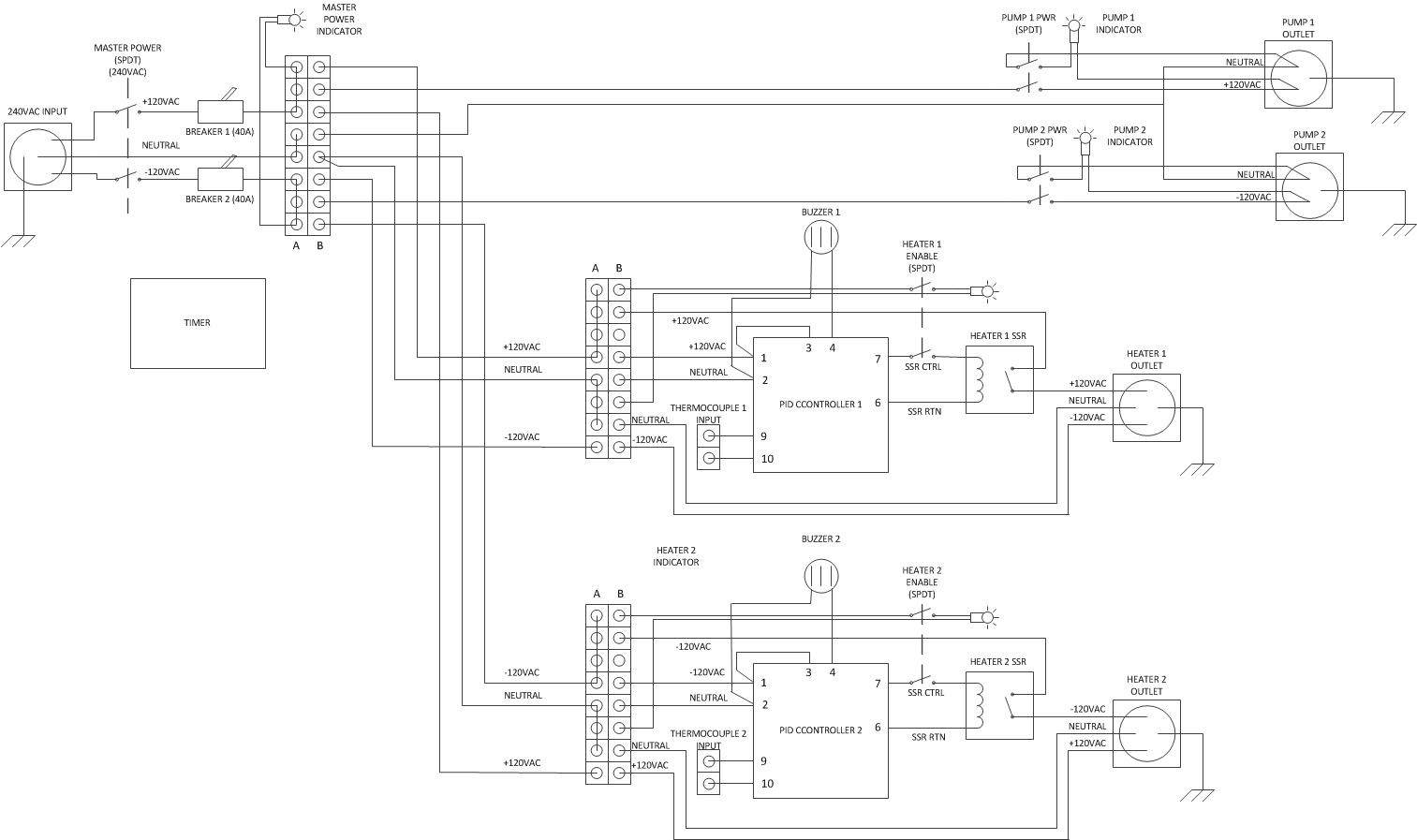
Sorry for posting so late, super busy this past week and couldn't find time to get on. Anyway here is the next diagram, please take a look and let me know what you think. Thanks guys.

Brew Rig 5.jpg
 
Back
Top