• Please visit and share your knowledge at our sister communities:
  • If you have not, please join our official Homebrewing Facebook Group!

    Homebrewing Facebook Group

CraftBeerPi - Raspberry Pi Software

Homebrew Talk

Help Support Homebrew Talk:

This site may earn a commission from merchant affiliate links, including eBay, Amazon, and others.
Don't know yet. As soon as I have the boards finalized and submitted to the company I'll let you know. Should be in the next few days. I'll collect money when I have boards in hand.
 
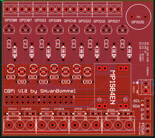
boards are done.

Screen Shot 2016-09-29 at 6.47.26 PM.png
 
It depends on which footprint you use, that's why it's marked with a "1". As far as streams being crossed. There aren't any except for power being distributed to each pad. Now, the way I have the board setup is that you can pick to use any of the pins as 1 wire, you just have to jumper the 3v for parasitic power.
 
ds18b20 parasitic power mode is a crap paradigm, and frankly an implausible application when you actually have a three terminal connector for the probe.

So, does the software support non-parasitic power mode?

Cheers!
 
So are you saying you don't need to jump data and 3v?

The 1-wire bus needs a pull-up on the data line for normal mode or parasitic mode, so your jumper is not necessary. What is its intended function?

Parasitic mode can be configured on the 1-wire device (not at the driver PCB). Either purchase a parasitic version of the device, or connect the device's power and ground pin together.

Some devices are only available as parasitic-powered devices. They have no power pin, just data and ground.
 
The jumper is used in case you are using that pin as a 1wire for ds-18b20 or as a regular gpio. :)
 
Also, I've had a few beers so if that doesn't make sense right now, I'll wait for your design and re-read my posts and correct accordingly.
 
No, it makes sense. If there were no jumper pads you could just omit the resistor when you assembled the board.

Most people use a single pin to drive the 1-wire bus and connect all of their sensors to it.
 
Right, it's a matter of providing a board that's versatile enough to fit everyone's needs and allowing customization.
 
R11, r12, r13, r14. Yes. Let me get the boards in and I'll do a video/documentation. Ame makes a great point that I didn't express. Not ALL of the pins/parts of the pcb need to ne populated. All will be completely clear when I send boards.
 
Can you post a schematic? That might make a few things clearer.
 
Understood, I plan to initially populate only 3 12V (1 PWM + 2 hi/low) and 1 1-wire outputs. However, I still really like your jumper feature for anyone wanting to fully populate the board on initial build and then be able to reconfigure GPIOs 15, 18, 23 & 24 anytime later as desired.
 
Yes. As soon as I get home from drinking beers, I'll screen grab the circuits.io schematic.
 
Ame, I want to make sure I address the right questions so; I'm glad to answer but also want to understand further concerns.
 
R11, r12, r13, r14. Yes. Let me get the boards in and I'll do a video/documentation. Ame makes a great point that I didn't express. Not ALL of the pins/parts of the pcb need to ne populated. All will be completely clear when I send boards.

Video and documentation is awesome, thanks for that. I'm a noob to this :) so appriciate it.
 
I guess I should ask, is anyone interested in built and tested boards or component kits? I have tons of pieces parts etc. and can put together pricing.
 

Latest posts

Back
Top