• Please visit and share your knowledge at our sister communities:
  • If you have not, please join our official Homebrewing Facebook Group!

    Homebrewing Facebook Group

Can someone check my Diagram?

Homebrew Talk

Help Support Homebrew Talk:

This site may earn a commission from merchant affiliate links, including eBay, Amazon, and others.
I was willing to risk burning up a SSR to see if this would work. I used it a few times, but quickly progressed to a BCS controlled system.

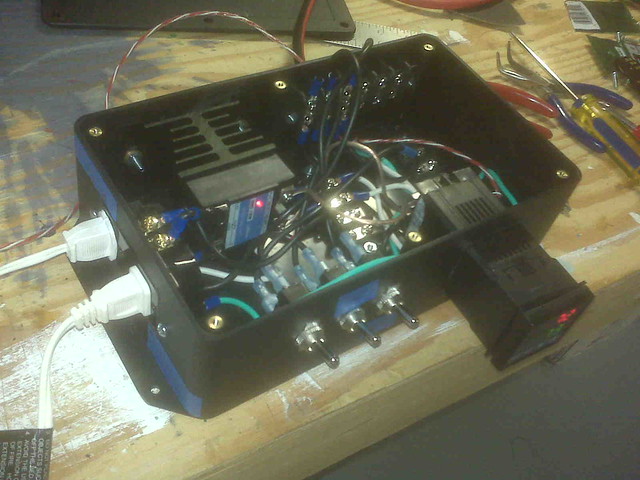
I put a thermometer in the box and sealed it as best I could. Under 50% duty cycle running a 1680watt heatgun and a pump for 3 hours, the temp never exceeded 100f which is 37.8c. The operating range of the auber ssr is up to 70c.

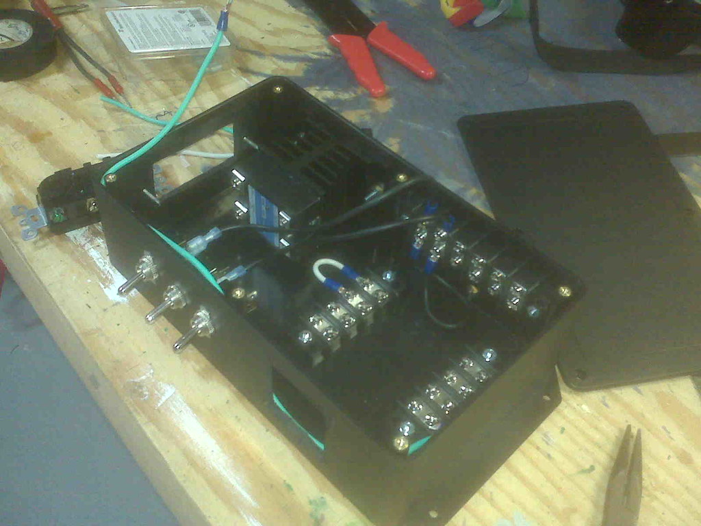
There are NO fuses or over current protection in this build and the wiring is a rats nest.

I had no problems with it in probably 6-8 brews that it was used in. I still use the "Digital Thermometer" portion on occasion.

Ed, excellent observation. That is a very tight fit for the heat sink in that box, and it still did not heat up much. Thanks for sharing.
 
Well the heatsink pictured is not going to work, I'm going to order one of the Auber units and just drill it in even though I don't want to. I wanted to mount this case on a shelf and a screw head out the bottom will mess that up but oh well. Also there is no such thing as a high temp glue that bonds plastic and metal.
 
eh, wasn't meant to be. Auberins heatsink en route. Will get the terminal buses mounted today though, maybe some wiring.

Should I start a new build thread or does someone wanna change the thread title for me?>
 
Ok so I got the heatsink for the SSR. I mounted the rest of the terminal buses and the ssr. But I think I screwed up. In my head I assumed I could use a regular home outlet to control 2 separate devices independently. But I'm looking at the thing and despite being two set of terminals for hot an neutral they are bridged.

I wanted to be able to turn the pump and element on independently but it seems like that's not going to happen. I'm unsure what to do besides just plugging the pump into the wall and switching it manually when needed...

Thoughts? Why are there two of each terminal on these things? Maybe if you want to run power to the next one down the line on the wall?
 
There are little tabs of metal that bridge the two outlets together on the side. You can break these off (work it back and forth with pliers until it detaches). This separates the outlets.

You only need to do this on the hot side and then use both screws, one for element and one for pump. The neutral side can be left bridged with only one wire connected to it.
 
That is *specifically* what those tabs of metal are meant for and the reason there are two sets of screws, so yes... It's advisable. :)
 
Thanks Walker, upon further review I feel comfortable doing that :). I'm taking a quick beer and HBT break from wiring. So far I have 2 questions. On the switches is it safe to assume that of the 2 terminals available the one on the off side is the in terminal and the one near the on side is the out terminal? And same for the SSR. 1 & 2 are the 120V terminals, is 1 in and 2 out?

5547754855_7ef5fc1220_b.jpg
 
There really is no "in" or "out" with the switches and AC load side of the SSR. It doesn't matter how you connect the wires.

The one pair of connections that DO matter is the DC control signal from the PID to the SSR. That one needs to be hooked up properly with the "+" and "-" terminals.
 
Yea I saw the DC indications. The no in or out is blowing my mind a little bit but I think I got ya. I'm excited to test this thing out with a light bulb, hopefully I can power through it later.
 
a switch (or an SSR, which is really just a switch) simply connects two pieces of metal together. No concept of IN or OUT. Just "CONNECT THESE TOGETHER".

Now, if you had selector switches or other fancy things, then you would have to put thought into which wire connected to which pin, but for a simple ON/OFF switch.... doesn't matter.
 
Gotcha. Now for the SSR, I couldn't find spade terminal ends small enough to fit on the SSR and fit my wire. Can I just wrap the wire around the nuts? And is it ok to use 14g wire for the DC lines?
 
Is your wire stranded copper or solid copper?

The wire is fine to use for the DC. It's a hell of a lot bigger than necessary, but you and use it.

I used some old thin speaker wire for my DC stuff.
 
It's Alive. Thanks so much for your help guys. I'll chronicle the whole build in another thread.
5554718206_f5fd651408_z.jpg
 
Thanks! So, I'd like to autotune the thing tonight. But I have not potted the element nor have I had a grouding screw welded to the rims tube yet. Am I asking for trouble if I run it with the terminals exposed and the ground wire taped to the rims tube?
 
Thanks! So, I'd like to autotune the thing tonight. But I have not potted the element nor have I had a grouding screw welded to the rims tube yet. Am I asking for trouble if I run it with the terminals exposed and the ground wire taped to the rims tube?

I always try to err on the side of caution with these kinds of things, so I cannot recommend you doing this.

If you decide to do it anyway, I would suggest not ever ever ever touching the RIMS tube.
 
Just wanted to follow up, this has been working great, although I still haven't found a permanent grounding solution for the RIMS tube. I ended up sealing the connection for hot and neutral to the element with liquid electrical tape and so far that has been great.
 
Back
Top