BruControl: Brewery control & automation software

Homebrew Talk - Beer, Wine, Mead, & Cider Brewing Discussion Forum

Help Support Homebrew Talk - Beer, Wine, Mead, & Cider Brewing Discussion Forum:

This site may earn a commission from merchant affiliate links, including eBay, Amazon, and others.
it took many hours, but dug up my old CBPi3 boards and wiring harnesses and used them to get the hardware addresses... and printed them on some wraps to put on the probe leads... BruControl NEEDS this functionality....
1666213506600.png
 
it took many hours, but dug up my old CBPi3 boards and wiring harnesses and used them to get the hardware addresses... and printed them on some wraps to put on the probe leads... BruControl NEEDS this functionality.... View attachment 784164
We can add a control code to show you the addresses of the indexed sensors. Not sure that helps you right now but it’s easy enough.
 
Do you have any normal ESP32 Dev boards you can test side by side?
I have two normal ones that sit on top of my fermenters for Tilt readings. They have occasional drops but always reconnect. I haven't had one completely drop and not come back online. They don't control anything, just take Bluetooth readings.

My keezer uses a Lilygo ESP32 relay module and same. Comes back online if the connection drops for a second. It only monitors the temps and turns on the keezer.

The two problematic ones are the RobotDyn relay boards, which monitor temp and pressure and control a pump, heat wrap, and spunding solenoid each. That's why I thought the complete drop (and seeming lockup) was an electrical feedback issue, since it has these devices connected.
 
I think that would be a great addition. I suggest hardware address, offset, and a readable value of temp(uncalibrated is OK)...

Just need to keep in mind we're dealing with a microcontroller which has limited memory. If we abandon the MEGA today (in favor of ESP32, M0/M4 based cards, etc.), this gets a lot easier as they have much more memory. But I have a feeling that would piss off some people!
 
point taken... and I have not made the recent jump to the latest FW/SW anyway.. I will put a couple ESP32 unishields in the equipment budget to be prepared.

Might be a good time to announce an upcoming 'final edition' firmware for our beloved 256k mega. It can join my BCS462 on the shelf... I assume that ESP8266 would also forced into retirement but ESP8285(1MB) used in the sonoff dual R2 would be OK?
 
I know this has probably been covered a few times, but I need to ask: I just received my Unishield, and I intend to power it with my Meanwell 24 VDC 4 A pwr supply. Plan is to bring 24 VDC on pin VS, adjust the DC-DC converter's voltage to 5.0 then move Unishield pwr switch from VR only to VR- 5V.

Per the Unishield product note, the max input current = 3A. Can I proceed with my 4A pwr supply without damaging anything?
 
Just need to keep in mind we're dealing with a microcontroller which has limited memory. If we abandon the MEGA today (in favor of ESP32, M0/M4 based cards, etc.), this gets a lot easier as they have much more memory. But I have a feeling that would piss off some people!

Rip off the bandaid! Arm for the win. M4 can rip.
 
I would say provide a recommended path forward along with a guide for making the change away from MEGA, then set a date \ version change that would not longer support MEGA. Obviously if they do not update to that version then the MEGA continues to work.

I am currently on MEGA, as long as there is a good notification and a little help guide on making the change I personally would not have an issue with it. I do not know if there would be any major issues or changes that would need to be made with items like the RTD Amplifier board you offer, running analog flow meters, or controlling multiple electronic ball valves. I am going to assume there would not be, lol.
 
Part of the concern of abandoning the MEGA is there is really only one drop-in upgrade: The Adafruit Grand Central M4. I'm not sure how long they will offer/support it. It's also nearly 4x the price. So it could be a transition opportunity, for those who need that form factor. BUT, longer term, I'd like to abandon that form factor because it is fairly inefficient. It's also kinda a PITA that the connection pins are female and on top of the board. This makes integration a bit tricky (hence the UniShield's underslung type design).

Anyway, random musings... the MEGA isn't EoL for a while!

Edit: Actually the Due is a replacement too. We have support for it but haven't tested it in a while - would just need to do that.
 
I'm finally getting around to upgrading to 46D firmware. I previously had the 45O firmware running with the 7/31 updated BruControl and had fixed all my analog port #'s. With the 45O firmware, everything was 100% reliable.

After upgrading the MEGA2560 to 46D, none of my digital outputs seem reliable. A random number of the 24 relays I have DO ports connected to power on at startup, even though the BruControl device shows the state as being off. I usually have to click on each one twice to get it to synchronize back to the off state. Sometimes adjusting one DO, causes another DO to kick on. As I was typing this post, a valve just decided to change state. Very weird.

Any ideas?
 
Did you check the updated Interface Wiring Maps? The numbering system changed a bit, and you’ll need to use the new interface definitions in the BruControl application.
I updated the Wiring Map selection on the interface in BruControl to "Ethernet_FW_v46" - should that be "Default" since the Interface Wiring Map for v46 shows "Default" below?
1666560570345-png.784493


I also adjusted all the Analog ports to the new numbering. I compared my Ethernet wiring map from Feb to the current v46 one and there are a few changes outside of the analog ports but nothing that affects my wiring.
 

Attachments

  • 1666560570345.png
    1666560570345.png
    55.2 KB · Views: 394
Also did you download the latest BC application? It will be the same version but has the Interface Definition files which matches the Interface Wiring Map.

You will want to use "Ethernet_FW_v46". Now, when you switch to this map, your existing elements will get erased, so we need to fool it by editing your configuration file. You can do that by closing BC, making a backup copy of your configuration file, then opening the configuration file with a text editor, and changing your interface's declared wiring map from Default to Ethernet_FW_v46. This will be in the between tags Wiring map, for example: WiringMap>Ethernet_FW_v46</WiringMap>

If that's not making sense, please feel free to email us your configuration file (it's in your Documents/BruControl file, with the name matching your selected configuration name, with the .brucfg extension.

Should v46 not work for you, you can drop down to 45Q, which uses the new map but with the old firmware code.
 
I updated the Wiring Map selection on the interface in BruControl to "Ethernet_FW_v46" - should that be "Default" since the Interface Wiring Map for v46 shows "Default" below?
1666560570345-png.784493


I also adjusted all the Analog ports to the new numbering. I compared my Ethernet wiring map from Feb to the current v46 one and there are a few changes outside of the analog ports but nothing that affects my wiring.
Hi Don. Trying to duplicate this... are you still having the problem with firmware v46D?
 
Hi Don. Trying to duplicate this... are you still having the problem with firmware v46D?
That's a coincidence. I was just going to start up the panel to continue testing. As of last week I was still having the problem.

Here's my config changes:

Sometime in early September I upgraded to BruControl 7/31/2022 release. At the same time I upgrade to firmware 45O. Everything seemed to be working. I edited my my config file to set the Wiring Map to "Ethernet_FW_v46" and renumbered the analog devices. All analog devices and digital outputs worked correctly during a test.

A couple of weeks ago, I upgrade firmware to 46D. I also downloaded BruControl again and updated it. Ever since this point, I have unreliable digital outputs. On startup, I have a script that closes all valves and I can hear valves moving. What's happening is some portion of the ports are opening but the BruControl devices show them as closed State = Off. If I click on one the devices, BruControl shows State = On without any noise from the valve (so I know it's open already). If I click again, the valve can be heard to close and the BruControl shows State = Off. Sometimes another digital output will trigger State = On but this NEVER happened before in six months of prior use.

I was going to test this one more time in an hour. Let me know if you'd like to participate.
 
OK thanks. With the "Ethernet_FW_v46" interface map used, you should use 45Q without any issues.

For 46D, I am hearing your experience is not isolated. I tried to duplicate it on the bench but could not. So my ask is that we recreate the problem, then start disabling other devices up to the point the problem goes away, if at all. If we can't duplicate it, we cant figure out how to fix it as you know.
Oops, I meant 45Q in my previous post.

I can say the specific digital ports that act up is random.

Is there any difference in the firmware initialization of 46D from 45Q? It really seems like the MEGA is (randomly) misreading port statuses on startup with 46D.

I'll test 46D while I'm still on it. I can record which ports act up on startup. I can do this 2-3 times to see if it's really random or if there's a pattern I haven't noticed yet.

Afterwards, I'm going back to 45Q first to make sure things are still working on that version.
 
We changed the internal active port database to improve memory. 45Q uses the prior database with the new map, whereas 46 uses the new database with the new map.

Hate to hear "random"... that and microcontrollers don't go hand-in-hand, lol.
 
Long road but I am finally wiring my brewery. I have my stand built and in place and wire chases made for my various wires. I am running all the 110/220m vac in their own chase. I am running all my valve wire ( 12 vdc control wires) in their own chase. I will also run some of my 10 K NTC probes along with the valve wiring (but I do not have to). I also have two 4-20 ma flow meters (SM6004) that have 4 wires. I may need to make an extension for those wires and would solder splice to those leads. I plan to run them with the valve wires. Any time the valve wire bundles cross the AC, they are at 90 degrees.

My general questions:

1. Am I correct in running the 4-20 ma along with the 12 vdc valve control wires?
2. Am I correct in running the 10 K NTC probe wire along with the 12 vdc valve control wires?
3. Can I simply splice the 4-20 ma wires?
 
1) 4-20 is more robust since EMI via voltage induction does not affect current measurement the same way, so you should be fine.
2) Yes it will be fine.
3) Yes you can splice them, it's done routinely in industry when loop powering devices so no worries there either.

Cheers,
Joe
 
Thanks for the quick response. I will start running the wires this afternoon. I have 20 valves (12 or 24 vdc control along with independent 12 vdc for LEDs), 5 pumps, 2 ignitors, 10 temp probes, 2 gas valves (12 vdc). 2 flow meter (4-20 ma) 4 heating elements and one pressure volume sensor all requiring wiring. Some of the wiring is already installed or will be above my vessels ( some of the temp probes) I have 5 hot side vessels and all have tippy stands ( mash tun and two brew kettles are bottom drain as well). I had a BCS brewery before, but BruControl has allowed me much more control and automation!
 
Just posted v46F... this version fixes an issue where digital outputs were erroneously turning on across incorrect ports. 46F also reports 1-wire device addresses over debug during bus resets, per @clearwaterbrewer's request.

For MEGA and GC interfaces, remember not to update to 45Q or 46F without changing your wiring maps in BC. This requires manually editing your configuration file if you do not want to erase all your configured devices on that interface. Instructions above.
 
Yes, we have the FW working. Might need some testing on all the pins, but we can publish a beta version for anyone willing to take the plunge.

I think this will be the micro to beat! Given the I/O and other features, it will have a lot of runway for the future.
 
Yes, we have the FW working. Might need some testing on all the pins, but we can publish a beta version for anyone willing to take the plunge.

I think this will be the micro to beat! Given the I/O and other features, it will have a lot of runway for the future.
I would take the plunge!
 
I have a bunch of cheap PT100s and some of them arrive DOA or simply stop working after being in service. Rather than buying new housing, stem etc can I just replace the sensor itself (resistor?). Does anyone know a link to a part that might fit here?

The ceramic insulators are around 3/16" OD and the sensor itself around 1/8" OD. Total wire length needs to be around 10" to hook back up to terminals
 

Attachments

  • IMG_20221115_174110073.jpg
    IMG_20221115_174110073.jpg
    1.5 MB · Views: 0
  • IMG_20221115_174059613.jpg
    IMG_20221115_174059613.jpg
    2.1 MB · Views: 0
I have a bunch of cheap PT100s and some of them arrive DOA or simply stop working after being in service. Rather than buying new housing, stem etc can I just replace the sensor itself (resistor?). Does anyone know a link to a part that might fit here?

The ceramic insulators are around 3/16" OD and the sensor itself around 1/8" OD. Total wire length needs to be around 10" to hook back up to terminals
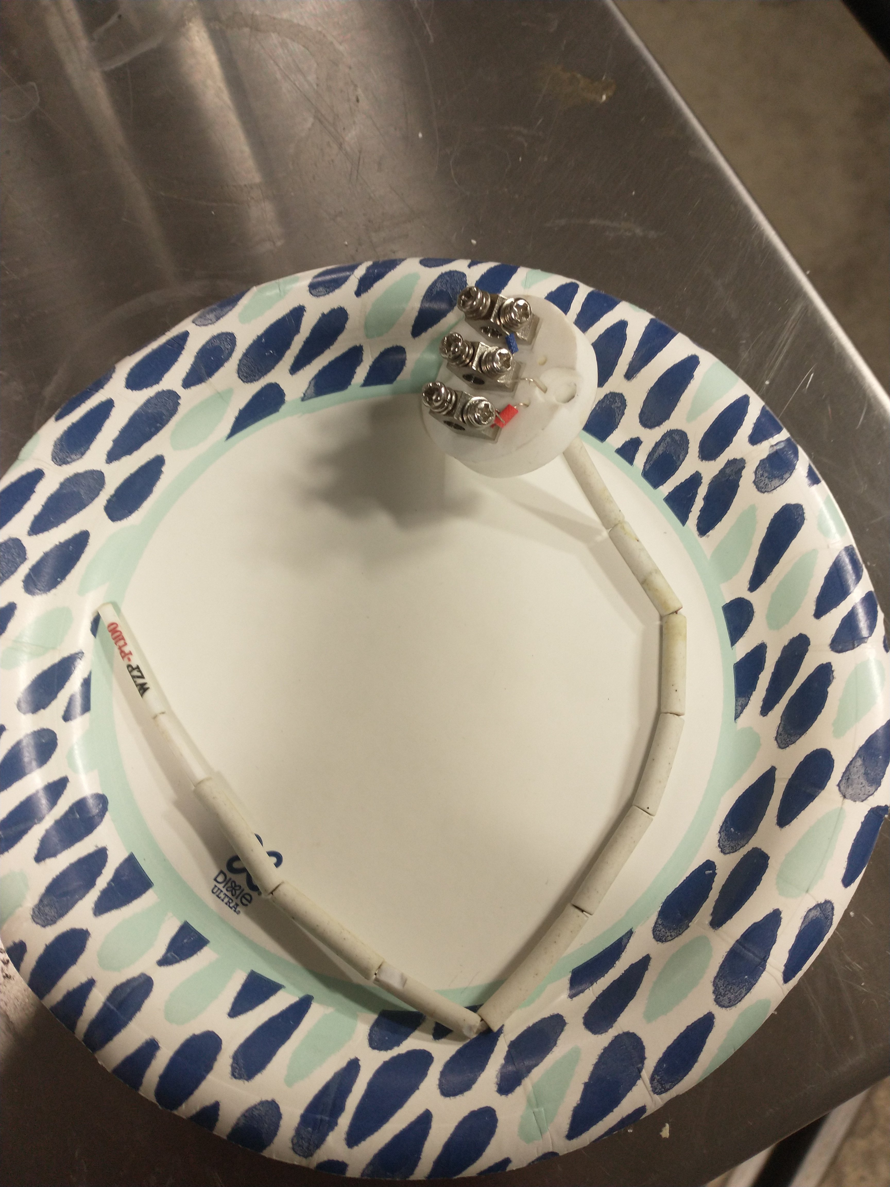
Yes, you should be able to replace the sensor, assuming that is truly what is failing. You should test the leads with a meter to verify. Same color wires should be ~1 ohms or less and different color wires should be ~100 ohms. Nothing should be low impedance to ground.
 
FYI:

I do not need any help as I solved my issue.

I upgraded my Grand Central to 46F which did fix a problem with UNI Digital Outs being on when no called for, but it also changed the Network Setting on the board.


I had the following settings prior to upgrade:

MAC:6E:7B:81:59:B2:93
IP:192.168.0.160
GW:192.168.0.1
SN:255.255.255.0

After I upgraded the Firmware I had:
I had the following settings:

MAC:------------------
IP: 255.255.255.0
GW: 255.255.255.0
SN: 255.255.255.0

I redid the setup and it is fine .


MAC:6E:7B:81:59:B2:93
IP:192.168.0.160
GW:192.168.0.1
SN:255.255.255.0
 
We can add a control code to show you the addresses of the indexed sensors. Not sure that helps you right now but it’s easy enough.
I had my latest batch of 1-wire probe assemblies (1 probe per meter with 5m lead, 9m total length) made with the individual probe addresses enumerated, being able to statically assign 1-wire addresses would be really nice!
1668952599390.png
1668952599390.png
 
Unishield Question : input to the unishield is 24vdc, output of onboard converter is set at 5.0vdc. I would like to power VA or VB with 5 vdc from pin VCC or VR.
- what is the max amp draw from VR or VCC?
 
…or would it be safer to use a dedicated 5VDC supply? In my scenario, I intend to use 4 analog outputs via D pins to the analog amp for my proportional SSR’s.
 
Unishield Question : input to the unishield is 24vdc, output of onboard converter is set at 5.0vdc. I would like to power VA or VB with 5 vdc from pin VCC or VR.
- what is the max amp draw from VR or VCC?
If powering an analog amp for PWM, would you not use the P Pins? For a Mega, they have the 5 vdc max you are looking for. I am not sure you can even use the D Pins for PWM.
 
Thanks for the suggestion Oakbarn; I just went with a 5.0 vdc to V+ on the AA-2 from the Unishield.

Odd scenario: I have pwm input from the Unishield, linked to a PID Element on Brucontrol. When Element is at 100%, the AA-2 input reads 5.0 vdc. When Element is at 50%, AA-2 input reads approx 2.5VDC, all good.

At the output of AA-2, I read 4.93vdc regardless of input voltage. As if the AA-2 output is always at 100%…

Any idea?
 
Have you exactly followed the instruction for the AA-2?

AA-2 Instructions

The v+ voltage has nothing to do with the output voltage. I use some of my 12 vdc for the v+.


Be aware that the V+ on the IN side and the V+ on the OUT side are the same voltage. This is provided for ease of wiring and the current to power other devices if required and NOT the Analog Control Voltage.
 
Back
Top