BruControl: Brewery control & automation software

Homebrew Talk - Beer, Wine, Mead, & Cider Brewing Discussion Forum

Help Support Homebrew Talk - Beer, Wine, Mead, & Cider Brewing Discussion Forum:

This site may earn a commission from merchant affiliate links, including eBay, Amazon, and others.
I wired another resistor in parallel, changed red wire to 3V3 pin. Is there another method to reset the bus? Perhaps one of the physical buttons on the ESP board? I have a BOOT and EN button. I ask because I am connected WIFI, I only know how to connect to the interface (to send commands) via termite with usb connection.

If all 1-wire thermometers connect to the same pin how to I know which virtual port to use? I assume since I'm only using one thermometer at the time it will be on sensor index 0?

In addition I have a hard time connecting via WIFI. I have to disconnect the wire to Pin 5, then itll connect and then I can hook up pin 5 again.

Edit: Swapped out for a new thermometer and it works now

You reset the bus via the interface "communications" dialog box. No USB needed.

When you reset it, all the 1-wire sensors are enumerated, and each will assume an index. You select which one each virtual port is assigned to by changing its index. As you add and subtract sensors, the indexes will change, so keep that in mind. (We've heard the feedback on this type of arrangement and will move to hardware addresses at some point!).

If you are disconnecting from Wi-Fi with a 1-wire sensor connected, then something is wrong with your wiring, power supply, or your 1-wire probe.
Do you mean through Brucontrol Settings>Interfaces by checking and unchecking the "Enabled" checkbox?
 

I can't say... it uses the same LCD display but I'm not sure about the I2C converter. The Adafruit uses the MCP23008... the one on Amazon doesn't, but there is a comment that the library is compatible. It might be worth a try... worse comes to it, you send it back, since Amazon takes things back easily enough.
 
Question: ESP8266 implementations vary widely from board maker to board maker. GPIO pins 9 & 10 are used by some for handling flash chip programming while others free these pins up. We initially had these unusable, but somewhere along the way made them accessible.

Is anyone using GPIO (port) 9 or 10 on their ESP8266's? Can we block them off again, or will that cause a problem? [just another reason why we want ESP8266 to go away!]
 
I'm in the planning stages and have read the entire thread. I am planning on having 6 possibly 7 RTD's. I am wondering if it would be best to use all MAX31865's and use the SPI bus or use 4-20mA transmitters with 250ohm resistors for each RTD and use analog inputs on the mega? I ask because I am very familiar with analog controls and 4-20mA is my everyday work. Any thoughts on one vs. the other or anything that I might have overlooked? Thanks
 
Is there a way to access the Data Exchange from a different computer or is it set up for Localhost Only.

I know I would need to open the port on my router and firewall to do so, but before I explore that, I wanted to see if it was possible.

My intention is to create an HTML Document that I can display on a screen and also have BruControl on a different screen. I can get the data using my localhost.

I do suppose I could also use the ability to have separate programs on different screens as there are two HDMI ports on the new computer, but I was hoping to have one displayed on a Large Screen (75") as well as my Touch Screen for BruControl and the HTML on a sperate computer and screen. I had previously tried a HDMI splitter but that killed the Touchscreen action on my Touchscreen, although it displayed properly.
 
Last edited:
I'm in the planning stages and have read the entire thread. I am planning on having 6 possibly 7 RTD's. I am wondering if it would be best to use all MAX31865's and use the SPI bus or use 4-20mA transmitters with 250ohm resistors for each RTD and use analog inputs on the mega? I ask because I am very familiar with analog controls and 4-20mA is my everyday work. Any thoughts on one vs. the other or anything that I might have overlooked? Thanks

I would use the amplifiers.
 
Question: ESP8266 implementations vary widely from board maker to board maker. GPIO pins 9 & 10 are used by some for handling flash chip programming while others free these pins up. We initially had these unusable, but somewhere along the way made them accessible.

Is anyone using GPIO (port) 9 or 10 on their ESP8266's? Can we block them off again, or will that cause a problem? [just another reason why we want ESP8266 to go away!]

Ok, I know didn't give much time for responses... went ahead and removed #9 and 10 from the FW starting with 45P. Let me know if this is a problem for anyone.
 
Yes. The whole purpose of Data Exchange is to communicate with other computers... so maybe I'm not sure of your question?
OK I sorta assumed that, but I had a connection string I used with the BCS API, but was not quite sure how to do it with BruControl as the example uses localhost in the manual. I will do more research as I am just getting into the data exchange. I also need to get my network working in my Brewery (next wiring project).
 
So I need some help. I got the relay board mentioned below all wired to test with only two 12v valves. The problem is that the valves open but they do not close.

Arduino Mega
BC Digital Outs are set to active low
Power supply is 12v 5a
Relay board is powered by 12v
12v goes to each Common contact
NO contacts go to the “open” pin on valve
NC contacts go to the “closed” pin on valve
Each valve is grounded properly.
The parts links are to Amazon and are in the original post.

I think the relay board needs 12v on the input while the Mega can only send 5v. Thus the valve doesn’t close. So I wonder if I need a different relay board, use 5v to power the relay board, or swap the wires on the NO and NC contacts.

Any help would be appreciated.

Could I use this relay board to drive 10 12V ball valves? I use a typical arduino omega. The relay boards documentation says that the each input need 15 to 20ma. I am concerned because I thought 15 to 20ma was the maximum for a mega. Thanks.


SainSmart 16-Channel Relay Module Amazon.com

Motorized Ball Valve- 1/2" Stainless Steel Electrical Ball Valve with Full Port, 9-24V AC/DC and 3 Wire Setup by U.S. Solid Amazon.com: Motorized Ball Valve- 1/2" Stainless Steel Electrical Ball Valve with Full Port, 9-24V AC/DC and 3 Wire Setup by U.S. Solid: Home Improvement
 
So I need some help. I got the relay board mentioned below all wired to test with only two 12v valves. The problem is that the valves open but they do not close.

Arduino Mega
BC Digital Outs are set to active low
Power supply is 12v 5a
Relay board is powered by 12v
12v goes to each Common contact
NO contacts go to the “open” pin on valve
NC contacts go to the “closed” pin on valve
Each valve is grounded properly.
The parts links are to Amazon and are in the original post.

I think the relay board needs 12v on the input while the Mega can only send 5v. Thus the valve doesn’t close. So I wonder if I need a different relay board, use 5v to power the relay board, or swap the wires on the NO and NC contacts.

Any help would be appreciated.
Have you tested the valve with 12 v (no relay) to see if the valve work properly?

I personally like Active High relays as they are easy to test. Active Low is impossible for me to understand and test. I think you may need a circuit on the Out of the Arduino to get the active low signal.
I like this one for my valves:
https://www.ebay.com/itm/264235417087?hash=item3d85a87dff:g:l30AAOSwcgNch8yD
 
The valves were on a different smaller rekey board and worked flawlessly. Thanks for the suggestion.

Have you tested the valve with 12 v (no relay) to see if the valve work properly?

I personally like Active High relays as they are easy to test. Active Low is impossible for me to understand and test. I think you may need a circuit on the Out of the Arduino to get the active low signal.
I like this one for my valves:
https://www.ebay.com/itm/264235417087?hash=item3d85a87dff:g:l30AAOSwcgNch8yD
 
Active Low is just as easy to test as Active High, just jumper your pin to the ground on the board to test.

Is your Arduino powered from the same 12v PS as the relay board?
 
Can you verify you have continuity between the Arduino ground and Relay Board ground? Also, do the relays fire when jumping the pin to ground on the relay board?
 
@swimIan I am using same relay board and same valves, but with 24v powersupply. I have not had any issues with it, I have 4 total that I am running. So I know the setup works, so maybe it is just not wired or setup properly in BC?
 
@swimIan I am using same relay board and same valves, but with 24v powersupply. I have not had any issues with it, I have 4 total that I am running. So I know the setup works, so maybe it is just not wired or setup properly in BC?
Do you have the two ground pins hooked up to your Interface board? I left these out and am wondering about it.
 
I have several of the same 12v boards as well that I've never had an issue with. That's why I wanted you to check continuity between the grounds of the Arduino and Relay Board. If you don't have a ground path to return to the power supply, its not going to work. Also, have you jumpered a pin from the relay board to the ground? That will tell you if the board is bad or not.
 
I have several of the same 12v boards as well that I've never had an issue with. That's why I wanted you to check continuity between the grounds of the Arduino and Relay Board. If you don't have a ground path to return to the power supply, its not going to work. Also, have you jumpered a pin from the relay board to the ground? That will tell you if the board is bad or not.
Sorry I didn’t reply earlier, I am going to check that in a little while. I will get back to you on that.
 
For anyone interested, BruControl v1.1.0.22 is happily running on Arm 64 Windows 11 insider preview build 2200 on 4G raspberrypi, along with SQL 2019 localdb, VS 2019, and node-red for recipe import.
 
I have several of the same 12v boards as well that I've never had an issue with. That's why I wanted you to check continuity between the grounds of the Arduino and Relay Board. If you don't have a ground path to return to the power supply, its not going to work. Also, have you jumpered a pin from the relay board to the ground? That will tell you if the board is bad or not.
Hi @RiverCityBrewer @TenaCJed,

I did some testing today. The relay board seems to be good. I was able manually jumper the pins high and low (R1-8 and R11-17) to open and close a test valve. I made sure the board was properly grounded too.

R9&10 persist in odd behavior, as described before. I plan to confirm or adjust my wiring between the relay and the test valve. Hunting down wires in the panel is time consuming. I’ll report back when I know more.
 
Another noob question, I remember way back when I first looked at building this, that there was a need for an extra long 3 pin header for the mega but I can recall now what it is for. Can anyone point me to where I can find what to do with the long 3 pin header? I read the entire manual and didn't see it.
 
Do you mean the two three-pin rows in the middle left of the mega? That is the ICSP header for SPI. I used a longer header to connect to an electronics salon board to an arduino wiznet 5500 hat which has the mega attached underneath the salon board.
 
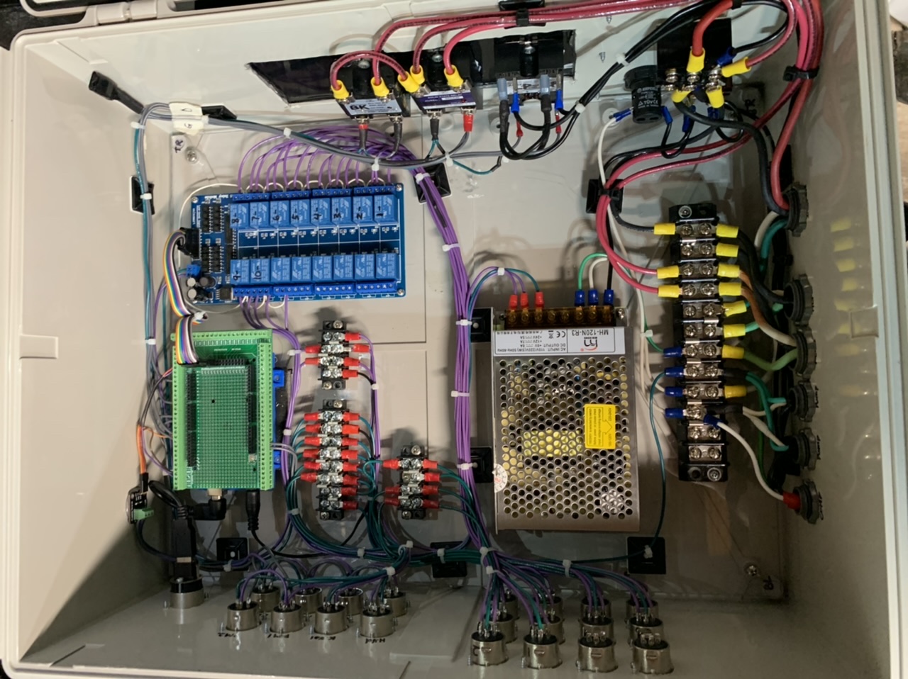
Did you solve this? A schematic and/or pictures of how you have it wired would be helpful. It's really dangerous for us to troubleshoot using descriptions of connections.

Keep in mind that the relay boards may need different voltages for the optos' front-ends than the relay powers.
Still working on it.

I knew you’d want a pic or schematic.
C63CA0CC-E26F-4B2D-825E-37693533D222.jpeg
 
Hi, Brundog, as you know, the RPI is certainly is not as fast as a PC. As you have indicated before, the program is meant to be running full time, and after boot up of about 3.5 minutes with a SSD, BC runs just fine as the overhead of the program is low. It works great for me. I invite others to give it go especially since Windows 11 aims for everone to replace their PCs because of the lack of a TPM 2.0 chip.
 
OK, thanks again for your continual testing and feedback.

My only pushback is the speed... while the cost is certainly interesting, there is a bit of a "get what you pay for" component. And RPi 4, in its usable configuration (8GB, legit SSD, proper cooling), it's not that much cheaper than many mini PC's... especially in the context of the costs of automated brewery hardware.
 
Still working on it.

I knew you’d want a pic or schematic.View attachment 734184

Thanks @BrunDog @TenaCJed @RiverCityBrewer
Turns out I had a couple wires swapped on the two Relays in question. All is well now! I did testing with all valves plugged in and everything is working the way it should.

Now it’s time to finalize my script’s and working on my new plumbing. I’ll hopefully have a start to finish Automatic brew in soon. Buying a new house might slow me down a little bit😀.
 
OK, thanks again for your continual testing and feedback.

My only pushback is the speed... while the cost is certainly interesting, there is a bit of a "get what you pay for" component. And RPi 4, in its usable configuration (8GB, legit SSD, proper cooling), it's not that much cheaper than many mini PC's... especially in the context of the costs of automated brewery hardware.
Oh, and I forgot to mention I have no other way right now to run Win 11 and BruControl... My laptop can't run it.
 
I seem to be having trouble reaching the license server this morning, my install is not licensed, and I'm getting timeouts when I try to activate my license or request an eval license. The system has internet connectivity, so I don't think it's my end. Anybody else having trouble?

- Gregg
 
Back
Top