BruControl: Brewery control & automation software

Homebrew Talk - Beer, Wine, Mead, & Cider Brewing Discussion Forum

Help Support Homebrew Talk - Beer, Wine, Mead, & Cider Brewing Discussion Forum:

This site may earn a commission from merchant affiliate links, including eBay, Amazon, and others.
Any one have any input on the BruControl Quadzilla? I am looking how you wired it and how you control it.

Specifically Voltage and Amperage of supply and how many? 4 x 240vac 10 Amp Circuits?
Wire size and type to Plug from SSR: 12/3 AWG with Ground? (Overkill for 1375 watts)
Plug Type? NEMA L14-20
SSR Proportional with interface PID Outputs like a CRYDOM MCPC Controller? One for each leg? Do you use 0-5v, 0-10v, or 4-20ma control?

I am trying to plan my power outlets in a wall going up this week.

I am looking to see how YOU did it. I am very familiar with Electricity and AWG wire size for Amperage and have an Electrician check my plan. I will properly size the wire after I know how to use the Quadzilla. I am just not sure how you would wire and control the Quadzilla since it is like 4 separate elements.
 
I'm biased, but in my personal rig, the four elements are wired together, via one SSR. Its 5500W @ 240VAC, so ~23A. 10AWG via 12/3 and L6-30P... all wires terminated together (in parallel) in the plug. Given software control, I see no reason to run it at 120VAC. SSR has been binary, will be MCPC 50A model with phase angle control via analog amplifier board AA-1, 0-5V control.

While we made it with four wires... with software control, I honestly don't see any legit reason to run it at 120VAC or anything less than all four wired together to take advantage of lower power density. For example, running two elements at 100% net power will deliver the same heat as four elements at 50% net power. Therefore the heat imparted to wort locally is half with all four elements running.
 
I was wondering about the 4 separate wired Elements. It just seemed you could use PID or Duty Cyle as you stated. Running 4 separate plugs would allow for future changes. Using a 12/3 with ground would give a lot of options. it could be a 120 vac 20 amp circuit, a 240 vac 10 AMP circuit as I thought about. I could use each as I want or change something in the future.

Does anyone use the ELEMENTS Wired Separately?
 
I am using 11.45V to supply MEGA over DC power jack.
Input voltage is declared as 7 - 12V on arduno site.

What's your experience ? Shell I lower the voltage even more ?
 
Is that power supply only for the MEGA? If so, turning down the voltage can ease the load on the regulator, thus letting it run cooler. I have a separate supply for mine and I run it as low as it would turn down to which was about 10.5v.
 
Is that power supply only for the MEGA? If so, turning down the voltage can ease the load on the regulator, thus letting it run cooler. I have a separate supply for mine and I run it as low as it would turn down to which was about 10.5v.
Yes only for MEGA . Thanks!
 
I took a chance on a cheap ESP32 'LOLIN32' board with onboard LiPo battery port and it seems to work well, will put it through it's paces in the next few weeks... I liked the Adafruit feather, but they are up to nearly $30 now... I got 3 for $12 from aliexpress and will be seeing if it, a battery, and 8 RTDs on 2 RP-3 boards in a cantex box works as i hope. US $3.31 19% OFF|ESP32 ESP 32 ESP 32S ESP32S For WeMos Mini D1 Wifi Bluetooth Wireless Board Module Based ESP WROOM 32 Dual Core Mode CPU|Integrated Circuits| - AliExpress

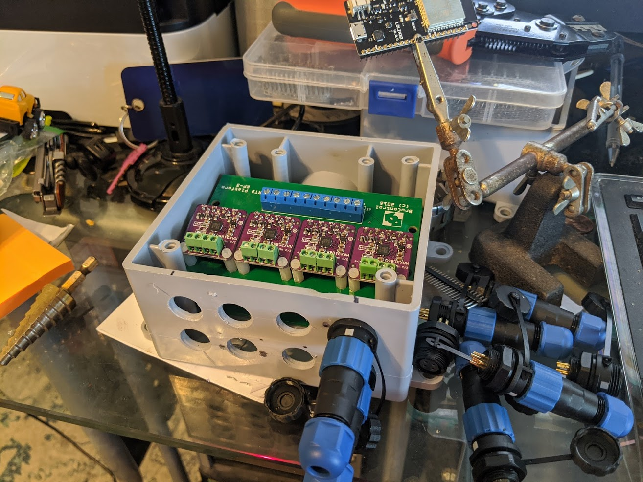
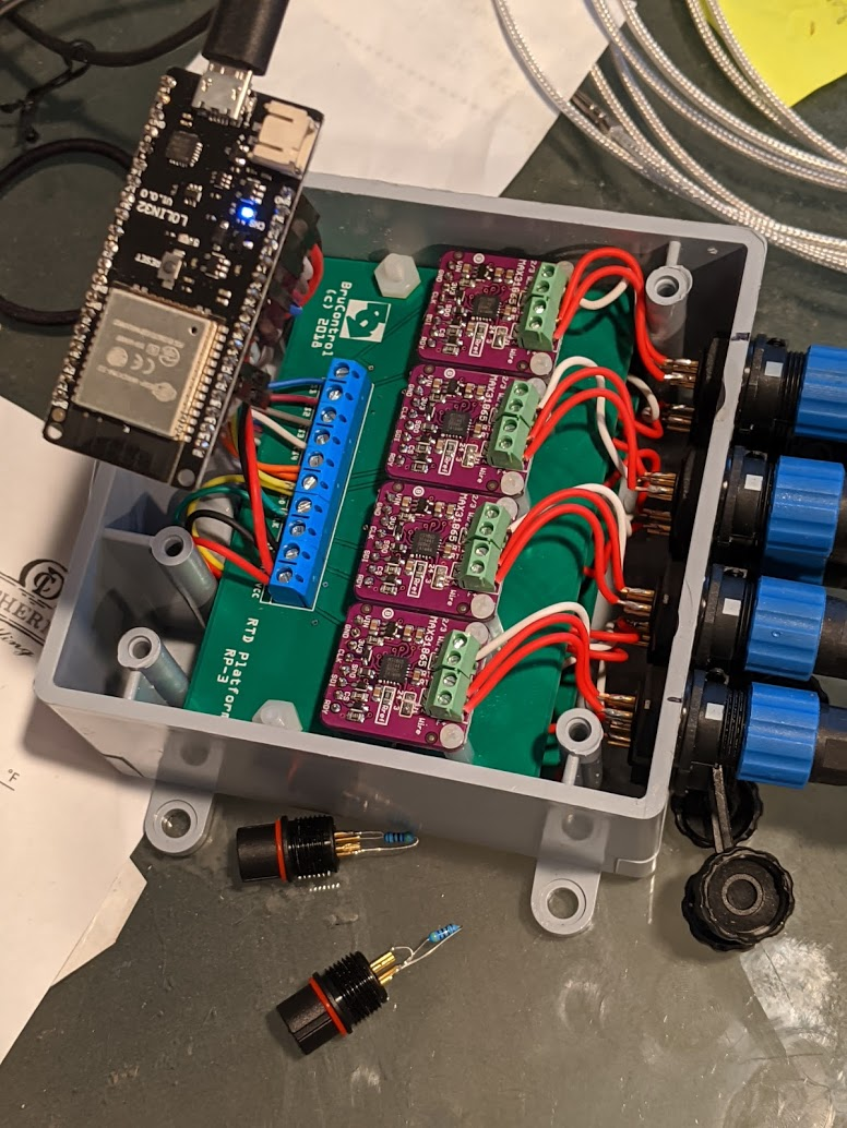
Taking the chance during a conference call this morning to start building my 8 RTD ESP32 Cantex box, I have some nylon standoffs coming, had to sand about 1 mm off each side of the two RP-3 boards stacked in the box, and will have to drill new holes that are not hidden by the rtd amps... This is the LOLIN32 board, and although it works good, and is far cheaper than the adafruit huzzah32, I now realize that it is an older product, and I will use the newer LOLIN D32 Pro V2.0.0 , and maybe even get the 2.4" TFT and fit it in the lid of the box... then if that all works, beg to have code written to show the RTD temps on the touchscreen...
1601392423478.png
 
For anyone that purchased a mega 2560 and an arduino ethernet shield for testing and then later wanted to implement these two devices in a screw-terminal block, other than the excellent brucontrol UM-1 solution, I found someone outside Boston who manufactures screw shields that addresses this problem:

http://crossroadsfencing.com/BobuinoRev17/index.html
If you scroll down to the Mega shield, there is a picture and a description.

He also does custom work, so if you need anything done that you don't see, just contact him. In my case, I wanted to mount the assembly on a DIN rail, so he came up with this solution:
IMG_0733.jpg

In my case, he was super fast in coming up with 3 solutions to the problem (same day) and then ordering in the parts and sending me the completed project. He works on everything Arduino. Hope this helps someone in putting together their system.
 
OK, got the #8-32 standoffs in from digikey, 1/4" on the bottom, 7/8" in between and a hex nut on top, and I may just leave it with 2 standoffs, it will not be subject to movement or vibration when I am done. I wired her up and got 8 RTD's on one ESP32 (big thanks to @BrunDog for making this happen!) I bought some 100ohm 1% resistors and made some test plugs, I will likely make a single test plug for each 100ohm(32F) , 119.4ohms(122F), and 138.52(212F) and work out a procedure to balance the boards. 1% is not really good enough by itself, 99.4 ohms is 29.3 °F or so... I will fiddle with small resistors to get the correct value test plugs for a linear offset and multiplier to calibrate the raw numbers of the RTD Amps before doing calibration of actual probes...
with a single 99.4 ohm resistor as measured on a mediocre quality DMM, here is what the RTD amps output to BruControl:
GPIOraw output∆ RawTemp F∆ °F
12​
7575​
0.375​
29.25​
0.02​
13​
7572​
-2.625​
29.07​
-0.16​
14​
7573​
-1.625​
29.13​
-0.1​
25​
7568​
-6.625​
28.83​
-0.4​
26​
7569​
-5.625​
28.89​
-0.34​
27​
7583​
8.375​
29.74​
0.51​
32​
7581​
6.375​
29.62​
0.39​
33​
7576​
1.375​
29.31​
0.08​
average
7574.625​
Average
29.23​


1601590681896.png
 
Last edited:
Are these results with the same plug (resistor) or different ones?

If same, not bad for brewing but not great for scientific purposes. +0.5 to -0.4 is fairly a +/-0.5 degree variance. Not enough of a sample of course. I do think RTD should return better. Have to check the max31865 datasheet for expected results.

Also, you might measure the reference resistor on these - make sure they are as they say they are.
edited inline to show that it was a single resistor (I did another resistor, and it was about 99.2ohms, and the readings were all about 1.15 degrees F below the 99.4 ohm resistor)... I thought about adjusting the SPI reference resistor value for the device, but not sure exactly how that calculation works. the goal is to get a procedure that anyone can follow when setting these up, and know when they are calibrating correctly and when they are chasing a ghost trying to calibrate something that is not calibratable... adjusting the raw values before the RTD and C-F calc and doing the RTD probe calculation after those also makes it visibly logical when I look at it a year later...
 
I am not sure why you would think the wiring is incorrect. A precise 100 ohm resistor measured with RTD would read 0C or 32°F and 99.4 ohms would be interpolated between 99.35 and 99.57 as being between 29°F and 30°F. What we are seeing here is just a small ∆t of less than 1°F
1601639873503.png

All 8 on this pair of boards work, and I have 12 others that work great in production, so fairly certain it is not a wiring issue.. I used 'Dental Surgical Loupes 2.5x' that I got on amazon to aid with the soldering and cutting, and did a continuity test of the pads as I previously had one incomplete cut.

I hope to write a procedure that separates and therefore simplifies the calibration of the amplifier board and it's inaccuracies versus the actual probe. If I can get all of my RTD Amps reading the same with a single PT100 RTD sensor, and can come up with other calibrations for each sensor that can be moved to any amp. I plan on having 12 RTD's on a 12-plate distillation column where a tenth of a degree F is a big deal, and it is easy to see if something is whacky, as any single probe should never read a higher temp than the probe below it.
 
You will likely define a new calibration sequence for us - very cool and thanks in advance!

Take a look at the data table calibration in BC. You can enter a handful of data points and it will interpolate linearly in between. More points = more accuracy across the range.
 
I would think that you would want the best accuracy in a specific range of temps.

For example, I calibrated my MLT Temp probes specifically at 140F to 158F in one degree increments. Temps above and below that range would make little difference in a Mash. Being off .05 would have no effect. I know that in distillation it is a big difference ( have not done any of that since the 1960's). Obviously you would want it accurate within a narrow range. Looking forward to what you come up with.
 
You will likely define a new calibration sequence for us - very cool and thanks in advance!

don't thank me yet, you know I will ask you to integrate it... question, I do not see it in the manual, can we add/delete/edit calibrations via script?

@oakbarn - yes, along with fermentation temps of 65°F(wort) to93°F (Molasses) I need the absolute best I can get at the 170-180F range, at least a tenth of a degree, hoping for half a tenth, and the way a distillation column works, heat is added only from the bottom, and every plat up is a tiny fraction cooler, but if inaccuracies show that one plate is 176.25 °F and the plate above is 176.28 °F , I know it is wrong because it is a physical impossibility...

End goal? stack 12 of those plates together and you have maybe 5 °F , and then make a fancy color graphic to show me in an instant from across the room that something is awry during the 8 hour run of 1000 gallons of beer sent through the still...
 
You could write a script to change the target as part of a scripted calculation. If you knew that your probe was -.5 off, you could set the target +.5. You could also just use a Global Element to display a corrected temperature.
 
Last edited:
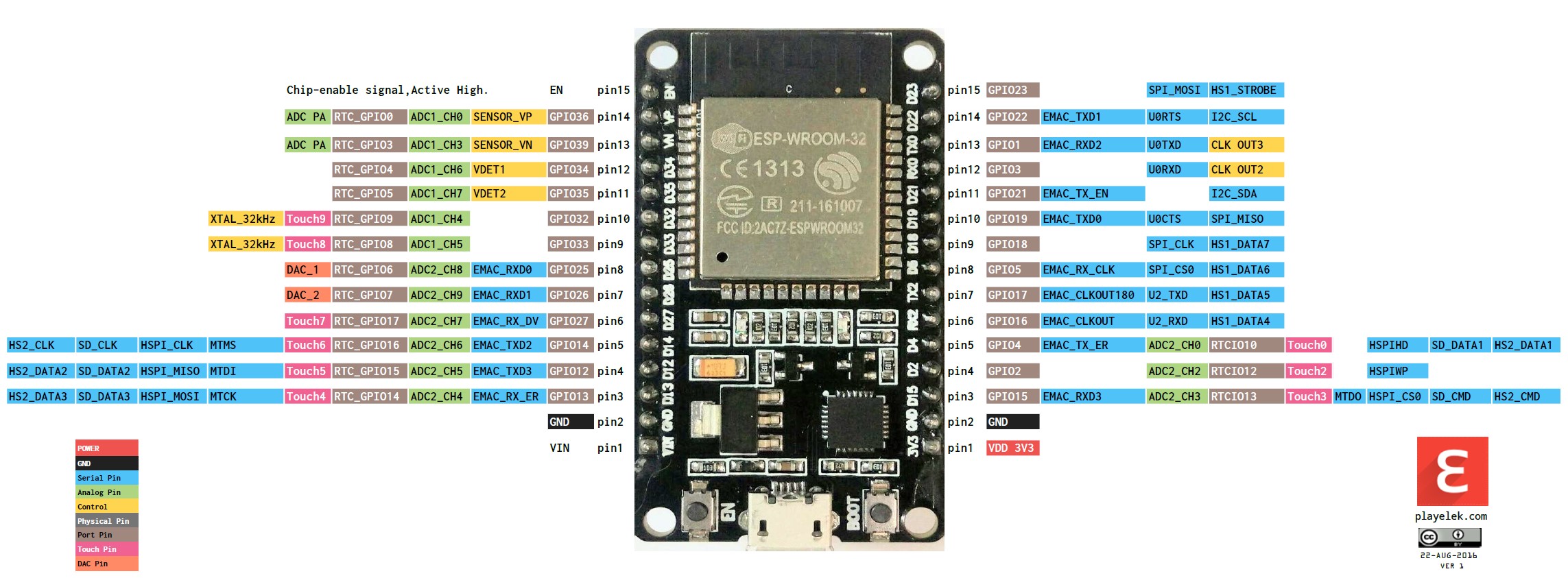
i'm having trouble wiring the rp-3 rtd board to an esp 32. i see it has been asked a few times on this thread but cannot find a definitive guide for the miso mosi and clk connections . can this work on both 5v and 3v supply or only 5v as in the spi advice pdf ? i am using the below board. have tried various combos with no luck. any advice appreciated.
ESP32Espresiffboards12.jpg
 
Last edited:
i'm having trouble wiring the rp-3 rtd board to an esp 32. i see it has been asked a few times on this thread but cannot find a definitive guide for the miso mosi and clk connections . i am using this board. have tried various combos with no luck. any advice appreciated.View attachment 700894

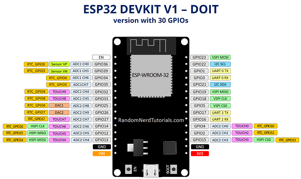
that diagram could be better... you want GPIO18, GPIO19, and GPIO23...

in this diagram they are light green on the right
VSPI CLK
VSPI MISO
VSPI MOSI

1601653552867.png
 
that diagram could be better... you want GPIO18, GPIO19, and GPIO23...

in this diagram they are light green on the right
VSPI CLK
VSPI MISO
VSPI MOSI

thanks thats the connection i have been using to no avail, just getting zero with no calibration or -247 with the 430 calibration added.
 
When using the pressure sensor calibration tool, is the height of the port from the vessel base to the bottom, middle, or top on the sidewall.
 
OK, got the #8-32 standoffs in from digikey, 1/4" on the bottom, 7/8" in between and a hex nut on top, and I may just leave it with 2 standoffs, it will not be subject to movement or vibration when I am done. I wired her up and got 8 RTD's on one ESP32 (big thanks to @BrunDog for making this happen!) I bought some 100ohm 1% resistors and made some test plugs, I will likely make a single test plug for each 100ohm(32F) , 119.4ohms(122F), and 138.52(212F) and work out a procedure to balance the boards. 1% is not really good enough by itself, 99.4 ohms is 29.3 °F or so... I will fiddle with small resistors to get the correct value test plugs for a linear offset and multiplier to calibrate the raw numbers of the RTD Amps before doing calibration of actual probes...
with a single 99.4 ohm resistor as measured on a mediocre quality DMM, here is what the RTD amps output to BruControl:
GPIOraw output∆ RawTemp F∆ °F
12​
7575​
0.375​
29.25​
0.02​
13​
7572​
-2.625​
29.07​
-0.16​
14​
7573​
-1.625​
29.13​
-0.1​
25​
7568​
-6.625​
28.83​
-0.4​
26​
7569​
-5.625​
28.89​
-0.34​
27​
7583​
8.375​
29.74​
0.51​
32​
7581​
6.375​
29.62​
0.39​
33​
7576​
1.375​
29.31​
0.08​
average
7574.625​
Average
29.23​


View attachment 700811
I am following this, although I decided to switch to NTC, still keeping RTD connected. :)
Note: I am not an expert,below is only from my experience and sorry if I am jumping here in with superfluous info.

I have experience with cheap RTD100 and purple boards. Just my 2 cents to the topic:
Boards from Adafruit are much better quality, stability and reference resistor is matching what's written, but I'd still measure it.
I ended up throwing those purple away (mine were from AliE) as they were unusable. Cheap sensors (30-35$) are - what they are - cheap - what you get. AliE or Ebay it's all the same. If you dont know what's good, ask for the price. :)
And results you are getting are reminding me of my nightmares with them.

Wires for sensor are super important (probably you used copper everywhere).
More wires - more accuracy - if I am not mistaken, 3 wire sensor could offer max accuracy of 0.3C (depending on the sensor and range) and only with 4 wires accuracy one can go up to 0.1C (I wasn't able to achieve it).

However every sensor you buy should have declared/measured (trusted) accuracy. Cheap ones, even with 3 wires are likely with low - 0.5C accuracy.
I tired buying one expensive, 3 wire sensor (more than 100$, seen the sensors of 300$) form professional Swiss sensor shop and it was huge difference. Anything made from platinum has to cost a lot, it needs to be with certificate and if you want it with minimum impurities and accurate to 0.1C.
When checking prices (in certified shops) it seems such hi-accurate. 4 x 4 wire sensor system could cost easily 1200$ (4 Sensors x 300$). I don't think it's needed but just sayin'.

cheers
 
Last edited:
I am following this, although I decided to switch to NTC, still keeping RTD connected. :)
Note: I am not an expert,below is only from my experience and sorry if I am jumping here in with superfluous info.

I have experience with cheap RTD100 and purple boards. Just my 2 cents to the topic:
Boards from Adafruit are much better quality, stability and reference resistor is matching what's written, but I'd still measure it.
I ended up throwing those purple away (mine were from AliE) as they were unusable. Cheap sensors (30-35$) are - what they are - cheap - what you get. AliE or Ebay it's all the same. If you dont know what's good, ask for the price. :)
And results you are getting are reminding me of my nightmares with them.

Wires for sensor are super important (probably you used copper everywhere).
More wires - more accuracy - if I am not mistaken, 3 wire sensor could offer max accuracy of 0.3C (depending on the sensor and range) and only with 4 wires accuracy one can go up to 0.1C (I wasn't able to achieve it).

However every sensor you buy should have declared/measured (trusted) accuracy. Cheap ones, even with 3 wires are likely with low - 0.5C accuracy.
I tired buying one expensive, 3 wire sensor (more than 100$, seen the sensors of 300$) form professional Swiss sensor shop and it was huge difference. Anything made from platinum has to cost a lot, it needs to be with certificate and if you want it with minimum impurities and accurate to 0.1C.
When checking prices (in certified shops) it seems such hi-accurate. 4 x 4 wire sensor system could cost easily 1200$ (4 Sensors x 300$). I don't think it's needed but just sayin'.

cheers

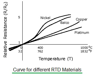
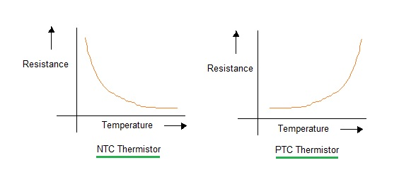
NTC is basically a 2-wire RTD with a very unlinear curve, the S-H calibrations for that curve make it readable.. even a copper RTD blows it away for linearity...
1601815969768.png
1601815981577.png


Adafruit boards may have been the high quality ones in the past, but my previous post last December on this subject showed they were not as close to the actual temp as the average aliexpress unit. I have both now, 14 aliexpress ones and 2 adafruit ones, I did not have your experience.

I get my wire from Digikey, it is shielded carol C2526 22AWG cable, but have only used it on 1-wire sensors so far, I order the RTD's with the proper length cable to go directly to the box. with gold plated pins and 2" long 22awg TXL wire internal on the box to go to the RP-3 board. But in this case, I am using resistors, not probes and moving from jack to jack, with repeatable differences, which are *likely* small differences in the 430ohm calibration resistor, and the aliexpress ones are closer to the true value than my particular adafruit ones.

I completely understand that $300 probes are better than $10 ones... not gonna argue that, but also not going to buy 20 of the $300 ones when I can, with calibration, get the $10 ones to work 99% as good for what we are doing here.


Most accurate are 4 wire probes.
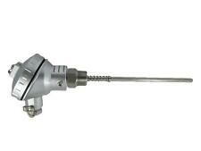
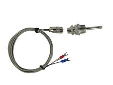
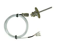
The number of wires is important for long distances, and there is a difference between 3 and 4 wire, but not nearly as much of a difference when going from 2 to 3 wire. 3-wire is a good compromise, and when you take into account the number of probes out there for 3-wire is huge, 3-wire is a no-brainer. You want a probe with a spring loaded tip and a housing, a probe with a quick disconnect and NPT, or a probe with a 1/5" TC port and a QD??? all 3 have worked for me personally and all 3 are easily orderable on eBay and aliexpress and they will customize probe and cable length
1601813139190.png
1601813159828.png
1601813122624.png

These are all available from the eBay seller "Sensors_factory".
 
I agree with above... my only addition is the connector itself can also add small resistances. I sweat this much more than the wire itself. It would be interesting (if you are willing) to wire the resistor directly into the amplifier terminals and repeat the tests - see if there is any meaningful difference. The resistance curve slope is so flat that every minor difference shows up.

Regarding the amps, assuming the MAX chip is used on both, I would be pretty confident they are comparable. This is adafruit's design that was (unscrupulously) copied by overseas manufacturers. The resistor would and other supporting hardware (terminal blocks, etc.) could be of lesser quality.
 
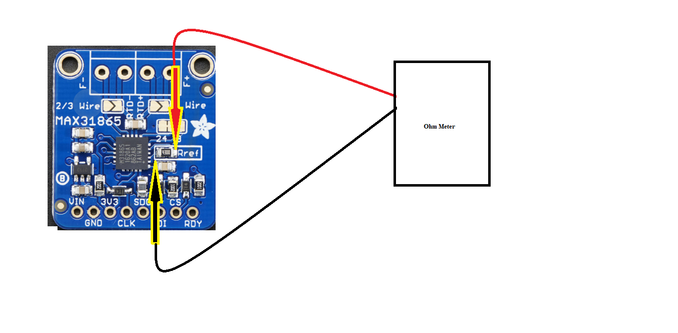
Am I doing something wrong? I am trying to measure the reference resistor. The pix is for a pt1000 but I have the PT100 430 Resistor amps.

I tested 3 and got no readings or even continuity. I would assume that you just put the probes on the ends of the resistor.

test resitor.png
 
Ya that’s the problem with in-circuit measurement. If the circuitry around the resistor lets the electrons flow, then you aren’t reading just the resistor. Try reversing the probes and see if it reports differently.
 
Ya that’s the problem with in-circuit measurement. If the circuitry around the resistor lets the electrons flow, then you aren’t reading just the resistor. Try reversing the probes and see if it reports differently.
No difference. I am using a Klien MM400 Autoranging Multimeter. I do not have any loose resistors laying around at the moment to check the meter but is it brand new.
 
I agree with above... my only addition is the connector itself can also add small resistances. I sweat this much more than the wire itself. It would be interesting (if you are willing) to wire the resistor directly into the amplifier terminals and repeat the tests - see if there is any meaningful difference. The resistance curve slope is so flat that every minor difference shows up.

Regarding the amps, assuming the MAX chip is used on both, I would be pretty confident they are comparable. This is adafruit's design that was (unscrupulously) copied by overseas manufacturers. The resistor would and other supporting hardware (terminal blocks, etc.) could be of lesser quality.
To test the same resistor, I will make a plug connector that goes to screw terminals like the RTD amp boards have and test with the resistor directly in theRTD Amp, and then the plug with the same resistor attached, and test on all boards. Although it will take some time to check all 8 now that it is assembled, it will be a great check to ensure that each and very connector is correct and not influencing the reading. I will say that the connectors are certainly better than my hands holding the probe tips to the resistor leads while they are on the tape they ship on!
 
NTC is basically a 2-wire RTD with a very unlinear curve, the S-H calibrations for that curve make it readable.. even a copper RTD blows it away for linearity...
View attachment 701171View attachment 701172

Adafruit boards may have been the high quality ones in the past, but my previous post last December on this subject showed they were not as close to the actual temp as the average aliexpress unit. I have both now, 14 aliexpress ones and 2 adafruit ones, I did not have your experience.

I get my wire from Digikey, it is shielded carol C2526 22AWG cable, but have only used it on 1-wire sensors so far, I order the RTD's with the proper length cable to go directly to the box. with gold plated pins and 2" long 22awg TXL wire internal on the box to go to the RP-3 board. But in this case, I am using resistors, not probes and moving from jack to jack, with repeatable differences, which are *likely* small differences in the 430ohm calibration resistor, and the aliexpress ones are closer to the true value than my particular adafruit ones.

I completely understand that $300 probes are better than $10 ones... not gonna argue that, but also not going to buy 20 of the $300 ones when I can, with calibration, get the $10 ones to work 99% as good for what we are doing here.


The number of wires is important for long distances, and there is a difference between 3 and 4 wire, but not nearly as much of a difference when going from 2 to 3 wire. 3-wire is a good compromise, and when you take into account the number of probes out there for 3-wire is huge, 3-wire is a no-brainer. You want a probe with a spring loaded tip and a housing, a probe with a quick disconnect and NPT, or a probe with a 1/5" TC port and a QD??? all 3 have worked for me personally and all 3 are easily orderable on eBay and aliexpress and they will customize probe and cable length
View attachment 701169View attachment 701170View attachment 701168
These are all available from the eBay seller "Sensors_factory".

Here is from where I am coming from.

Mort from the group gave me following hints below when I started and I totally think they are valid and make sense.

Please not that - I am mostly focused on PID usage. If you are not there, please disregard my post.

I started using NTC because it is true analog input to BC and I think they are best for PID and for BC.

As you know RTD is not directly connected. It needs AD convertor amplifier / bridge module which has side effects:
1) Communication can be interrupted/ influenced by disturbance - experienced that in my builds (brundog knows) and never had that with NTC. If it's like that it would 'reeboot'.

2)Then, when the interface boots or when it's disturbed it starts from -600C and then counts up to actual temperature. If it's used for PIDs, it will push output to 100% because of the error. I can confirm this for tests I did.
NTC don't do this and in all imperfection it's the most optimal sensor in terms of price/quality IMHO.

Just my 2 cents.
 
Yes, having the RTD not be autonomous is not ideal... hoping that is someday changed. If you are using PID and you have RTD on an interface that is glitchy, you will lose/gain a few seconds of heating, but the PID is designed to make up for this if properly tuned. more annoying to me are the graph spikes throwing the outranging off, but heck, I get that with 1-wire... I have had most of my glitches go away with newer interface firmware, and the one where the interface disconnects has not happened since I used the ESP32 with a LiPo battery.
 
Back
Top