helibrewer
Well-Known Member
Also need to know how you have it wired.
Pos to 12VDC+
Neg to 12VDC-
Data to Port 19
Last edited:

Also need to know how you have it wired.
Eek... you may be putting 12VDC into your pin 19. You should measure the voltage out of the flowmeter and slowly turn the turbine inside to see it alternate between positive voltage and ground. If it outputs what the input voltage is, you will indeed see 12VDC on that pin. If it only outputs 5V max, then you are OK.


![Craft A Brew - Safale S-04 Dry Yeast - Fermentis - English Ale Dry Yeast - For English and American Ales and Hard Apple Ciders - Ingredients for Home Brewing - Beer Making Supplies - [1 Pack]](https://m.media-amazon.com/images/I/41fVGNh6JfL._SL500_.jpg)


so we should revert to build 9 for now?Yup... agreed. I see what happened. Hold on while we fix it! I'm going to remove it for now.
so we should revert to build 9 for now?
This is kinda neat. Forces inputs to be inputs and outputs to be outputs, and upside down MEGA design essentially prevents any shields, but the price is good. I ordered one to mess with it:
https://www.tindie.com/products/universalsolder/fully-loaded-diy-plc-48-io-for-arduino-mega2560/
I like the Robot Shop Ethermega ( EtherMega Ethernet Arduino Compatible Microcontroller) Mega as the power regulator is beefed up. Says it can take up to 28 vdc input without overheating. A bit more $ than the Robodyn but a more robust one.Well, I got this bad boy and was severely dissappointed to see they left out the 2x3 ICSP header!! Shame, Shame, Shame!!
That renders this essentially useless for non-serial applications until we have a MEGA format board with on-board Wi-Fi. I'm assuming Adafruit will make a Grand Central with one at some point... they made the Metro with one. Actually... the SPI pins are exposed, so you *could* connect a Wi-Fi module next to it. Still, such an easy miss!
Edit: I should have said onboard network... and forgot about the Robotdyn MEGA which has the Ethernet on board.
What would you use a thin client for?it ends in 3 hours, but will likely get renewed.. Dell Wyse 5070 Extended Thin Client J5005 1.5Ghz 8GB 16GB AMD Video Card ThinOS | eBay
What would you use a thin client for?
The alternative that I implemented was to use brewpiless on either esp32 or esp8266 to capture the iSpindel data, and then pass it on to a node-red server, which in turn formats the data so that it can upload it through Data Exchage into Brucontrol. With the esp32 you can also capture autospunding data from the latest brewpiless firmware update. I've tried all of it and it works. If anyone is interested, PM me and I am happy to share the the links for my install of brewpiless and the node-red flow. Admitedly it's a bit of a work around, but it was the fastest way for me to accomplish what you are after given that I already had iSpindel integration. Not trying to proselytize other software, just trying to provide work arounds that hopefully help.hi , is there a thread or discussion on here about the process for integrating the ispindel with brucontrol professional ? the ispindel i have is on esp8266. i have it set up with ubidots at the minute.
") . Until then I am reading posts from this thread and learning
. Until then I am reading posts from this thread and learning Simple answer, it depends. The more/faster CPU/memory/storage resources you have available on the BC computer, and the faster the network speed, the higher the IO throughput. The API calls are HTTP based, so I would think a couple hundred a second at a minimum with a basic computer on a wired connection.Question: What is the maximum number of calls to/from the Data Exchange protocol and the unit of time?
Thanks.Simple answer, it depends. The more/faster CPU/memory/storage resources you have available on the BC computer, and the faster the network speed, the higher the IO throughput. The API calls are HTTP based, so I would think a couple hundred a second at a minimum with a basic computer on a wired connection.
Can you reset via the New Direct Command? If so, an example?Yes. Just a good practice IMO to reset after saving the network settings.
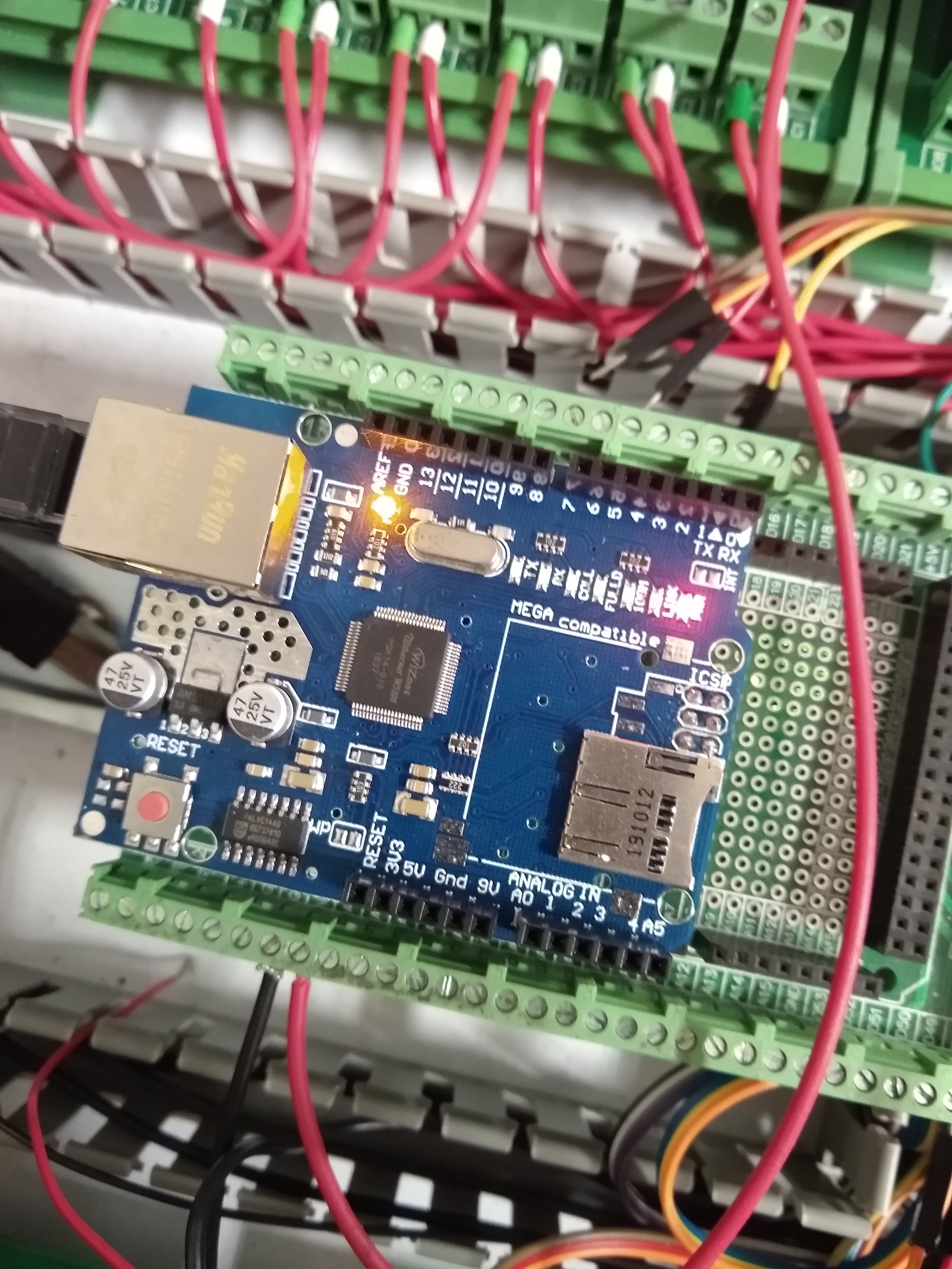
Ok I'm at the brewery today and will give this a shot.Based on your description above, it sounds like your MEGA's regulator is overheating. See if you can touch it and feel it get very hot. This is a known problem on some of the copies. I know this is whacky sounding, but true. The regulator has to dump any excess voltage from its input to its output (12V down to 5V). Some MEGA's are well designed with an on-board sinking surface (exposed copper with connections between top and bottom) and some are not, possibly even using less robust regulators. A pic of that area might help us diagnose it, or a link to the exact one you have.
Is there anyway you can lower the voltage going into it from the 12VDC power supply? Meaning, if your power supply has an adjustment, can you make it lower (say, to 11 volts). If not, do you have a fresh 9V battery handy? If so, try it with that for a while.
You might be able to put a small adhesive heat sink on it to get it from overheating. It looks like you are using a W5100 Ethernet Shield... it might be better to switch to the W5500 which I believe uses less current too.
Also, per previous discussions on this... you should remove the screw shield and see if this behavior continues. If by some odd circumstance you have resistive short somewhere, that could also be pulling more power from the MEGA than it likes.
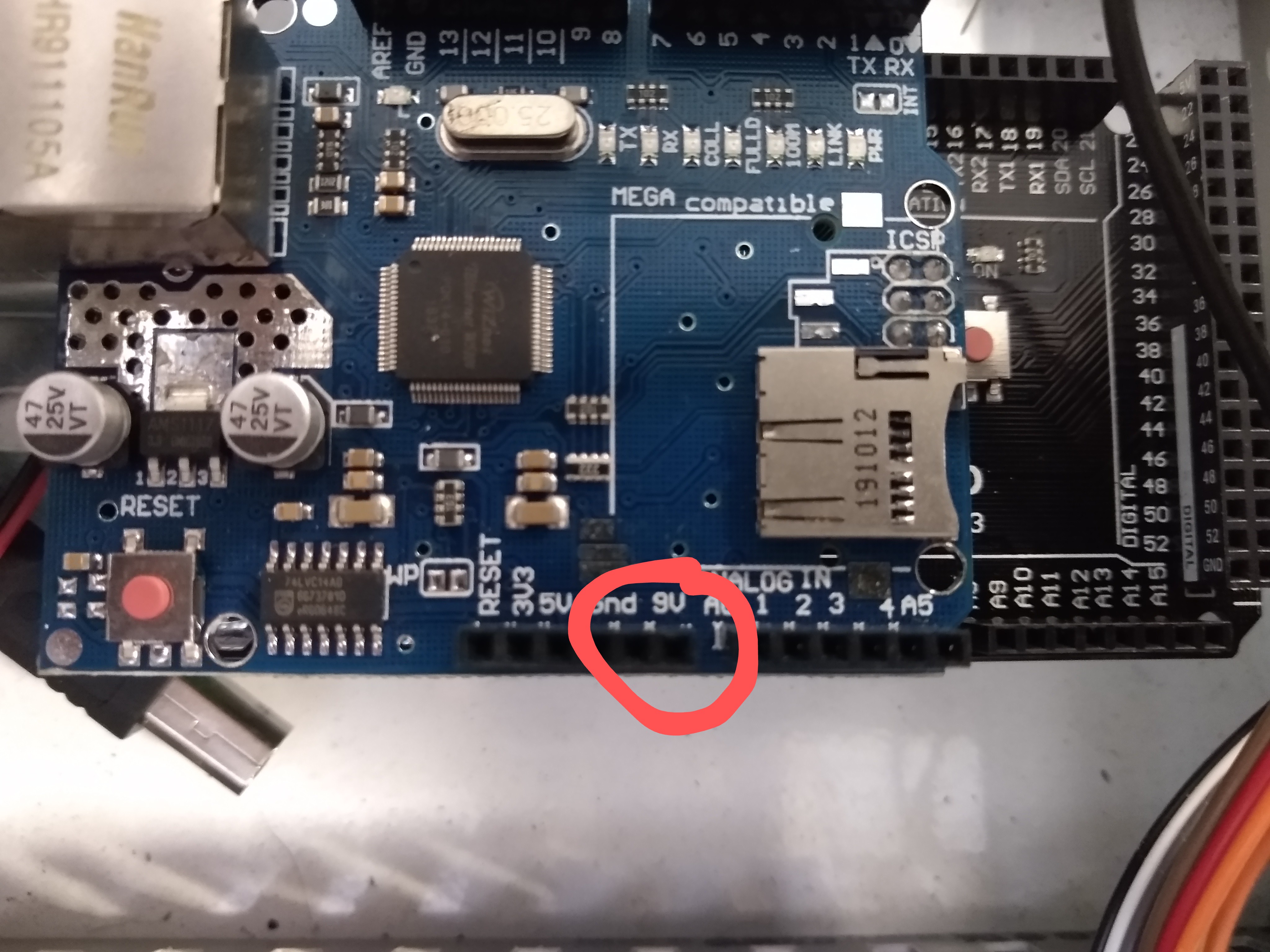
The VIN socket on Mega aligns with the 9v pin on the W5100. Since the W5100 is mounted to the mega I have to supply power through the socket on W5100 correct?Not sure where you see the W5100 calls for 9V. It does not in fact run on anything more than 5V. That comes from the Mega via its power regulator. I’m saying power the mega with 9V via the Vin pin instead of 12V and see if it runs ok.
5V and 3.7V are not relevant here as we are tying to see if 12V at the mega is the problem.
Curious why 12V VIN on screw shield is directly connected to the W5100 9V port.I do not think the W5100 uses that pin. the official sunfounder site PCB photos look to not have that pin actually connected to the circuitry of the W5100.
Edit: I see what your saying. It must just be there for stability. Since I don't have the screw shield in place, I should power through this pin since this is connected to Mega VIN port correct?I do not think the W5100 uses that pin. the official sunfounder site PCB photos look to not have that pin actually connected to the circuitry of the W5100.
I got everything stable today with bypassing screw shield. Not sure if it's that yet, I just reistalled to check of the issue arises. The issue could be the resistor issue you linked. I do infact have 510 labeled on this resistor set.Yes, correct. I checked my W5100 (Ethernet Shield 1) and I see no traces going to that pin. Checking the schematic, that pin is not connected, so this makes sense. It is just there as a pass-through. The 5V power it uses comes from the MEGA. When your MEGA is powered via USB (5V), the regulator is bypassed. When it is powered by 6-12V on VIn or 7-12 on the jack, it goes through the regulator. Oooh.. which gives me an idea. The Jack has a protection diode on it... it will cause a ~0.7V drop on the input. You could power your 12V there and get the benefit of a slightly reduced voltage to the regulator.
That said, I did come across this article... might check it to see if this affects you: Arduino Ethernet W5100 – how to fix the wrong board
I assumed I had the wrong to be based on this excerpt from the article. Out of curiosity why isn't 510 on the list?If you see “510” on that resistor array, then you have the right ones.