Lots to digest / regurgitate...
1. Let's not get wrapped up in PID or hysteresis. Either will work fine. Heating water is straightforward and doesn't need advanced controls since as soon as you stop heating, the temp stops rising (unlike certain systems which have inherent "momentum"). BC will give you several options for controlling outputs (to the interface) and you have choose or use them at will. This is a software thing and does not care much about the downstream hardware.
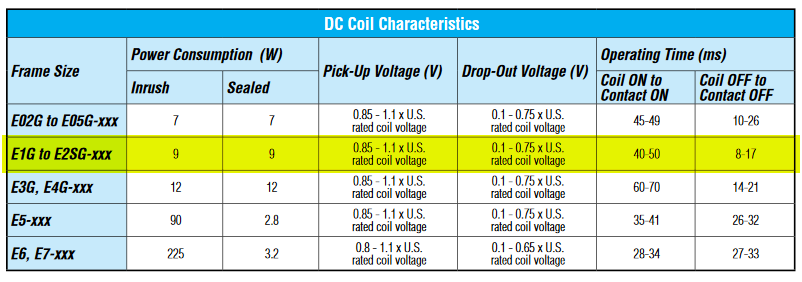
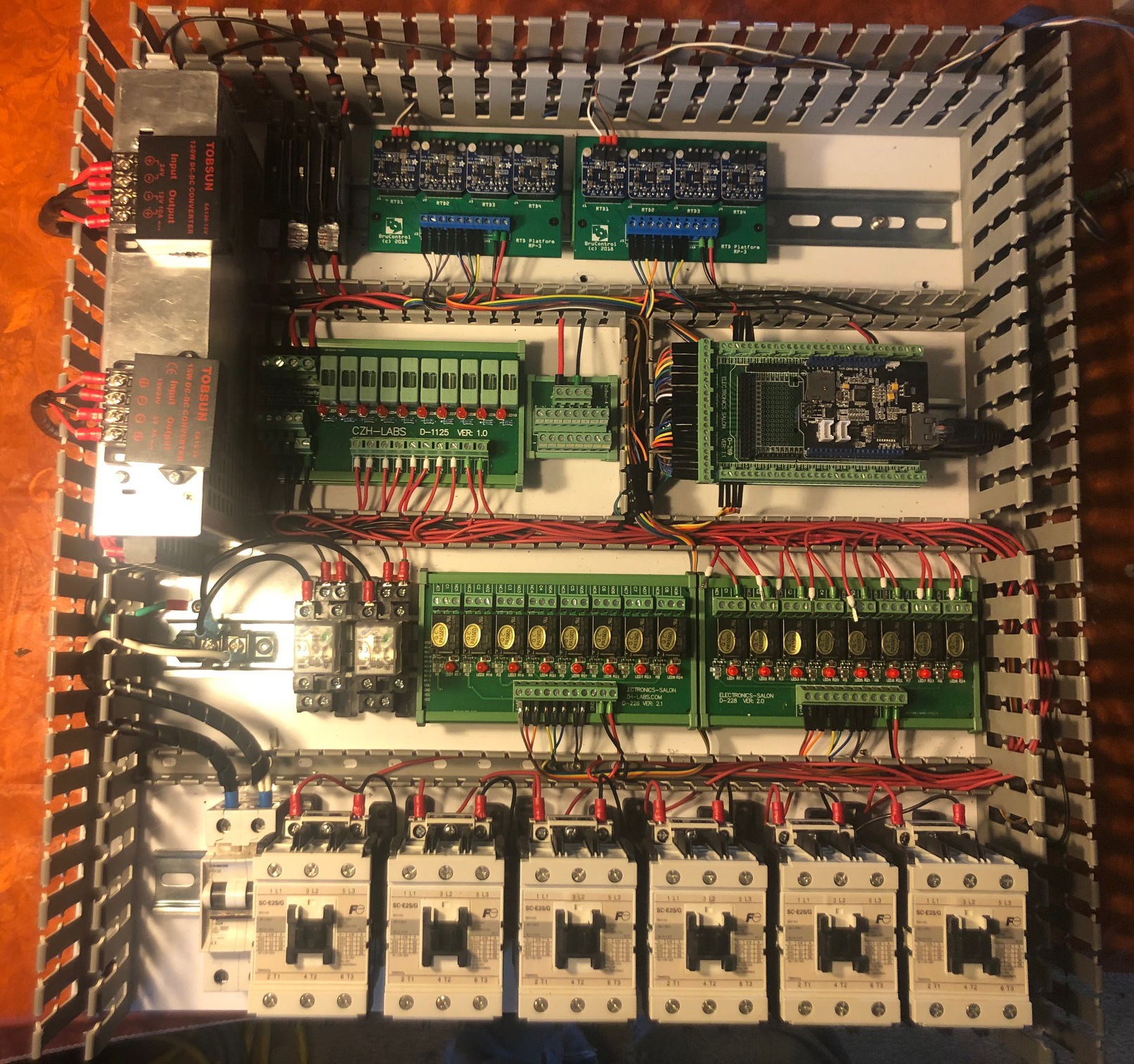
2. You do not *need* SSR's, but you want them. You will need to manage EMI induced from inductive loads. Heating elements are not inductive and will not create noise when turning them on or off. SSRs are also not inductive and will not induce (pun intended) noise. I suggest zero-cross SSRs which will only switch when the potential across them is zero. Contactors are inductive themselves, and will produce noise two ways: First when discharging the contactor coil and when an arc is created across the opening contacts during full current (random due to sinusoidal current flow). Worse, you typically have a relay switching the contactor, which means TWO coils and sets of contacts. The relay boards typically have flyback diodes for their coils, but your contactors wont (and will need either diodes if DC or snubbers/MOV's if AC). So that said, I would recommend a contactor to switch power for safety and an SSR for switching power to elements from the interface output in #1 above. You need the contactor because a. the SSR will only switch one leg of the 240VAC circuit (unless you use 3 phase SSRs or 2x and switch both legs) and b. even then, they have leakage voltage (when its "off", you want it off) and c. when SSR's fail - they typically fail stuck ON.
3. Now regarding your size... you should select components that physically and feasibly meet the specifications. You can either use ONE contactor and ONE SSR tied to THREE elements - so long as the contactor, SSR, and associated wiring/circuit protection, terminal connections, etc. can handle the load. Alternatively, you could use ONE contactor, and THREE SSR's. Or THREE contactors and THREE SSRs. In this last config, you are basically running three circuits in parallel, but in the last two you could have discreet control over each SSR, meaning you could run one differently than the other - maybe that's a benefit to reduce power - dunno. You could run those 3x SSR's off one output (though SSR's draw ~12mA, so that's 36mA so you would need an intermediate transistorized circuit), or run each SSR off a different MEGA pin/port.
Lots of ramblings... sorry quarantine's got me nutty! Anyway, if it were me, and if you are looking for a recommendation in the weeds of the forrest I just grew for you, I would do as few contactors as needed to switch the load for safety, then one SSR per element. If it's three phase power you are switching, you will need 3 phase SSR's. You can run multiple PIDs driving multiple SSRs simultaneously, referencing the same input temp probe, and they will switch at exactly the same time.
Did you say you have schematic?


![Craft A Brew - Safale BE-256 Yeast - Fermentis - Belgian Ale Dry Yeast - For Belgian & Strong Ales - Ingredients for Home Brewing - Beer Making Supplies - [3 Pack]](https://m.media-amazon.com/images/I/51bcKEwQmWL._SL500_.jpg)


