• Please visit and share your knowledge at our sister communities:
  • If you have not, please join our official Homebrewing Facebook Group!

    Homebrewing Facebook Group

BruControl: Brewery control & automation software

Homebrew Talk

Help Support Homebrew Talk:

This site may earn a commission from merchant affiliate links, including eBay, Amazon, and others.
Simple Error with simi dire consequences

This is NOT an issue with BruControl but an error on my part.o_O

I created an endless loop in a script with the start command.

I had a script named Script 5

A it did lots of things, but at the end of the Script I put
start "Script 5"

Everytime it reached the command, it re ran, and re ran, and re ran, endlessly. BruControl gave an error and basically locked. I could not quit or continue. I had to use the Power switch on my computer to force a shut down.

I deleted some program logs and generally cleaned the computer with a utility.

I did not lose anything and I was able to fix the script.

So FYI: Be careful using the start command so you do not create an endless loop!!:rolleyes:

The start command worked as it should, this was MY error.
 
problem with if end if logic

I have the following code:

new string vSMsg
new string vSMsg1
new string vSMsg2
new string vSHopOZ
new string vSHopName
new string vSDropTime
new string vSMsgSpacer
new bool vBStartofBoilHops
vBStartofBoilHops = true
vSMsgSpacer = " "
[Start of Boil Hops]
if vBStartofBoilHops == true
"gblS_HopMessage_ALARM" displayname = "Bitter Hops at the Start of Boil! "
//
[Hop1]
// some other stuff for vSMsg
[End Start of Boil Hops]
"gblS_HopMessage_ALARM" value = vSMsg
endif
//
clear
stop "scrHopMsgDrop"


My issue is that I am getting an error :

[ERROR Line 0: 'end' statement without preceding conditional]

if I change to

new string vSMsg
new string vSMsg1
new string vSMsg2
new string vSHopOZ
new string vSHopName
new string vSDropTime
new string vSMsgSpacer
new bool vBStartofBoilHops
vBStartofBoilHops = true
vSMsgSpacer = " "
[Start of Boil Hops]
if vBStartofBoilHops == true
"gblS_HopMessage_ALARM" displayname = "Bitter Hops at the Start of Boil! "
//
[Hop1]
some other stuff for vSMsg
[End Start of Boil Hops]
"gblS_HopMessage_ALARM" value = vSMsg
//endif
//

it runs fine. So I have an if without an endif!

//some other stuff for vSMsg is a bunch of nested if endif statements that also work fine without that final endif.
 
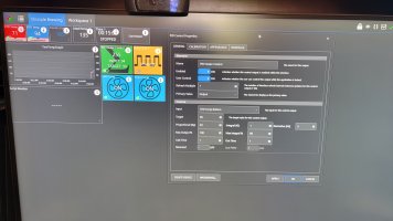
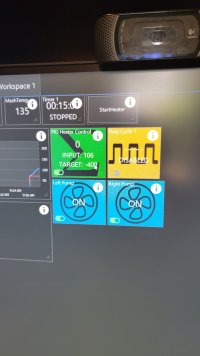
I'm running 1.1 build 22 with an esp32. I have 2 RTDs working and a duty cycle output working just fine to control a heating element through SSR. I am having trouble with the PID control however. The output from the PID remains at 255 even when input is greater than target. The only way I can get the PID output to go to zero is to make the target a large negative number (i.e. -400)
Any insight as to what I have set incorrectly here?
 

Attachments

  • 20230414_094315.jpg
    20230414_094315.jpg
    6.1 MB
  • 20230414_094659.jpg
    20230414_094659.jpg
    894.4 KB
Hard to tell without an output trend, but I would bet you are experiencing intergal windup (Ki). Try setting that value lower. I'm not saying this value will work for you, but for reference, my Ki for my mash PID is .02

Also, increase your calc and output time. 5-10 seconds should be sufficient in a standard water heating system.
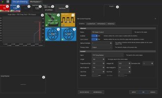
Thank you for the suggestion. Even with those adjustments, it still continue heating. I even attempted a target of -100 and it kept a 255 output. Only when I set the target at something drastic like -400 did it change the output to 0 (those are the dips in the red line). Attached is the trend of the RTD temp (Input to PID control) and the PID output. Please let me know you have any other suggestions.
 

Attachments

  • PIDpic.JPG
    PIDpic.JPG
    301 KB
Yes, no difference. If it is helpful, I tried hysteresis control and am having trouble getting it to toggle as well. It just stays on.
 

Attachments

  • PIDpic.JPG
    PIDpic.JPG
    300.4 KB
That is quite strange. Can you post what board and what pin you are using for control, as well as what kind of relay you are controlling?
 

Attachments

  • 20230414_151217.jpg
    20230414_151217.jpg
    862.9 KB
Hmm, it looks like that should be working ok. Have you tried a different pin on the board to rule it out? Also, what firmware are you running?
 
I am trying to hook up some Valves that are powered on and powered off. They are not reverse polarity but have a Negative and two + leads. I am using a Relay to switch. When the Element is Off, it is fine, but when I turn the Element on, it pulses On then Off fairly rapidly {and the valve is moving slighly with the pulses. When I hook them up to the Mega (or Grand Central), the relay pulses on and off. I have thought it might be the relay but I changed the relay out out. Any ideas?
 
OK, I found it;
Name>Prop Valve</Name>
<UserControl>true</UserControl>
<Width>260</Width>
<X>90</X>
<Y>540</Y>

Still no trace of this Element on my actual workspace; could I delete it from the backup config file and then somehow upload to Brucontrol?
I've noticed that there have been a number of posts about elements going missing, scripts being lost, and/or even unintended consequeses from naming conventions in elements that were later picked up in scripts. This causes a lot of time being spent on searching for items or trying to debug. I had the same problem when my windows machine crashed and I was trying to rebuild what I had done before. While all the advice given in this forum is excellent, my personal approach to the problem was to use node-red to walk through the xml contained in backup brucontrol files (see above for how to find them) to pull out all the instances of the workspaces, the element names contained in each, the type of element and the id of the element. While it may seem tp be too much of an additional burden to implement node-red--depending on what you are looking for--I'm including my node-red flow as an example of what it can do: (copy and paste the import this code as a new flow in node-red)

Code:
[
    {
        "id": "3650d7a4f00805cd",
        "type": "tab",
        "label": "Find Brucontrol Elements by Workspace",
        "disabled": false,
        "info": ""
    },
    {
        "id": "1adf9c33a16a2580",
        "type": "xml",
        "z": "3650d7a4f00805cd",
        "name": "xml --> js object",
        "property": "payload",
        "attr": "",
        "chr": "",
        "x": 320,
        "y": 120,
        "wires": [
            [
                "0d2dafbdd04e43d5",
                "ec7022b3cb16c45e"
            ]
        ]
    },
    {
        "id": "0d2dafbdd04e43d5",
        "type": "function",
        "z": "3650d7a4f00805cd",
        "name": "js object to rows",
        "func": "/*\npayload.Configuration.Workspaces[].Workspace[].Name[]\npayload.Configuration.Workspaces[].Workspace[].Elements[].Element[].Name[]\npayload.Configuration.Workspaces[].Workspace[].Elements[].Element[].ID[]\n\n04/25/23\n\npayload.Configuration.Workspaces[0].Workspace[0].Name[0]\npayload.Configuration.Workspaces[0].Workspace[0].Elements[0].Element[0].Name[0]\npayload.Configuration.Workspaces[0].Workspace[0].Elements[0].Element[0].ID[0]\n\npayload.Configuration.Workspaces\npayload.Configuration.Workspaces[0].Workspace\n*/\n\nmsg.originalData = msg.payload; //save in msg (for debugging)\n\nvar workspaces = msg.payload.Configuration.Workspaces[0].Workspace;\n//var workspaces = msg.payload.Configuration.Workspaces.Workspace;\n//var workspaces = msg.payload.Configuration.Workspaces;\n\n//workspace name get name\nvar wsName = 1;\nvar rows = [];\nfor (let iWS = 0; iWS < workspaces.length; iWS++) {\n    let workspace = workspaces[iWS];\n    let elements = workspace.Elements[0].Element;\n    let workspaceName = workspace.Name[0];\n    let workspaceRows = elements.map(el => {\n        return {\n            workspace: workspaceName,\n            id:   el.ID[0],\n            name:   el.Name[0],\n            type:   el.$[\"i:type\"],\n        }\n    })\n    rows.push(...workspaceRows)\n}\nmsg.payload = rows;\nreturn msg;\n",
        "outputs": 1,
        "noerr": 0,
        "initialize": "",
        "finalize": "",
        "libs": [],
        "x": 320,
        "y": 180,
        "wires": [
            [
                "aa64322c2ebdc794"
            ]
        ]
    },
    {
        "id": "aa64322c2ebdc794",
        "type": "csv",
        "z": "3650d7a4f00805cd",
        "name": "",
        "sep": ",",
        "hdrin": "",
        "hdrout": "all",
        "multi": "mult",
        "ret": "\\n",
        "temp": "workspace,name,type,id",
        "skip": "0",
        "strings": true,
        "include_empty_strings": "",
        "include_null_values": "",
        "x": 510,
        "y": 180,
        "wires": [
            [
                "fcd6d0634d779913"
            ]
        ]
    },
    {
        "id": "8f33db8d99d2624f",
        "type": "comment",
        "z": "3650d7a4f00805cd",
        "name": "____Use this path as a model for your path to 'UniFlex_3V_BinarySSR.brucfg'(XML) under Brucontrol folder ___",
        "info": "",
        "x": 380,
        "y": 280,
        "wires": []
    },
    {
        "id": "5d19643d05b00b9e",
        "type": "comment",
        "z": "3650d7a4f00805cd",
        "name": "Convert to JS object",
        "info": "",
        "x": 330,
        "y": 80,
        "wires": []
    },
    {
        "id": "cca7dff47396985e",
        "type": "comment",
        "z": "3650d7a4f00805cd",
        "name": "Convert JS object to rows",
        "info": "",
        "x": 330,
        "y": 220,
        "wires": []
    },
    {
        "id": "772ad3494f072aea",
        "type": "comment",
        "z": "3650d7a4f00805cd",
        "name": "Convert rows to CSV",
        "info": "",
        "x": 560,
        "y": 220,
        "wires": []
    },
    {
        "id": "d33d57244befddd6",
        "type": "inject",
        "z": "3650d7a4f00805cd",
        "name": "",
        "props": [
            {
                "p": "payload"
            },
            {
                "p": "topic",
                "vt": "str"
            }
        ],
        "repeat": "",
        "crontab": "",
        "once": false,
        "onceDelay": 0.1,
        "topic": "",
        "payload": "",
        "payloadType": "date",
        "x": 100,
        "y": 80,
        "wires": [
            [
                "3550faeb4f3ea6a8"
            ]
        ]
    },
    {
        "id": "3550faeb4f3ea6a8",
        "type": "file in",
        "z": "3650d7a4f00805cd",
        "name": "brucfg",
        "filename": "C:/Users/sedgi/OneDrive/Documents/Brucontrol/UniFlex_3V_BinarySSR.brucfg",
        "filenameType": "str",
        "format": "utf8",
        "chunk": false,
        "sendError": false,
        "encoding": "none",
        "allProps": false,
        "x": 90,
        "y": 220,
        "wires": [
            [
                "1adf9c33a16a2580"
            ]
        ]
    },
    {
        "id": "fcd6d0634d779913",
        "type": "file",
        "z": "3650d7a4f00805cd",
        "name": "UniFlex_3V_BinarySSR.brucfg-new.csv",
        "filename": "C:/Users/sedgi/OneDrive/Documents/BeerSmith3/UniFlex_3V_BinarySSR.brucfg-new.csv",
        "filenameType": "str",
        "appendNewline": true,
        "createDir": false,
        "overwriteFile": "true",
        "encoding": "none",
        "x": 680,
        "y": 340,
        "wires": [
            []
        ]
    },
    {
        "id": "d70cbb87bbf8033e",
        "type": "comment",
        "z": "3650d7a4f00805cd",
        "name": "Define where you want the csv file to be written each time script runs--most close app viewing file before running again",
        "info": " - ",
        "x": 860,
        "y": 380,
        "wires": []
    },
    {
        "id": "afa556db999f82e8",
        "type": "comment",
        "z": "3650d7a4f00805cd",
        "name": "VERY IMPORTANT: Only use backup files or copy of current default.brucfg",
        "info": "",
        "x": 260,
        "y": 40,
        "wires": []
    },
    {
        "id": "c42c37fd76a41461",
        "type": "comment",
        "z": "3650d7a4f00805cd",
        "name": "(must close app viewing .csv before running again)",
        "info": "",
        "x": 650,
        "y": 420,
        "wires": []
    },
    {
        "id": "ec7022b3cb16c45e",
        "type": "debug",
        "z": "3650d7a4f00805cd",
        "name": "debug XML import",
        "active": true,
        "tosidebar": true,
        "console": false,
        "tostatus": false,
        "complete": "payload",
        "targetType": "msg",
        "statusVal": "",
        "statusType": "auto",
        "x": 530,
        "y": 80,
        "wires": []
    }
]

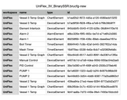
The result is a .csv file which lets you look "under the hood" of any configuration file for Brucontrol. For example, this flow examines the UniFlex_3V_BinarySSR.brucfg which is downloadable from brucontrol.com (or may be included in your recently updated brucontrol app). It returns the file attached. This will give you an accurate idea of where to look for anything missing as well as if you have accidentally implemented naming conventions that get in the way of your scripting.

Beyond that, if you can recover the physical hard drive that crashed (or if you were savant enough to save a backup of default.brucfg somewhere else) and then are able to read it by attaching it to another computer, you can open your last default.brucfg as XML (for example in Visual Studio Code) and find all your scripts by searching on the word "scripts" not only will the name of the script be there, but also the entire script that you can copy and paste into your new brucontrol setup.

While I haven't had time to implement it, it should also be possible to use node-red to detect the wiring map you had for each element by finding the "DevicePort" and then looking under that at the "Number" which will correspond to the brucontrol pin (although this will require alignment through device id or something else.)

I hope this helps someone who has gone through the the frustration of "losing" their work on Brucontrol or having "buggy" behavior in their scripts. It would be nice to have an explanation of how the xml file is set up in the appendix of the manual as well as some sort of reporting tools available from Brucontrol to do this work such as this node-red flow demonstrates. In the meantime, this is one way I can, hopefully, give back to the community.
 

Attachments

  • uniflex_3V.jpg
    uniflex_3V.jpg
    108.9 KB
Gents,
I’m in trouble; installed the very last electric component tonight - I’m planning water tests later this week. This component is a simple float switch. One wire from 5VDC (supply is from VCC pin on my Unishield Mega 2560). The other wire goes into pin 5-3 P on the Unishield, with a 10kohm pull-down to ground. Basically same wiring has my other float switches.

My power is always off when I do my wiring. When I turned power ON; the Unishield is dark!!! I checked the VS input @ 24vdc, the Unishield is grounded, with no other apparent wire issue.

Looks like the Interface (Mega2560) is dead. Any idea on how to confirm before I replace it ( I have a spare)?

I disconnected the float switch completely while I troubleshoot…

I was basically done, I can’t believe it!!’
 
I am making some progress on my troubleshooting; I disconnected the 24vdc input from the Unishield VS pin. I supplied 5VDC from an external power supply into Vin of the Unishield. The power supply function switch is now set at VR Only and…Voilà! I recovered the interface!!!

So it seems like the Unishield DC-DC Power Supply (DDPS) got cooked …, so I need to find the cause and see what is the best way to test the DDPS and hopefully be able to replace it…?
 
Last edited:
I am making some progress on my troubleshooting; I disconnected the 24vdc input from the Unishield VS pin. I supplied 5VDC from an external power supply into Vin of the Unishield. The power supply function switch is now set at VR Only and…Voilà! I recovered the interface!!!

So it seems like the Unishield DC-DC Power Supply (DDPS) got cooked …, so I need to find the cause and see what is the best way to test the DDPS and hopefully be able to replace it…?
So I found the cause of this mishap; the float switch connector at the control panel is shorted…

So the VCC pin from Unishield ended up with excessive amp draw…

So now I need to figure a way to do without the onboard DDPS - perhaps supply all 5VDC directly with my Meanwell 5VDC power supply..?
 
Last edited:
General Arduino Mega2560 query; I have an electronic salon 8 relay board with 5VDC coils; can the relay board’s VCC pin be supplied with a dedicated 5VDC power supply, while the coils get command signal directly from an Arduino digital out pin? Could these command signals draw beyond the recommended 20mA max current?
 
I'd need to see a schematic of the board in question to be sure, but typically the coils are driven via an external power source (Vcc) and control voltage from the arduino is separated. Sometimes there is a jumper involved to share or isolate power.
 
General Arduino Mega2560 query; I have an electronic salon 8 relay board with 5VDC coils; can the relay board’s VCC pin be supplied with a dedicated 5VDC power supply, while the coils get command signal directly from an Arduino digital out pin? Could these command signals draw beyond the recommended 20mA max current?
This is what I got from the d-228 relay board’s data sheet;

Control signal input
High level current
[email protected] 0.4mA@5V 1.1mA@12V 2.2mA@24V
[email protected] 1.0mA@5V 2.4mA@12V 5.0mA@24V

So to answer my own question, the control output from the Mega2560 would be .001 amp, which is below the max amp draw of .020.

Makes sense?
And here’s the schematic…
 

Attachments

  • 77847FC6-27BE-44B9-8328-88C4D5AE2832.png
    77847FC6-27BE-44B9-8328-88C4D5AE2832.png
    1.1 MB
Yes control side you look fine, the one thing that catches my eye on that datasheet is where it says the relay coil operating current at 5V is 720ma. What is not clear is if that is the total current for all 8 relays being actuated at the same time or current draw for a single relay. If its a single relay, you'll need quite a beefy 5v PSU if you intend to fire all 8 (or more) relays simultaneously.

edit: The spec sheet says 720ma "relay all action", so I'm going to interpret that as 720ma total draw of all 8 relays.
720ma total draw is also How I see it
 
Is there a Limit on The Mega (or Grand Central) Unishield related to the number of concurrent Digital Outputs used. I know about the limitations on the VA-VD power banks but I am needing to know about the drivers to the internal relays. There is a limit of 200 ma according to the Arduino specs for total outputs (20 ma per output). How much current does each individual Relay take? I have 21 valves so there are 21 on board relays that will be used at once (I have it set where now where each valve gas either an On Output or a Off Output actives so there will be 21 Digitals outs active all the time (Valve is either On or Off and only draws current when changing so I do take that into consideration as how may are moving at a time per bank. In addition, they have either a Red or Green LED that <= 20 ma that are powered by the VA-VD banks (same circuit as the Valve Control.
 
I am trying to hook up some Valves that are powered on and powered off. They are not reverse polarity but have a Negative and two + leads. I am using a Relay to switch. When the Element is Off, it is fine, but when I turn the Element on, it pulses On then Off fairly rapidly {and the valve is moving slighly with the pulses. When I hook them up to the Mega (or Grand Central), the relay pulses on and off. I have thought it might be the relay but I changed the relay out out. Any ideas?
I found the issue. It was a Meanwell 110v to 12vdc transformer. It pulses with nothing connected when checking the power, I had a little round voltmeter on it that did not pulse. I have removed it from service.
 
Is there a Limit on The Mega (or Grand Central) Unishield related to the number of concurrent Digital Outputs used. I know about the limitations on the VA-VD power banks but I am needing to know about the drivers to the internal relays. There is a limit of 200 ma according to the Arduino specs for total outputs (20 ma per output). How much current does each individual Relay take? I have 21 valves so there are 21 on board relays that will be used at once (I have it set where now where each valve gas either an On Output or a Off Output actives so there will be 21 Digitals outs active all the time (Valve is either On or Off and only draws current when changing so I do take that into consideration as how may are moving at a time per bank. In addition, they have either a Red or Green LED that <= 20 ma that are powered by the VA-VD banks (same circuit as the Valve Control.
Bump
 
CIP valve manifold question: I have my valve manifold sitting underneath my HLT, with silicone hoses leading out to the Mash Tun and Kettle. I clean in place opening and closing ball valves via Brucontrol, so I will need to script that aspect soon.

2 concerns so far; first is the fact that some lines are horizontal and don’t drain very well at the end of CIP process. The second is at the various ball valves’ tri clamp interfaces were some sediments seem to aggregate , and remain trapped after CIP…

1685670373553.jpeg


1685670402830.jpeg


Any suggestion on a perhaps vertical valve manifold design (that could have a bottom drain)?

For the valve tri clamp interface, any idea on how to mitigate?
 

Latest posts

Back
Top