bruce_the_loon
Well-Known Member
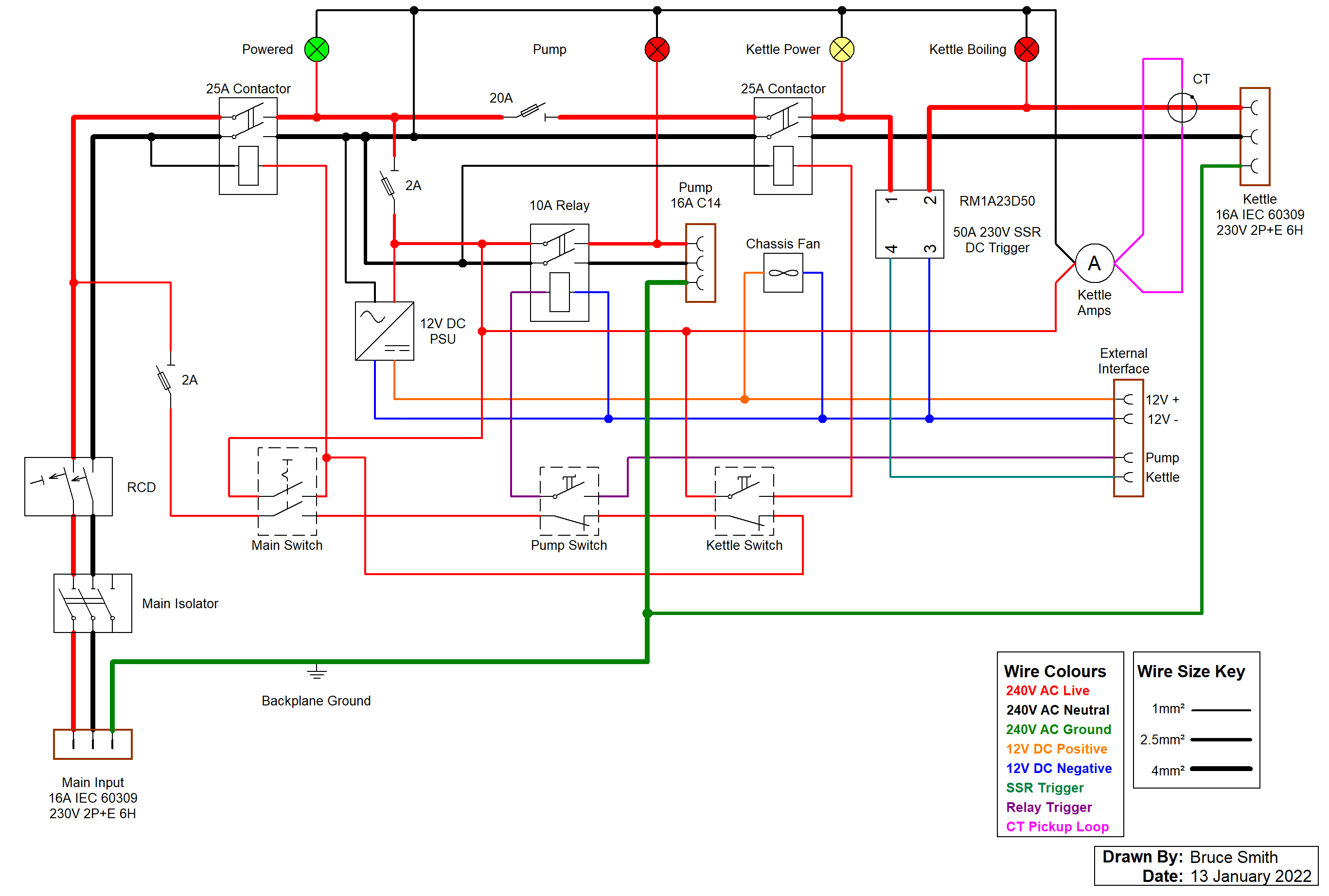
Christmas break turned into a controller panel construction time. Based on a single phase 240V AC design modification to one of doug293cz's circuits with some automation additions. Will try and get the circuit diagram moved from paper to electronic. This will be driving up to a 3500W element which will pull 14.6A at 240V.
The automation additions, relay on the pump specifically, is designed so that I can hook it up to a RPi or similar later on. Debating on whether to get an EZBoil imported or just build something using the RPi and something like CraftBeerPi.

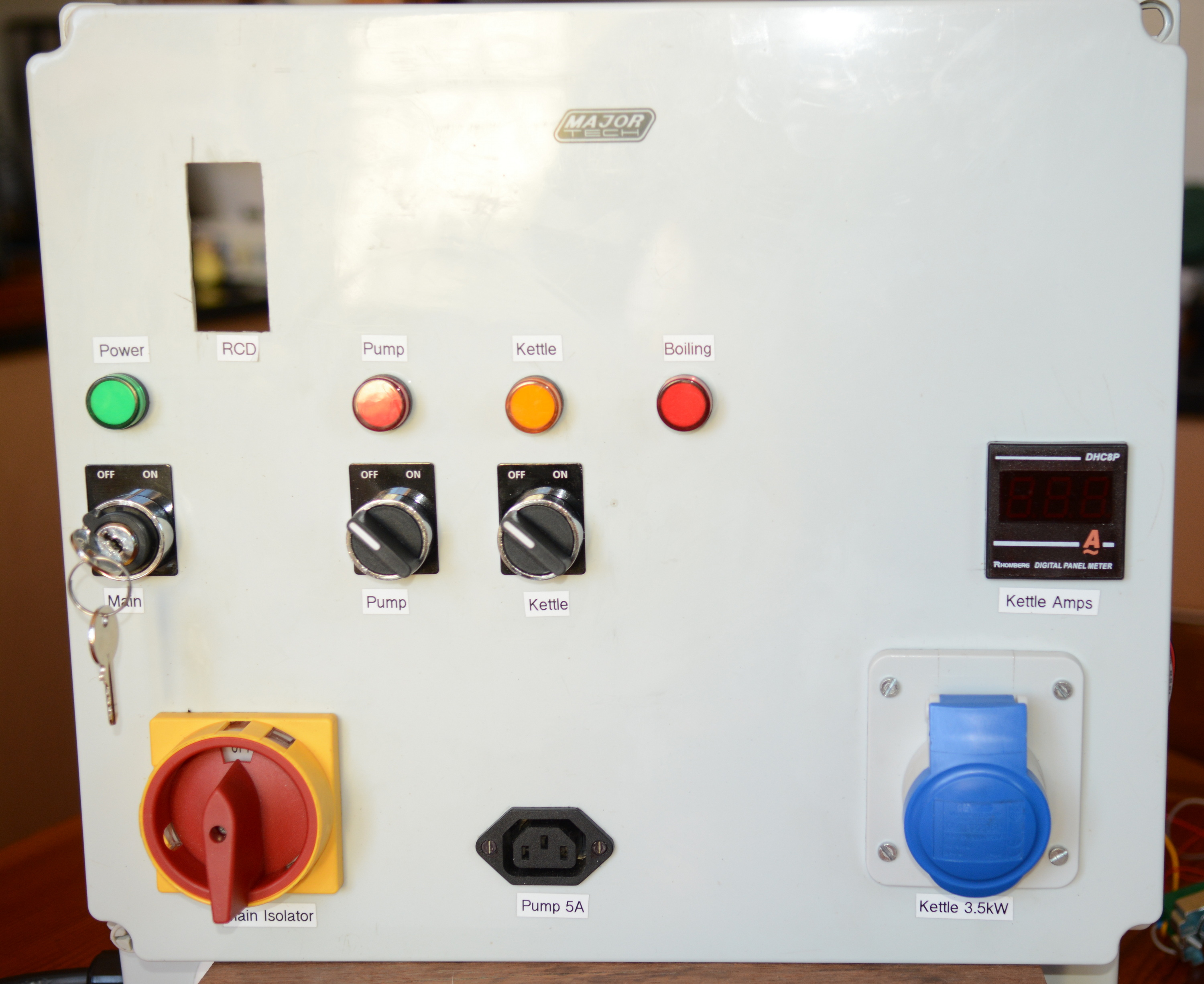
First photo is the front panel including switches, indicator lights, sockets and amperage meter. Isolator is 3 pole 40A rated and the kettle element socket is a 16A IEC 60309 2P+E industrial socket with solid pins. Pump socket is a 16A IEC C13 panel mounted socket. Panel is fed by a dedicated 20A circuit with IEC 60309 socket and plug with 4mm² cabtyre cable.

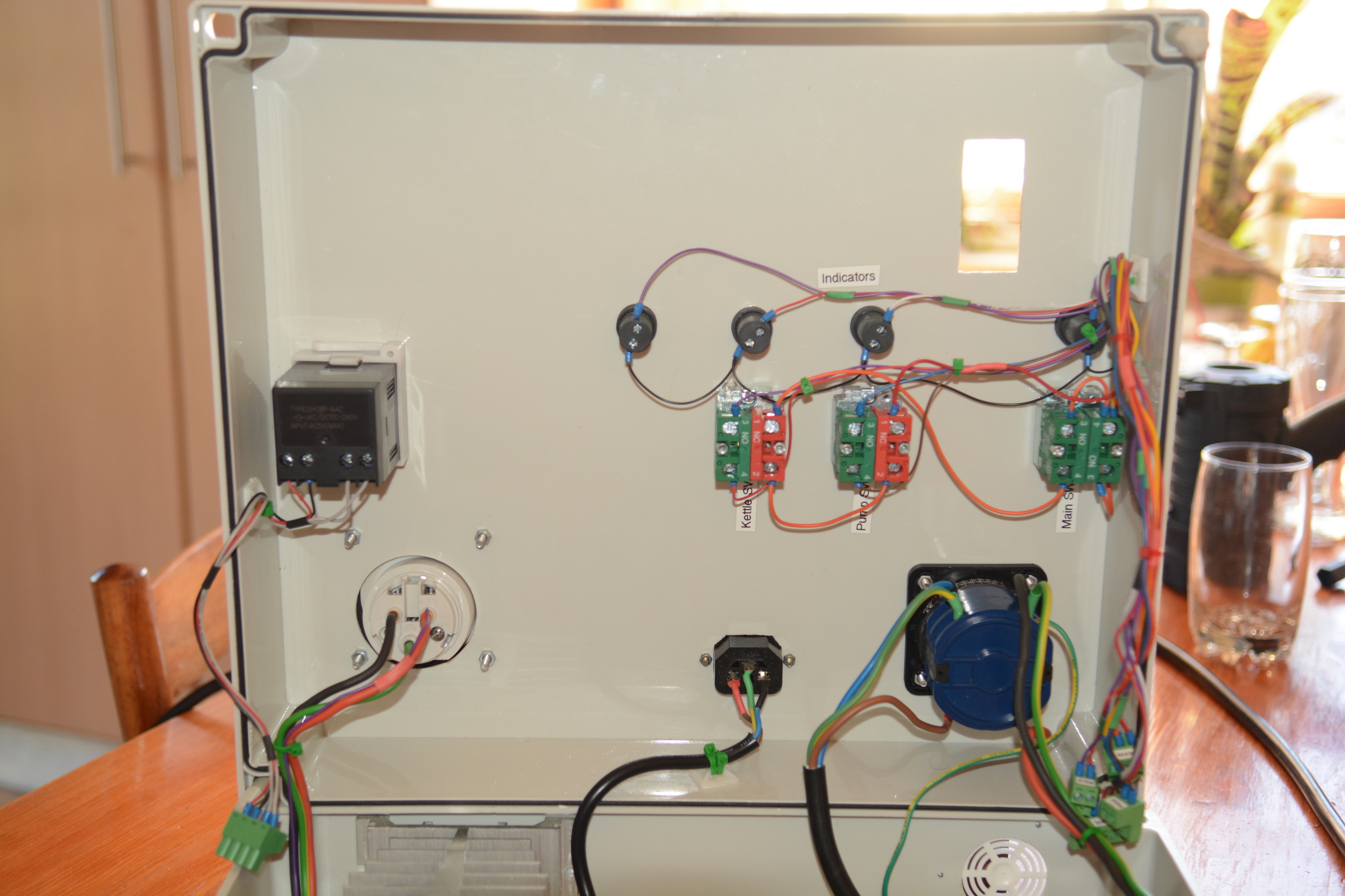
Inside view of the front panel with all the temporary control wiring in place for testing. Waiting for delivery of some plug-in connectors to build the front panel control harness. Primary AC is rigged using 4mm² (12 AWG) flexible wiring for the isolator and socket and 2.5mm² (14 AWG) for the ground line. Pump plug will be wired using 1.5mm² (16 AWG) for all three conductors. The switches are either switching contactors or a DC relay using 0.75mm² (18 AWG) wire. Entire board is 240V AC with 12V DC for some control switching. Indicator lamps are 240V LED panel lamps.

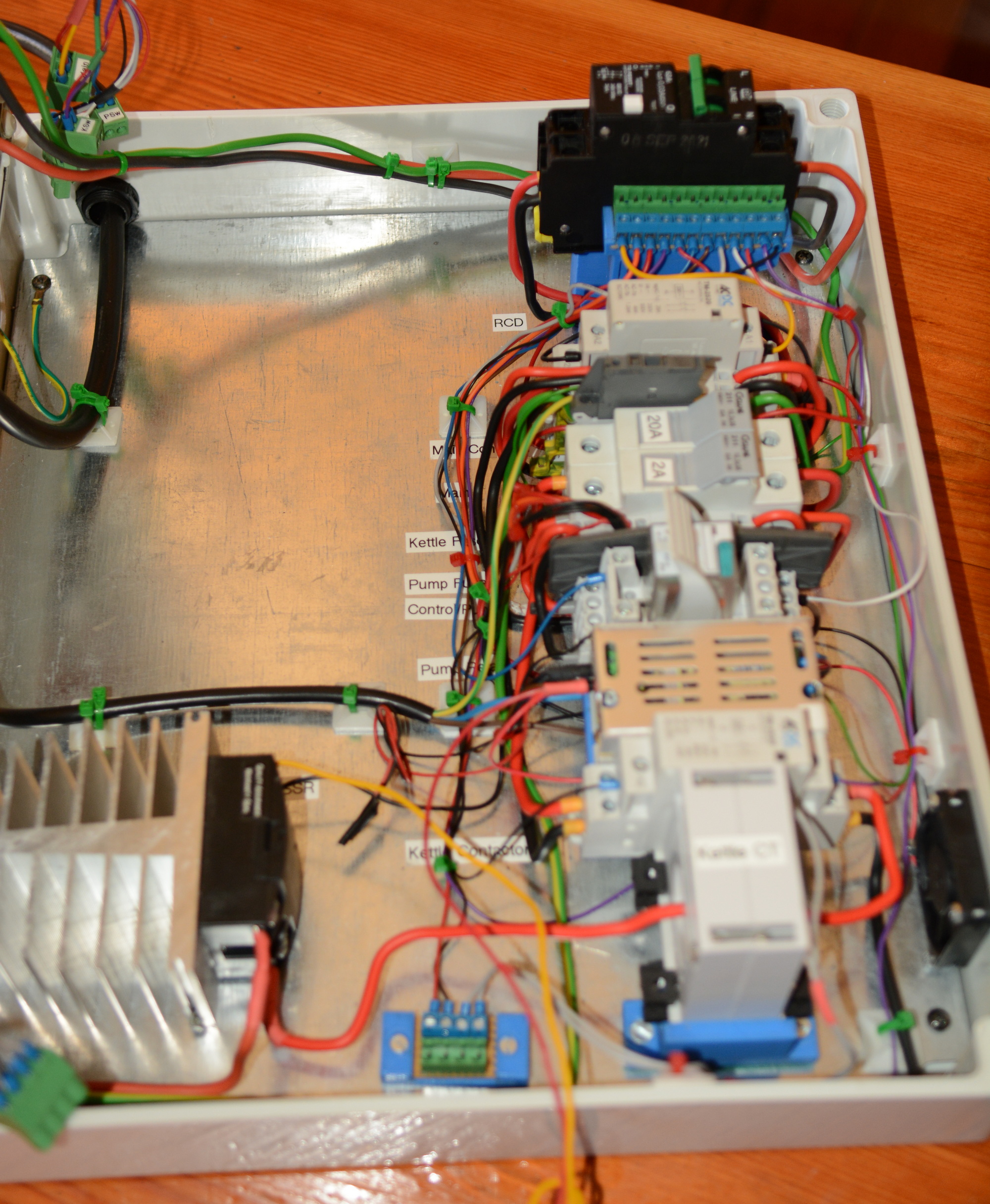
The switch gear and connection system. All DIN rail mounted and wired using 4mm² and 2.5mm² stiff house wire. All screw terminals are using crimped lugs.

Beauty shot of the inside of the panel. Pay no attention to the temporary wiring nightmare. Waiting for delivery on some plug-in screw terminals to assemble the control wiring harnesses to allow for the disconnection of the front panel controls when opening the board.
Tested overnight and the beast is alive and kicking.

The automation additions, relay on the pump specifically, is designed so that I can hook it up to a RPi or similar later on. Debating on whether to get an EZBoil imported or just build something using the RPi and something like CraftBeerPi.

First photo is the front panel including switches, indicator lights, sockets and amperage meter. Isolator is 3 pole 40A rated and the kettle element socket is a 16A IEC 60309 2P+E industrial socket with solid pins. Pump socket is a 16A IEC C13 panel mounted socket. Panel is fed by a dedicated 20A circuit with IEC 60309 socket and plug with 4mm² cabtyre cable.

Inside view of the front panel with all the temporary control wiring in place for testing. Waiting for delivery of some plug-in connectors to build the front panel control harness. Primary AC is rigged using 4mm² (12 AWG) flexible wiring for the isolator and socket and 2.5mm² (14 AWG) for the ground line. Pump plug will be wired using 1.5mm² (16 AWG) for all three conductors. The switches are either switching contactors or a DC relay using 0.75mm² (18 AWG) wire. Entire board is 240V AC with 12V DC for some control switching. Indicator lamps are 240V LED panel lamps.

The switch gear and connection system. All DIN rail mounted and wired using 4mm² and 2.5mm² stiff house wire. All screw terminals are using crimped lugs.
- Starting from the left side with power input from the isolator into a 63A 30mA residual current device as the dedicated feed is not RCD protected at the house board.
- From the RCD, the power is fed through a 25A contactor switched by doug's normally closed pump and element switch protection design.
- From the contactor power is fed to the ABB 4mm² spring connectors for distribution.
- A 4mm² circuit feeds via the 20A fuse to the 25A kettle contactor.
- A 2.5mm² circuit feeds via the 2A fuse to the pump and instrumentation/control devices.
- The kettle live wire feeds from the contactor through a 30A CT to a 50A 240V SSR. Went for way overrating on the SSR, and all the wiring for safety margin and possible future expansion.
- 4mm² flexible wire from the SSR to the IEC 60309 socket along with matching neutral and 2.5mm² earth line.
- The 2A circuit feeds a 12V DC switch mode PSU and a 10A 240V relay for the pump. Live testing of my magnetic pump gives max 0.5A load when pressure-locked.
- The pump switch controls the 12V DC coil on the relay and 2.5mm² wire will run to the IEC C13 socket.

Beauty shot of the inside of the panel. Pay no attention to the temporary wiring nightmare. Waiting for delivery on some plug-in screw terminals to assemble the control wiring harnesses to allow for the disconnection of the front panel controls when opening the board.
Tested overnight and the beast is alive and kicking.


![Craft A Brew - Safale S-04 Dry Yeast - Fermentis - English Ale Dry Yeast - For English and American Ales and Hard Apple Ciders - Ingredients for Home Brewing - Beer Making Supplies - [1 Pack]](https://m.media-amazon.com/images/I/41fVGNh6JfL._SL500_.jpg)


