• Please visit and share your knowledge at our sister communities:
  • If you have not, please join our official Homebrewing Facebook Group!

    Homebrewing Facebook Group

Beginning my EBIAB Brewery Build..

Homebrew Talk

Help Support Homebrew Talk:

This site may earn a commission from merchant affiliate links, including eBay, Amazon, and others.
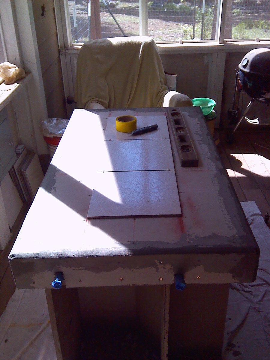
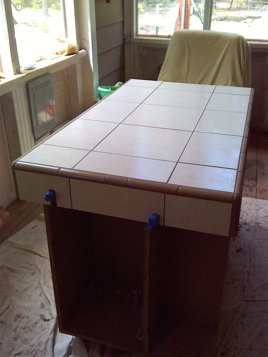
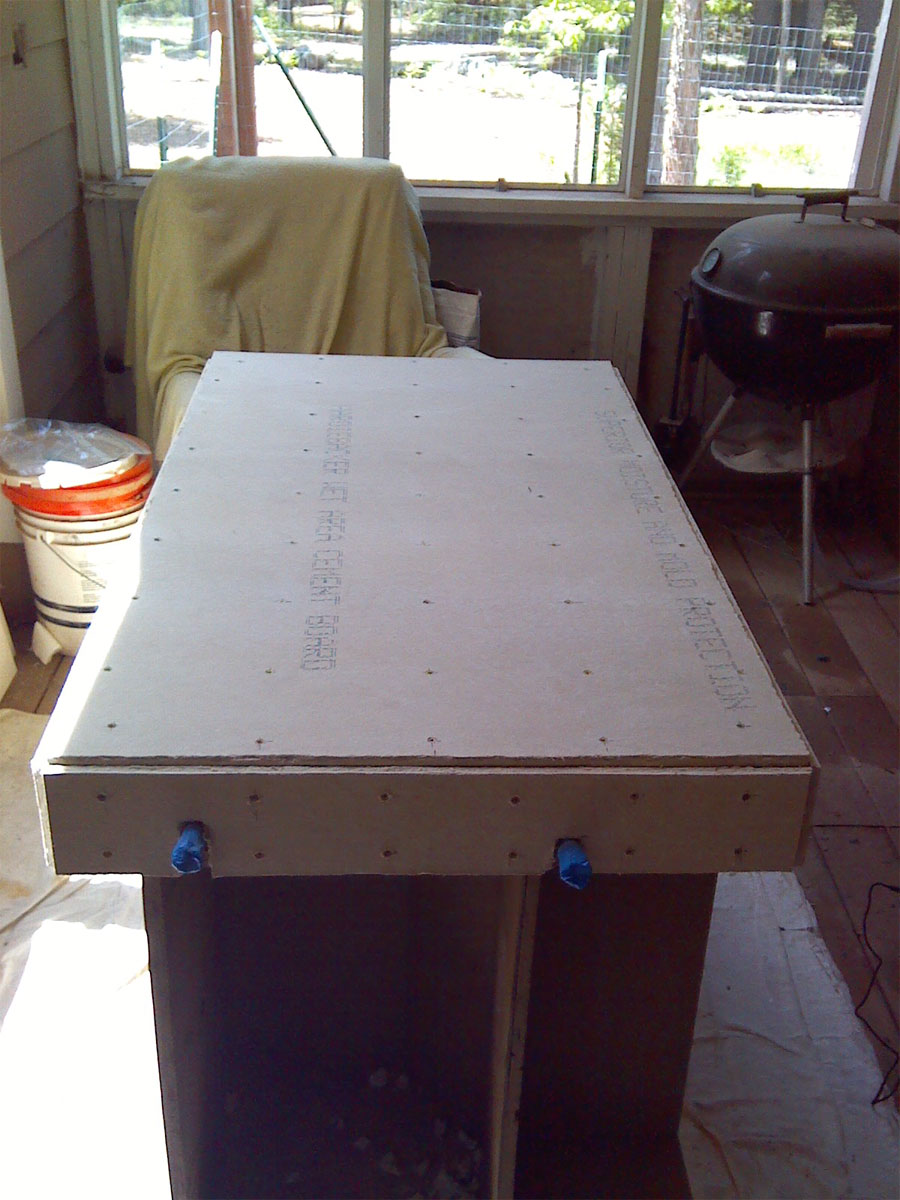
So, Thursday after work, I started tiling the brew stand... Thursday I put in the hardibacker, mortared/reinforced the edges, and set the reference tiles...

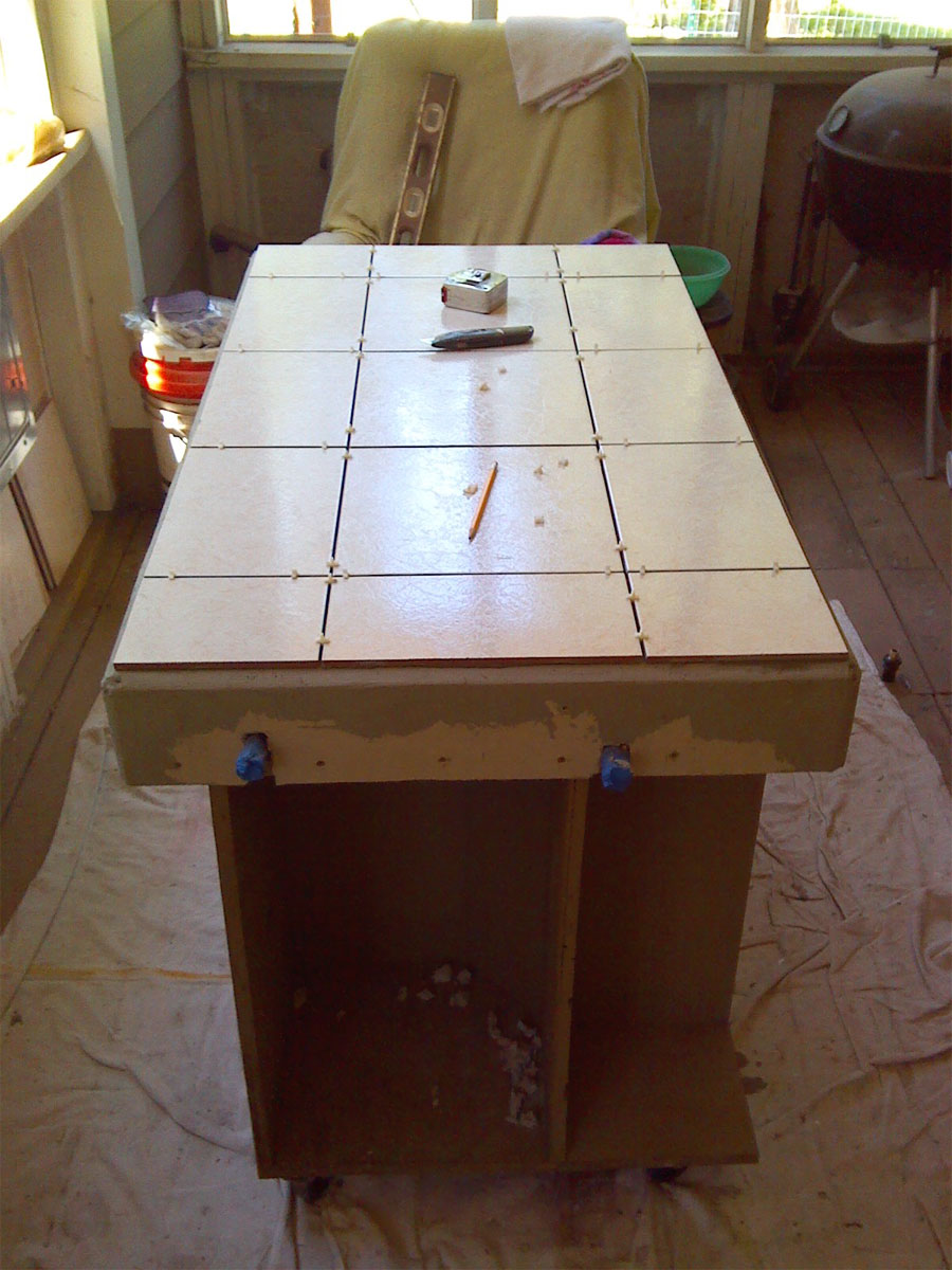
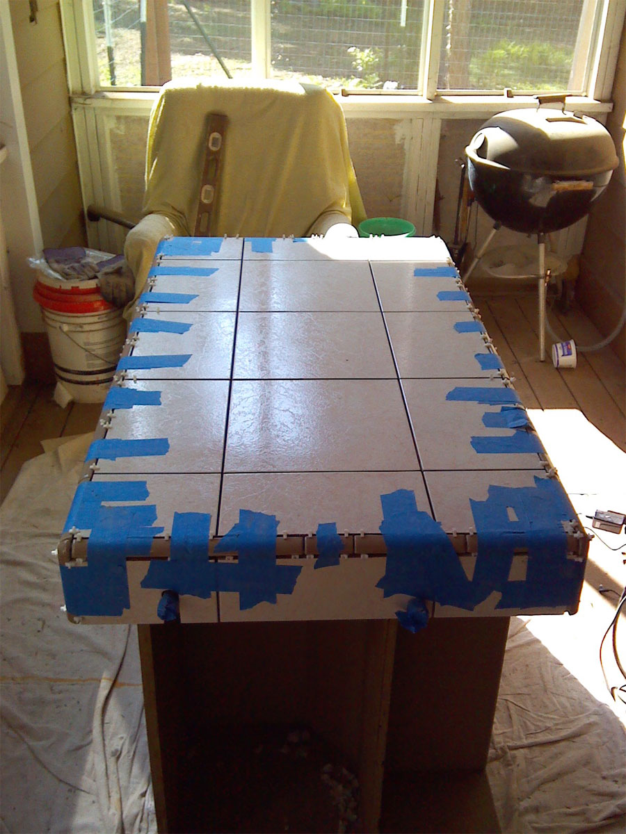
Friday I finished tiling the thing.. Quarter round tile is a PITA to install...

Saturday morning, when I removed the tape, a couple of pieces of the quarter round came loose, so I re-mortared them...

This morning (Sunday), I went into town to exchange the unsanded grout for sanded version, as I had originally planned on having no grout lines, but that plan would have left me running out of quarter round trim...

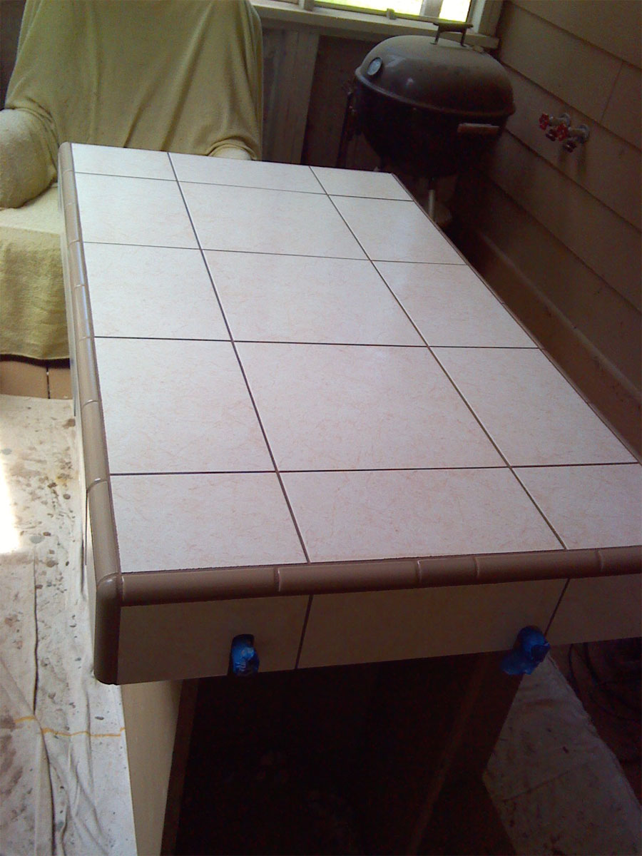
So, then I came back and grouted it in, all before noon.. When the grout dries, it should be the same color as the quarter round...

So, the brew stand is done.... Will seal it in about a month... Next up, I need to run some convenience outlets along the back wall behind the brew stand and the table next to it, and also run a 240v 30a dryer outlet to power the brewery...

Later this week I plan to start on the steel kettle stand/grain crane....

I'm waiting for the enclosure for the electronics to arrive, and other than that I have all the parts to finish this side of the brewery... Will probably brew a couple of batches before I deal with upgrading the fermenter and kegging side later this ummer....

Progress... Glad that part is over... Later on, I'm planning to build a matching table to sit next to it, and a matching end table to use next to a chair...

Time to relax for the rest of the holiday weekend... Smoking a fat Tri-Tip tomorrow... ;)
brew-stand-tiling-001.jpg


brew-stand-tiling-003.jpg
 
Progress!

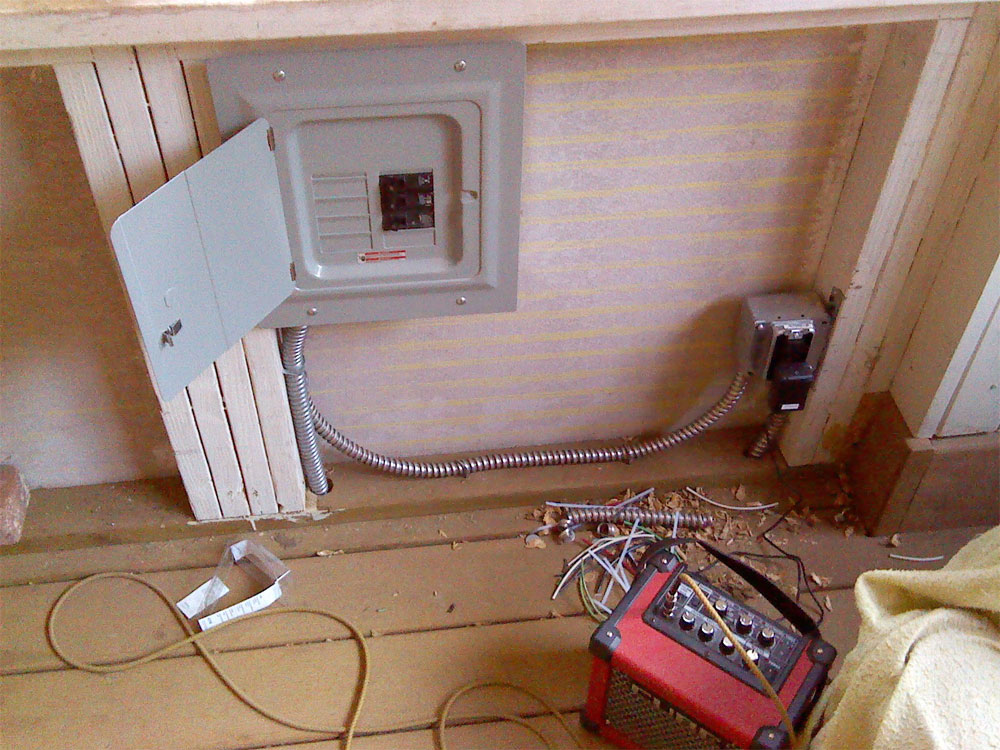
The new panel out on the porch... This is fed by a 50A 2P GFCI breaker located in the emergency power panel in thehouse...

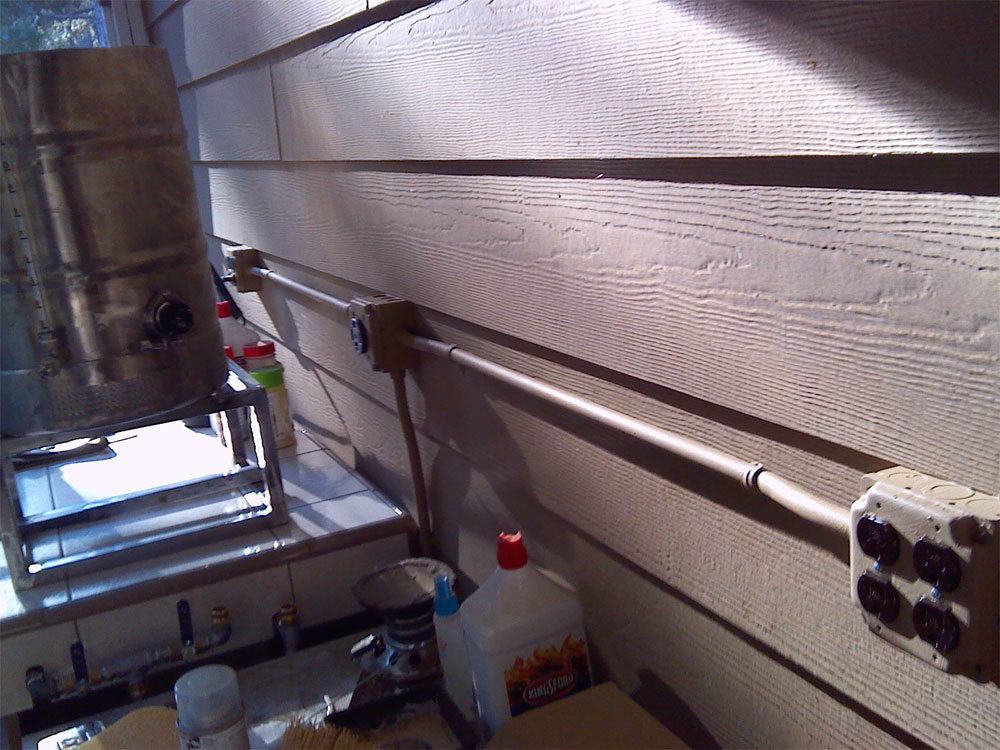
30A 2P breaker will feed the brewery, and 20A 1P breaker feeds that plug next to the panel, as well as two quads for general purpose power along the same wall as the brewery (see th enxt picture)...

Later, this panel will feed several more outlets on the porch, as well as a couple outlets out on the deck, and power out to the picnic/firepit area..

brew-build---electrics-008.jpg
 
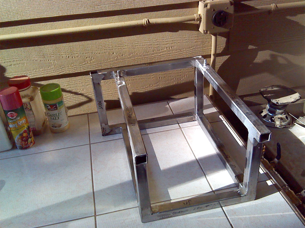
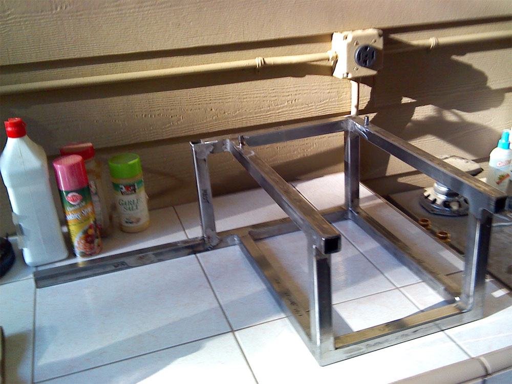
Here's what I spent today doing... Made the brew stand out of 1 x 1 x.109 steel square tube, welded it all up, and ground down all the welds

brew-build---sculpture-001.jpg
 
Here is is with the extension brace installed, this will be necessary to keep the whole shebang from tipping over when the crane swings the basket full of wet spent grains out to set them down next to the kettle after the mash..

I made it removeable, as I'm hoping to be able break everything down and store it in the bottom of the brew cart it's sitting on now...

brew-build---sculpture-002.jpg
 
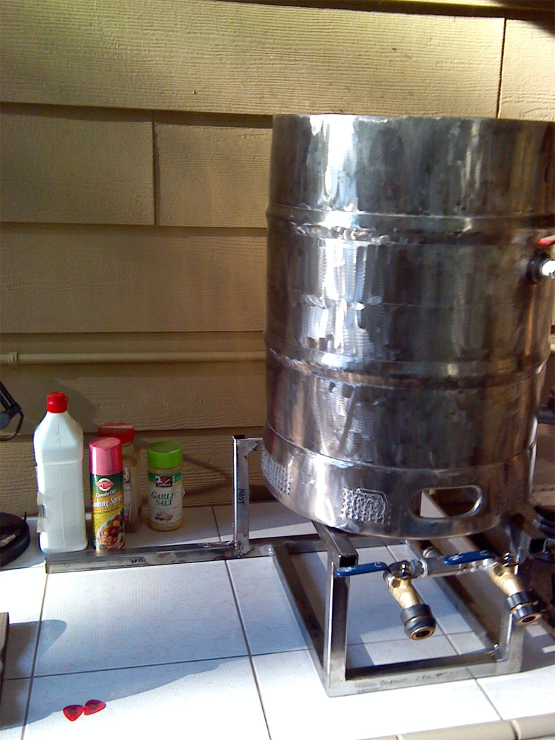
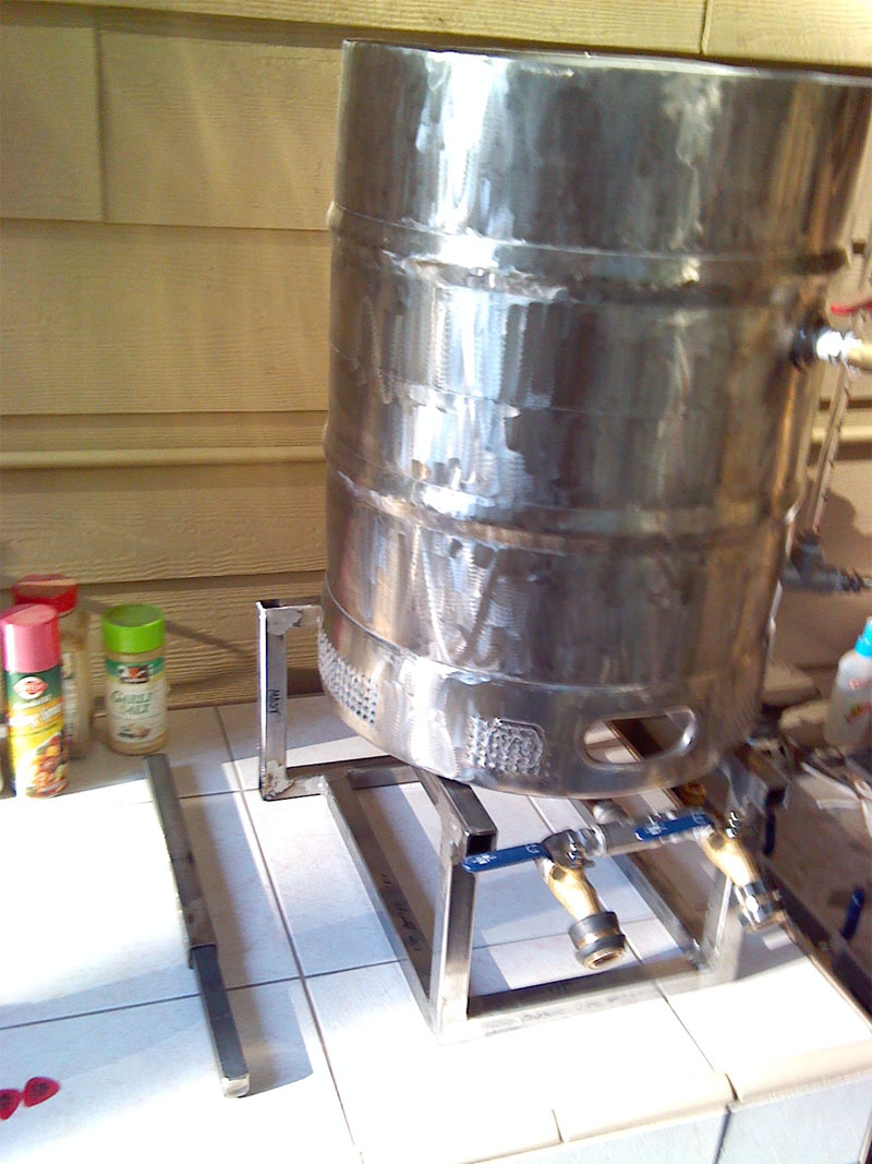
Here it is with the keggle sitting on it...

The mast will install into that square hole just to the left of the keggle (it says mast :; ) and then the swing crane will install on top of that...

I need to order some plastic caps for the ends of those tubes at the front and for the extension brace too...

brew-build---sculpture-005.jpg
 
This shows the 3/4" square steel bar that I welded into the extension.. it slides into the other section as shown in prior pictures...

Now, I gotta build the mast section and the swing crane assembly.. Then I gotta take the flap disk and some sandpaper to everything, paint it, and install the rubber feet on the bottom, and the pulleys and winch on the crane, as well as the bearings on the mast...

The electronics enclosure finally arrived yesterday, so now I can start designing all that, wiring it up, and putting it all in a nice wooden box..

I may have this thing to a point where I can do a basic test of the system... But will still have to build the crane assy, the COFI for the Mash, and finish up the plumbing..

I want to install another 1/2" spud in the keggle too for hooking supply water up the the system....

getting there.. progress...

I'm tried.. That little steel sculpture took all day... out in the hot sun...

brew-build---sculpture-006.jpg
 
Started on the controller today, since work got rained out...

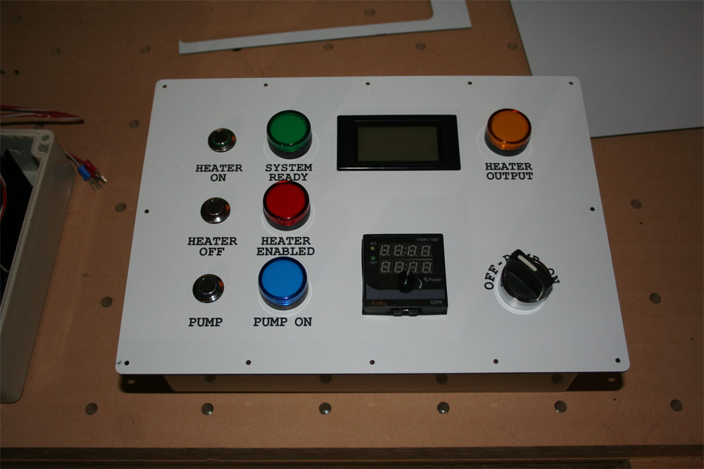
So, I made a panel face for the controller, engraving text and cutting holes in a piece of dual layer/color engraving/label plastic...

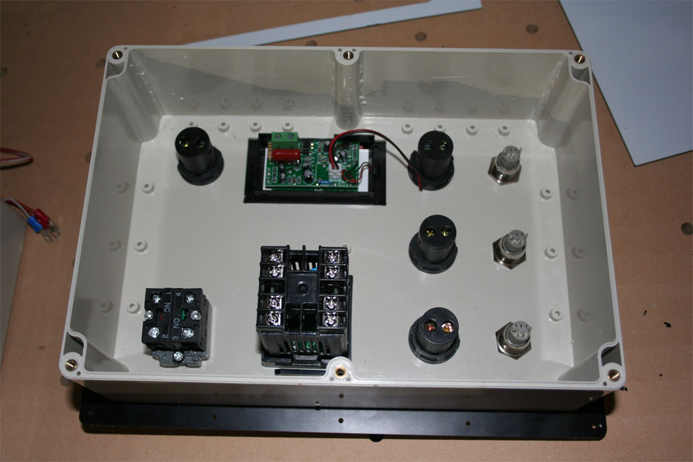
Came out awesome.. Then I took the bottom half of the enclosure I got (finally), which I'm using for the top half, and cut matching holes in it, A larger one for the meter, and installed the boil controller, the meter, the indicators and switches...

Hoping I have to morrow off too, as I'm on a roll and want to keep going.. Want to do the back half where the contactor, heat sink/SSR, relay, plugs, connectors, etc, will all go, so that I can start wiring it up this weekend...

Anyways, here's the user side of the controller and the inside of that half.. Very pleased with how it came out..

brew-build---controller-001.JPG


brew-build---controller-002.JPG
 
and here's the bottom section that I'll be working on next... after that, I wire it up and then build a nice wooden box to mount it all in....

Then I get to do my initial test of the system! Yippee! :ban:

brew-build---controller-003.JPG
 
and here's the bottom section that I'll be working on next... after that, I wire it up and then build a nice wooden box to mount it all in....

Then I get to do my initial test of the system! Yippee! :ban:

Do you really plan to mount the heatsink for the SSR inside the plastic enclosure? If so, that is an extremely poor thermal design. Or, is the position in the photo just temporary for mock up?

Brew on :mug:
 
Do you really plan to mount the heatsink for the SSR inside the plastic enclosure? If so, that is an extremely poor thermal design. Or, is the position in the photo just temporary for mock up?

Brew on :mug:


No, It's just sitting there for layout.. It will be half in and half out... I plan to cut a hole a bit larger than the size of the heat sink in the back of the box, and there will be a piece of 3/4 plywood or MDF on the back of the box through which I can mount some of the parts through the plastic too and also use to support the enclosure in the larger wooden contraption it will all sit in, including space for the cables to store underneath it (probably maple) .. The MDF will have a hole the 'width of the heat sink as well (but taller so that there is plenty of air space around it), and the heat sink will mount to that' sticking up into the box.. IOW, the heat sink tabs will be mounted to the far side of the wood.. Then there will be a small standoff on the mounting ends of the heat sink where another piece of wood or plastic will hold the fan that will blow on the back of the heat sink..

So the heat sink will only be sticking into the box the depth of the SSR, so that there are no electrics exposed, and there will be a fan on the half of the heat sink that is on the outside of the enclosure...

I was going to use the thermal switch that comes with the fan, but now I'm thinking that I'll just have it come on and run whenever the system power is applied...

If that is somehow not enough, I'll just move it a little farther outside the box...
 
Just how hot do these things get anyways? I want to design so that I'm well outside of the margin..

IIRC from the specs, SSR's can dissipate about 35W. How hot they get depends on the thermal path to ambient. The thermal path consists of the interface between the SSR and heatsink, and the the heat transfer from the heatsink to the air. A thin (just thick enough to fill any gaps), void free, layer of heatsink compound minimizes the thermal resistance between the SSR and heatsink. A thicker layer starts to increase the thermal resistance. Larger heatsinks, with more and larger fins, transfer heat more efficiently to the air. Air flow across the fins really boosts the heat transfer from the heatsink to the air.

With poor cooling design, an SSR could get over 180˚F, which could seriously affect it's lifetime. With good design, the SSR should stay under 120˚F, or even lower. The heatsink will be at a lower temp than the active device inside the SSR.

Getting more specific than that for predictions requires complicated measurements and/or modeling. People make careers out of doing those kinds of predictions. You can measure the temp on the heatsink immediately opposite the center of the SSR with an infrared thermometer. If that spot on the heatsink measures less than 120˚F, then you should be ok. You might be ok higher, but shoot for something conservative.

Brew on :mug:
 
So what does that mean as far as my Design?

I will definitely be using heatsink compound (I have quite a bit left over from when I built the CNC) when I switch out this SSR to the Mager.. (This one will be a spare)

I will be brewing outside on the patio on hot summer days where it is typically in the nineties and occasionally over 100.. The heat sink is large, and the bottom half of it will be outside the box in shade, with a fan on it..

I think your design will be ok.

Brew on :mug:
 
So, seeing I got rained out of work yesterday too, I went to work on the bottom section of the controller..

After doing all the layout in CAD, I made a base plate to hold the thing out of 1" MDF and then used the CNC to cut and drill all the holes..

Brew-Control-001.jpg
 
Then after I did that, I machined the piece of MDF itself... This is used to hold the Heat sink half out of the box, where the fan can cool it, to mount the fan, to give the large Romex Connectors a rigid mounting plate so that I don't ever have to worry about them breaking the box as the cables get moved around, and to give something to mount the bottom section to in the wooden box I will be building so that the thin plastic face plate isn't the only thing holding the fairly heavy box in place...

Also, it gives a substantial material to screw all the components on the inside of the box to..

Brew-Control-004.jpg
 
Here is how it sits on the back, showing the pockets for the heat sink and the Romex Connector's mounting plate...

Brew-Control-005.jpg
 
Here is the back side with everything screwed down and all the components inside...

The fan and it's mounting plate are on the right..

Brew-Control-006.jpg
 
This is how the fan will sit on the back.. I have to pick up some rigid plastic tubing to use as standoffs before I can actually mount it...

Brew-Control-009.jpg
 
Here it is with the top section sitting on it..

The whole thing will sit in a nice finished Maple box, held at 30 degrees, with a space underneath to roll up and store the cables (since they are hardwired into the controller)...

Brew-Control-011.jpg
 
Once I get the fan mounted, and the heat shrink I ordered arrives, I can start wiring it up!

If things go well, maybe I can be ready to do my first test next weekend...

:ban:

The chugger I bought was bad, so Bobby sent out a new one, and that one sounds much better... Plumbing is pretty much done... I still have to do some work on the basket, build the wooden box for the controller, build a COFI tube (and figure out how to mount it), design and weld up the crane, and I'll be very close at that point.. Very, very close...

Lots of work yet to do, but I'm through the worst of it... Once I get the crane done, I'll be in the home stretch... Then it's a matter of doing a couple of brews and dealing with any issues I might run into in the brew process... Should all be a breeze after what I went through to build the thing..

Now if ya'll 'scuse me, I need a beer (or three)

:tank:
 
Here is the back side with everything screwed down and all the components inside...

The fan and it's mounting plate are on the right..

I suggest cutting away some of the MDF on the top side to allow airflow to exit from the top side of the heatsink as well as the bottom side. Otherwise the cooling solution looks good.

Brew on :mug:
 
I'm actually thinking of mounting the fan so that it 'pulls' air instead of pushing it.... That way it pulls it from inside the box too...


The gap on the top end is equivalent to a 3/4" hole... I might also drill a couple 3/4 " holes in the side of the box, and put some filter material over them, so that the air is actually going past the top fins too...

If I 'push' air and say I set a glass of beer on top of the box and spill it, I don't want it 'pulling' liquid into the box, but rather 'pushing' it away from it..

In that configuration, I was thinking it would cause 'high speed' air to flow past both sides of the heat sink...


I dunno, I night order a couple extra SSRs just to have on hand in case I screw up and need to reconfigure things a little...

My initial tests will be with just water, just as we're getting into the hot months, and I have a laser temperature meter I can use to watch behavior...
 

Latest posts

Back
Top