• Please visit and share your knowledge at our sister communities:
  • If you have not, please join our official Homebrewing Facebook Group!

    Homebrewing Facebook Group

BCS-460, 3 elements, 2 pumps

Homebrew Talk

Help Support Homebrew Talk:

This site may earn a commission from merchant affiliate links, including eBay, Amazon, and others.
PJ I know you spend allot of time an d effort on the diagrams you provide and I can say they are a god send. I have one more question for you though. What are the parts numbers on the breakers? I think I have found hem because really the diagram only uses two different kinds a 25amp 240volt and a 15amp 120volt..... also wha would be a good contactor from automation direct and would it be ok to mount that on DIN rails or do they need to be mounted in a manor so they will dissipate heat?

Thanks again
Caleb
The DIN rail breakers are:
automationdirect.com - Single Pole - B Curve - 15A 120V - WMZS1B15
automationdirect.com - Double Pole - B Curve - 25A 240V - WMZS2B25
automationdirect.com - DIN Rail - qty 2 - DN-R35S1-2

Regarding the contactors: I've not been able to find suitable contactors on their site. Auber Instruments has contactors that will do the job just fine. auberins.com - Contactor, 2 pole, 30A, 120V Coil
I'm not sure about DIN rail mounting for them.

Hope this helps you.
 
I tried looking for a reasonably priced DIN mountable contactor when I was doing my build, but couldn't find one. I highly recommend "Pioneer Breaker". I bought the majority of my parts from them.
 
The DIN rail breakers are:
automationdirect.com - Single Pole - B Curve - 15A 120V - WMZS1B15
automationdirect.com - Double Pole - B Curve - 25A 240V - WMZS2B25
automationdirect.com - DIN Rail - qty 2 - DN-R35S1-2

Regarding the contactors: I've not been able to find suitable contactors on their site. Auber Instruments has contactors that will do the job just fine. auberins.com - Contactor, 2 pole, 30A, 120V Coil
I'm not sure about DIN rail mounting for them.

Hope this helps you.


PJ you have been a life and money saver. I think through another thread they have located an appropriate coil to replace the ones from Auber but I would like your oppionion on the matter? here is the link... din 120 volt 30A 2 pole

Also I am unsure how to guage the wire on this project would it be best to have a look at the electrical primer provided HERE ?

Thanks again Caleb
 
I first want to let TJ know how everybody on this forum apprecitates how he goes out of his way on diagrahms etc. ....way cool sir! I have a setup that I have been working on for almost 2 years! I call it "Over the Top Brewery" because of the many changes I have made. It is very similar to the op's. The question I have is, and I don't want to come across as a know it all, but why 8 switches on a bcs controlled system, with contactors. I was planning on running an emergency stop that controlled a 50 amp dual pole contactor, of course hooked through a 50 amp gfi in my panel. The bcs would be allowed to monitor temperatures through a 1 amp din mount breaker, even when the contactor is off. I am running din mount double pole breakers through each element. Each element has both legs of 240 going through
ssr's for safety. I thought that the advantage of the BCS was that it was laptop controlled. It seems as though you are "backing up" all of the laptop control with switches and contactors.
 
EDIT After "looking" at the diagrahm, I can see that you are trying to make safeguards in the bcs. By not allowing you to run multiple elements and exceeding the 50 amp limit. But if you are using the bcs as it is intended "aka" process states, I guess the programmer could still screw it up.
 
P-J

I have gathered all the materials for my brewery but I have another question for you concerning the switches Here in the diagram for lets say switch #5-7 I see the two purple contractors at the far right of the diagram and I assume these are the ones on the switch its self(without the red and green attachments). If the given switch is off when in the center position, and in the on position when turned right and on when turned left. How is that represented in the diagram? I am just not sure and I think some time with the continuity setting on my volt meter and studying will help but I was thinking it would be better to just ask the expert first.

Thanks
Caleb :confused:
 
Caleb,

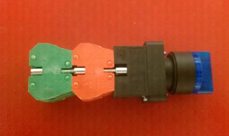
Here is the switch:

m_gcx3264120.jpg


The Red module contains N/C contacts. They cannot be easily used in this particular application. For the wiring diagram the switches need to have N/O modules only. The Switch Lamp connections are located on the switch base module (Black).

And the switch layout:

Switches off-on-off-3.jpg


In the drawing I'm showing each switch section as having 3 terminals. There are actually 4 terminals for each double throw section. The Switch Lamp connections I represent as the red squares on the right side of each unit in the drawing.

I hope this helps.
 
As another issue with this type of switch. The "center off" type of switch has a completely different behavior with N/C contacts than the switch type that is not a center off type. Just saying.

Take a look:

Switches-off-on-off-no-nc-off-1.jpg


Just saying.

I sure hope this helps everyone to understand the complexity of this type of switch module.
I'll shut up now. I'm done...

P-J
 
That's awsome P-J. These things might be a pain in the but to draw out in a diagram but they sure do their job well. I can't imagine what a pain it would be to wire up an industrial controller without these little guys.
 
As another issue with this type of switch. The "center off" type of switch has a completely different behavior with N/C contacts than the switch type that is not a center off type. Just saying.

Take a look:

Switches-off-on-off-no-nc-off-1.jpg


Just saying.

I sure hope this helps everyone to understand the complexity of this type of switch module.
I'll shut up now. I'm done...

P-J

Good Morning PJ,

I have been wiring all of this up and have a question? In the previous slides your schematic here. I noticed and was wondering while looking at switch 5, 6, or 7 when one puts it in manual mode how is contact made back at the ssr or is this normally closed?

Thanks Caleb
 
Good Morning PJ,

I have been wiring all of this up and have a question? In the previous slides your schematic here. I noticed and was wondering while looking at switch 5, 6, or 7 when one puts it in manual mode how is contact made back at the ssr or is this normally closed?

Thanks Caleb
When in manual mode, the SSR is energized by placing +5VDC on the SSR's plus input terminal #3. This triggers the SSR and circumvents the BCS controller function. (i.e. - manual mode)

Hope this helps.
 
Thank you again PJ for you wealth of information but I am still a little daft about the drawing or the switches and the connection to the N/O contactors. On the wiring diagram I see three points of contact (5, 6, 4) for a switch and another three points stacked next to it (2,3,1). Do each one of these section represent the two switch positions of left and right? I am wondering does the +5 volts contact and the out 1 share the same contact? I am very confused on this matter and any help would be useful.

Thanks again

CD
 
Good Afternoon PJ- I have been doing a little more digging and after looking over the schematic again and some of your older schematics I found this thread
Post 74 Could you explain how to use these switches described in the current thread like you did in the linked thread? THank you again for all your hard work.

CD
They would be wired exactly the same way. The difference is that switch is a bat handle switch and the diagram shows an illuminated switch.
 
They would be wired exactly the same way. The difference is that switch is a bat handle switch and the diagram shows an illuminated switch.

OK going back to your original diagram on this thread here the switches here have 2 inputs per side (left right) and plus each layer... I don't see how those connections from the drawing are connected to four points? I only see three wires coming into each layer of the switch?
Thanks Again

cd
 
OK going back to your original diagram on this thread here the switches here have 2 inputs per side (left right) and plus each layer... I don't see how those connections from the drawing are connected to four points? I only see three wires coming into each layer of the switch?
Thanks Again

cd
The explanation is HERE in this thread.
And this POST.

Please keep in mind that I will not redraw the diagram.
 
The explanation is HERE in this thread.
And this POST.

Please keep in mind that I will not redraw the diagram.

Thank you for the help PJ and I understand that you don't have time to redraw this. In this post are points 11 and 13 tied together?

Thanks

CD
 
So how does switch 8 have three positions?

cd
It has 3 positions because it is manufactured that way just like switches 2 through 7. The switch turns to the left and the associated circuit contacts close. In the center position all the N/O contacts are open. Turned to the right position and all the associated contacts close.
 
with the switches PJ has mentioned in this diagram the red contact blocks are N/C and the Green are N/O... is this correct? Which also means I would need to acquire 3 more greens according to the diagram?
 
with the switches PJ has mention in this diagram the red contact blocks are N/C and the Green are N/O... is this correct? Which also means I would need to acquire 3 more greens according to the diagram?
With the 3 position switch (center off) you do not want to have any N/C modules (Unless you really understand the total operation of this type of switch and its function).

All the switch modules should be N/O units on a 3 way - center off switch.
Yes. The green is N/O.

Regarding the modules. Generally, when you order the modules, they are a single unit. You need to order them in pairs to accomplish what you are trying to achieve. The modules sit side by side on the switch stack.

I do not think I'm making any sense in my post. I'm about to give up..!!

Hmmm.. Damn....

Wait - wait: Check this out:

BK-SW2a.jpg


NO/NC Switch Block

Does this help???

P-J
 
Back
Top