Beeskneesbrew
Well-Known Member
Pj will that fit in a keggle....I don't see any measurements.

Here is a link to another site that has a good description of it:Pj will that fit in a keggle....I don't see any measurements.


As another issue with this type of switch. The "center off" type of switch has a completely different behavior with N/C contacts than the switch type that is not a center off type. Just saying.
Take a look:

Just saying.
I sure hope this helps everyone to understand the complexity of this type of switch module.
I'll shut up now. I'm done...
P-J
When in manual mode, the SSR is energized by placing +5VDC on the SSR's plus input terminal #3. This triggers the SSR and circumvents the BCS controller function. (i.e. - manual mode)Good Morning PJ,
I have been wiring all of this up and have a question? In the previous slides your schematic here. I noticed and was wondering while looking at switch 5, 6, or 7 when one puts it in manual mode how is contact made back at the ssr or is this normally closed?
Thanks Caleb
They would be wired exactly the same way. The difference is that switch is a bat handle switch and the diagram shows an illuminated switch.Good Afternoon PJ- I have been doing a little more digging and after looking over the schematic again and some of your older schematics I found this thread
Post 74 Could you explain how to use these switches described in the current thread like you did in the linked thread? THank you again for all your hard work.
CD
They would be wired exactly the same way. The difference is that switch is a bat handle switch and the diagram shows an illuminated switch.
The explanation is HERE in this thread.OK going back to your original diagram on this thread here the switches here have 2 inputs per side (left right) and plus each layer... I don't see how those connections from the drawing are connected to four points? I only see three wires coming into each layer of the switch?
Thanks Again
cd
It has 3 positions because it is manufactured that way just like switches 2 through 7. The switch turns to the left and the associated circuit contacts close. In the center position all the N/O contacts are open. Turned to the right position and all the associated contacts close.So how does switch 8 have three positions?
cd
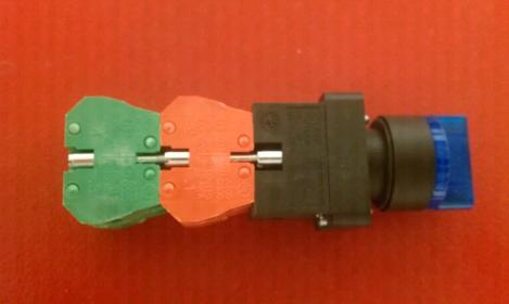
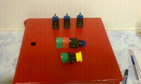
With the 3 position switch (center off) you do not want to have any N/C modules (Unless you really understand the total operation of this type of switch and its function).with the switches PJ has mention in this diagram the red contact blocks are N/C and the Green are N/O... is this correct? Which also means I would need to acquire 3 more greens according to the diagram?


So sorry. I'm not familiar with those switches. (They are illuminated units? No?)I purchased the switches from automation direct. This is what they came with.
Yes, they are the same part number you listed on the diagram.
Ok...If that helps you at all.
Yes. I've already covered the issues regarding these switches in this thread:Will the work for your diagram?
That is correct. For those switches you need another pair of N/O modules added to provide the function needed.But just switches 5-7 correct PJ?