You are using an out of date browser. It may not display this or other websites correctly.
You should upgrade or use an alternative browser.
You should upgrade or use an alternative browser.
Automated/closed system HERMS layout
- Thread starter Elkoe
- Start date

Help Support Homebrew Talk:
This site may earn a commission from merchant affiliate
links, including eBay, Amazon, and others.
Small update, I got some parts today.
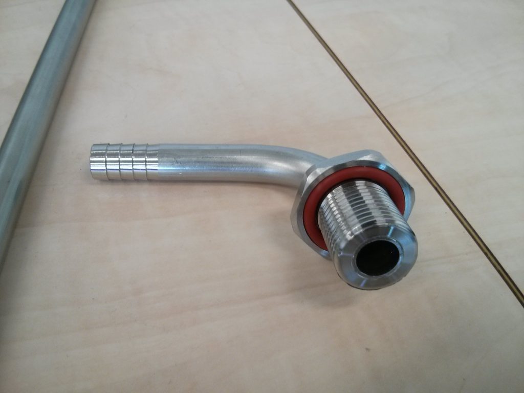
This is our custom designed and CNC'd fitting, with integrated O-ring.
Just put it through your kettle wall, put a locknut on the outside and you have a properly sealed pipe going into the kettle. Should take about 1 minute to install, designed for a 13/16 hole, BSP 1/2" thread.
The O-ring is 1/8 inch and the groove is designed for 20% compression and 20% free groove volume, the proper way for a good seal and a healthy O-ring.
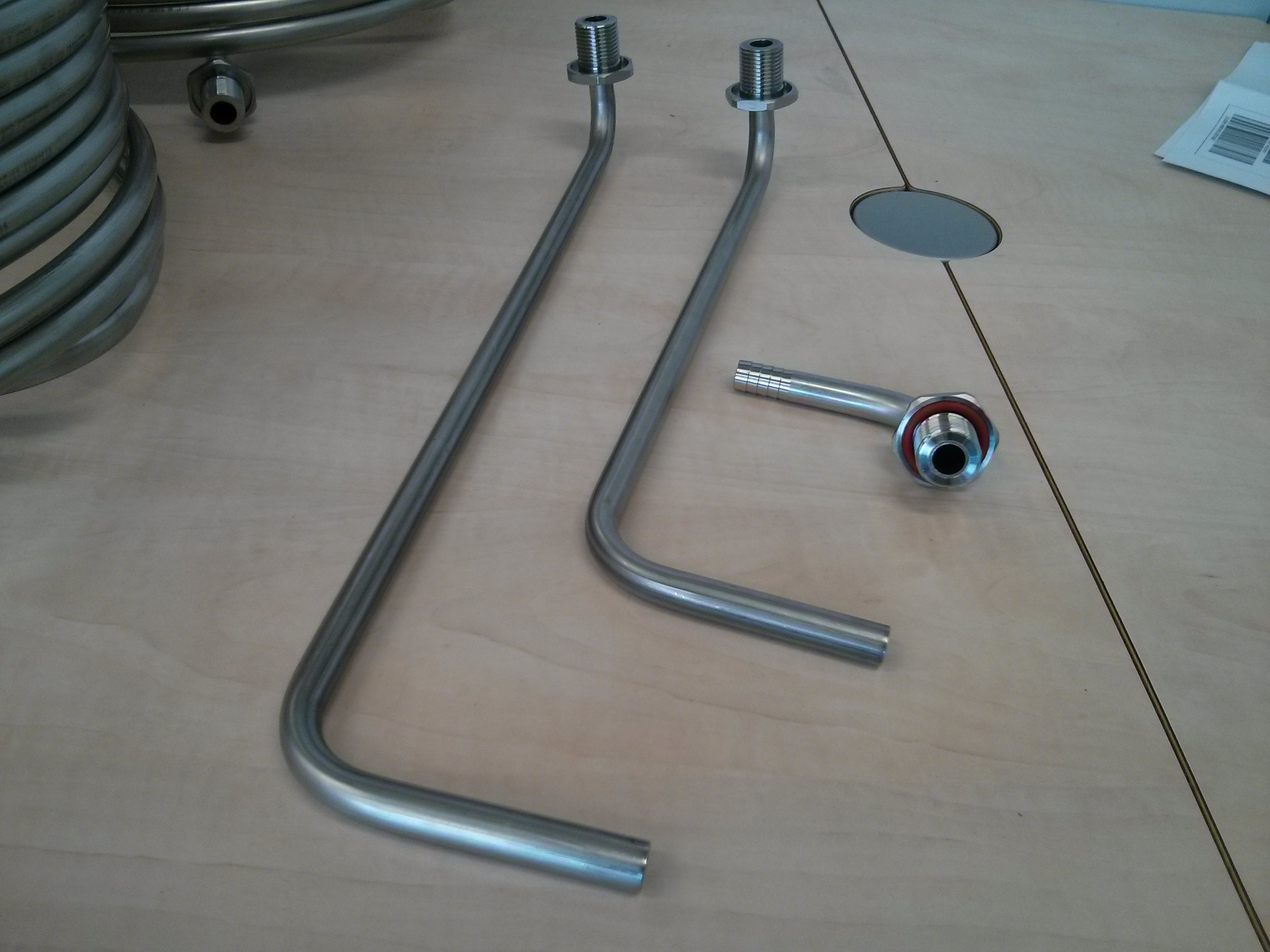
The pipes are hydraulically press fitted onto the fittings, which have a small grove on the inside.
These short pieces can be used as inlet in the mash tun (with silicone hose), HLT inlet or as dip tube.

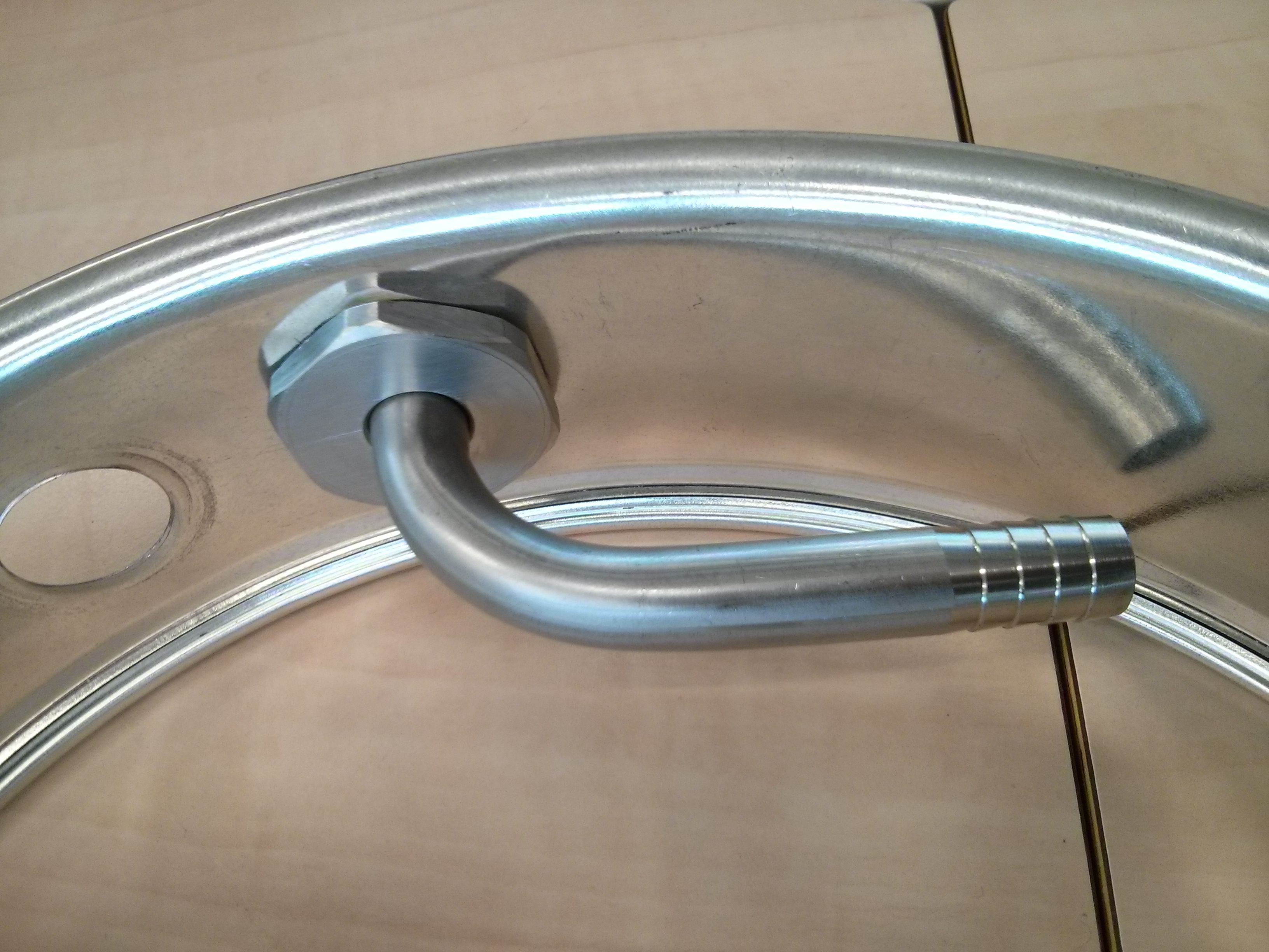
I have not drilled the kettles yet, so here is the fitting in our test kettle (an aluminum spring form).
We designed parts for a 35cm and a 45 cm kettle.
We made 2 coils (30cm and 40cm, both 12 windings):
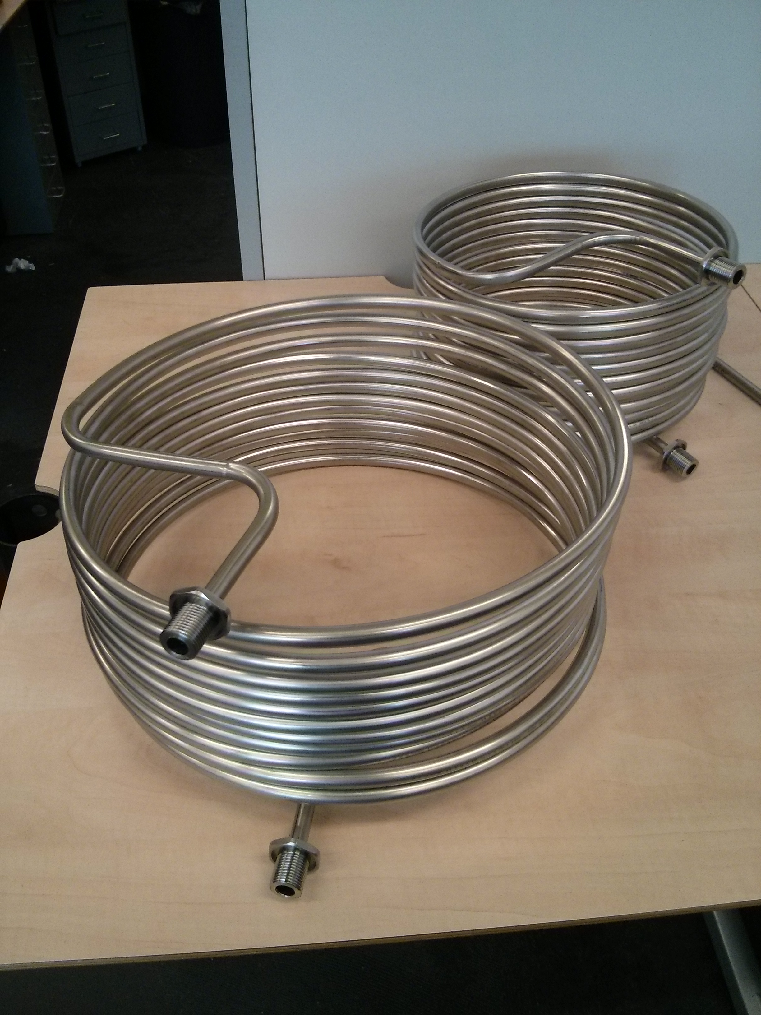
These prototype coils are a bit rough, as the company making them did not have all the tools to bend the radii required. They will develop some custom tooling to make the next prototype perfect. The bends will be done with a bigger radius for a nicer looking coil and better flow.
And finally, we made whirlpool inlets:
I'll post again when we install these in the kettles, still waiting on some parts.
This is our custom designed and CNC'd fitting, with integrated O-ring.
Just put it through your kettle wall, put a locknut on the outside and you have a properly sealed pipe going into the kettle. Should take about 1 minute to install, designed for a 13/16 hole, BSP 1/2" thread.
The O-ring is 1/8 inch and the groove is designed for 20% compression and 20% free groove volume, the proper way for a good seal and a healthy O-ring.
The pipes are hydraulically press fitted onto the fittings, which have a small grove on the inside.
These short pieces can be used as inlet in the mash tun (with silicone hose), HLT inlet or as dip tube.
I have not drilled the kettles yet, so here is the fitting in our test kettle (an aluminum spring form).
We designed parts for a 35cm and a 45 cm kettle.
We made 2 coils (30cm and 40cm, both 12 windings):
These prototype coils are a bit rough, as the company making them did not have all the tools to bend the radii required. They will develop some custom tooling to make the next prototype perfect. The bends will be done with a bigger radius for a nicer looking coil and better flow.
And finally, we made whirlpool inlets:
I'll post again when we install these in the kettles, still waiting on some parts.
Wow.
Something truly huge is happening here.
Cheers!
Something truly huge is happening here.
Cheers!
wbarber69
Well-Known Member
- Joined
- Oct 13, 2013
- Messages
- 2,191
- Reaction score
- 263
I'm gonna start getting elco to fab me up some parts. In the u.s. there is this great new trend among new homeowners with money where they find the most lavish kitchen and bath parts for sinks and tubs and such through these custom bath/tile and granite distributors. Neither of which realize that anything with bsp threads is a waste of money, since it's unrepairable and doesn't mate up with anything else used. Making it pretty difficult to even install in the first place. We usually end up having to pretend we used the parts they bought and have to source cheaper look-alike replacements that actually mate up with standard drain parts.
wbarber69, I choose BSP because it is the standard everywhere except the US.
Most of these parts will be pretty heavy, so shipping to the US could get expensive. I'll probably make an NPT version later and find a US distributor to reduce shipping cost.
Most of these parts will be pretty heavy, so shipping to the US could get expensive. I'll probably make an NPT version later and find a US distributor to reduce shipping cost.


$10.99 ($31.16 / Ounce)
Hornindal Kveik Yeast for Homebrewing - Mead, Cider, Wine, Beer - 10g Packet - Saccharomyces Cerevisiae - Sold by Shadowhive.com
Shadowhive


$58.16
HUIZHUGS Brewing Equipment Keg Ball Lock Faucet 30cm Reinforced Silicone Hose Secondary Fermentation Homebrew Kegging Brewing Equipment
xiangshuizhenzhanglingfengshop

$20.94
$29.99
The Brew Your Own Big Book of Clone Recipes: Featuring 300 Homebrew Recipes from Your Favorite Breweries
Amazon.com


$176.97
1pc Commercial Keg Manifold 2" Tri Clamp,Ball Lock Tapping Head,Pressure Gauge/Adjustable PRV for Kegging,Fermentation Control
hanhanbaihuoxiaoshoudian


$7.79 ($7.79 / Count)
Craft A Brew - LalBrew Voss™ - Kveik Ale Yeast - For Craft Lagers - Ingredients for Home Brewing - Beer Making Supplies - (1 Pack)
Craft a Brew


![Craft A Brew - Safale BE-256 Yeast - Fermentis - Belgian Ale Dry Yeast - For Belgian & Strong Ales - Ingredients for Home Brewing - Beer Making Supplies - [3 Pack]](https://m.media-amazon.com/images/I/51bcKEwQmWL._SL500_.jpg)


$479.00
$559.00
EdgeStar KC1000SS Craft Brew Kegerator for 1/6 Barrel and Cornelius Kegs
Amazon.com


$22.00 ($623.23 / Ounce)
AMZLMPKNTW Ball Lock Sample Faucet 30cm Reinforced Silicone Hose Secondary Fermentation Homebrew Kegging joyful
无为中南商贸有限公司


$53.24
1pc Hose Barb/MFL 1.5" Tri Clamp to Ball Lock Post Liquid Gas Homebrew Kegging Fermentation Parts Brewer Hardware SUS304(Liquid MFL)
yunchengshiyanhuqucuichendianzishangwuyouxiangongsi


$33.99 ($17.00 / Count)
$41.99 ($21.00 / Count)
2 Pack 1 Gallon Large Fermentation Jars with 3 Airlocks and 2 SCREW Lids(100% Airtight Heavy Duty Lid w Silicone) - Wide Mouth Glass Jars w Scale Mark - Pickle Jars for Sauerkraut, Sourdough Starter
Qianfenie Direct


$53.24
1pc Hose Barb/MFL 1.5" Tri Clamp to Ball Lock Post Liquid Gas Homebrew Kegging Fermentation Parts Brewer Hardware SUS304(Liquid Hose Barb)
Guangshui Weilu You Trading Co., Ltd


mmmooretx
HopHead
I will be tracking this thread. I have an up and running Osccys DX1 system, but they are stopping support. I will try and find my Visio/PDF layout (2 pumps, 6 temprature sensors, 6 2 way valves and one 3 way valve). All pot connections have ball valves, volume flow control, and my dump valve is manual. I have never done a full automated run (valve control) and have done manual switch control. I have a 50 foot 1/2 inch stainless heat exchanger in the HLT, all 20 gallon Blichmann pots, and have a temp. probe on the HEX return plus a temp probe in the grain bed (MLT). Other sensors is incoming water temp (Houston summer water can getup to 82F) and one on the output of my plate chiller. I am adding a second plate chiller so I will have one on tap water and one on ice water (ice chest with sump pump).
I will follow Elco's updates closely as I am extremely pleased with his BrewPi.
Update: I tried uploading my Visio layout converted to PDF, but it is 12K and am not sure how to resize to the 700X700 limit of this site. Diagram was built around tabloid size paper (11X17).
I will follow Elco's updates closely as I am extremely pleased with his BrewPi.
Update: I tried uploading my Visio layout converted to PDF, but it is 12K and am not sure how to resize to the 700X700 limit of this site. Diagram was built around tabloid size paper (11X17).
aubiecat
Well-Known Member
Elkoe I like the work you've done on the BrewPi system and what you are doing here.
Can this automated herms system be "dumbed down" to run an electric BIAB system?
Can this automated herms system be "dumbed down" to run an electric BIAB system?
Elkoe I like the work you've done on the BrewPi system and what you are doing here.
Can this automated herms system be "dumbed down" to run an electric BIAB system?
Yes, definitely. We plan to make the system very modular. You can start with a simple BIAB system and add more hardware later, without having to redo your control panel. The system will grow with the brewer
")
You should be able to go from BIAB to HERMS to fully automated HERMS without throwing out any hardware.
wbarber69
Well-Known Member
- Joined
- Oct 13, 2013
- Messages
- 2,191
- Reaction score
- 263
Dude I can't wait. I'm blowing SSRs right now because my panel is so stuffed I can barely get the air to move. I would love to pull the pids out and do away with them. Or save my panel for mobile brewing. All I'll have to do when the day comes is trade out my RTDs for thermowells and I'm ready to go.
mmmooretx
HopHead
Elkoe, any estimate on release date?
I admittedly did not read through the entire thread in detail, but I have some input - sorry if it has already been said. For what it is worth - I use a brewpi setup on both a fermentation fridge and chest freezer... It's awesome.
My HERMS system does not play nicely with an Auberins PIDs as is. It takes a good 30 minutes to hit 'steady state' normally, first off (which is a physical limitation, really). Secondly, depending on pump flow rate, at steady state, the temp differences between the HLT and mash tun may vary 1F... or 7F. I'd be more than happy to explain my system in a bit more detail to you if you want sometime. The large issue comes when you want your mash to hit 155F, for example, and after doughing in you find you are at 148F. To prevent a sweet stout tasting as dry as an IPA, you immediately need to crank you HLT up to 165F and be careful to not overshoot the value - it's extremely difficult. What I've come to realize is that the mash tun and HLT are just such large thermal masses (which is losing heat), it takes a much longer time to change the temperature than I'd expect. Finding the differential part of that PID to keep the algorithm 'fast' is difficult.
I'd recommend keeping the following in mind:
1.) When you are losing a lot of heat in the lines, through the MLT and HLT... Your controls have to 'work harder' to overcome this temperature difference. Its especially difficult when you consider this changes with the current pump flow rate.
2.) To help with #1, I'd reconsider using only silicone lines. I plan on using hard SS plumbing on my brew stand (once I make it) with three way valves and some 'silicone jumpers'. Hard plumbing can be heavily insulated and cleaned easily with a long brush if needed. Plus, its one less thing flopping around that will need replaced over time.
3.) CIP stuff is great, but nothing beats an easily accessible way to brush it out once every few brews. I run plenty of PBW through my system. If it's a large system, I'd recommend some DIY PBW - you'll drive yourself bankrupt if not, haha. The DIY stuff is cheap enough you don't have to worry about it. I've looked at some of my fittings I've taken apart - even with frequent PBW recirculating through it... They still needed a good scrubbing. That being said, solid plumbing can have a T at the end of it, with the end plugged under normal use, but easily removed to snake out the plumbing once in a blue moon.
4.) Really consider how to keep things insulated (HLT, MLT, and lines). I would say some closed cell foam is your best bet if going electric. The reflectex stuff works, but its really intended for radiant stuff (as you probably know). Insulating everything is going to make your controls way easier, especially if you are going to be troubleshooting them for a while.
5.) Consider some nice ways to monitor flow rates. You are probably going to have to, I have a feeling. With a chugger under my keggle MLT (with a bottom drain), I have to keep my pump throttled back a good bit. A nicer false bottom may help, but keep in mind that not all people can run their pump at full bore. It's amazing the difference this makes on the temps. I am not a fan of any 'direct measuring' devices that I'd want in a brewery - cleaning and reliability would be tough. I would consider using two pressure sensors around a fixed pipe bend (we use this method for measuring flow in nuke plants, for what its worth).
6.) I may have missed it, but did you sketch out where your key control input/output will be? Any temp sensor locations? I am curious as to your ideas on it. I've frequently thought that there is some merit to having both a mash tun input/output temp sensor to help with the differential input.
I will keep an eye on this!
wbarber69
Well-Known Member
- Joined
- Oct 13, 2013
- Messages
- 2,191
- Reaction score
- 263
Heide264 I used to have a similar problem with my HERMS setup and regular pids. One thing I did to fix the strike in issue was to use the HERMS coil to heat strike water in the mlt prior to dough in. This allows the mlt to warm up and balance out with the strike water. I find as long as I have the amount of water the recipe calls for plus the amout lost to the false bottom when I strike in I rarely undershoot my dough in temps anymore. I'm sort of right there with you with the long step times, although it doesn't take me 30 minutes, it's pretty close to 20. I don't see where this is a problem, unless you rely on beersmith to run your clock. Then I find I just need to pause it and let my system catch up. I'm sure I could have avoided all this if I had been able to afford a 50' coil instead of opting for a 25' one instead.
Just got started reading on this post! I'm excited to see the outcome of the software and setup!
Just pooped my self out of excitement!
Just pooped my self out of excitement!
TMI
Cheers!
Cheers!
Elkoe, any estimate on release date?
I am trying hard to be ready in time for Christmas.
My HERMS system does not play nicely with an Auberins PIDs as is. It takes a good 30 minutes to hit 'steady state' normally, first off (which is a physical limitation, really). Secondly, depending on pump flow rate, at steady state, the temp differences between the HLT and mash tun may vary 1F... or 7F. I'd be more than happy to explain my system in a bit more detail to you if you want sometime. The large issue comes when you want your mash to hit 155F, for example, and after doughing in you find you are at 148F. To prevent a sweet stout tasting as dry as an IPA, you immediately need to crank you HLT up to 165F and be careful to not overshoot the value - it's extremely difficult. What I've come to realize is that the mash tun and HLT are just such large thermal masses (which is losing heat), it takes a much longer time to change the temperature than I'd expect. Finding the differential part of that PID to keep the algorithm 'fast' is difficult.
I used a hacky mod of BrewPi's fridge algorithm for my first test.
I don't want to use PID for the HERMS eventually, but a model based controller. There is no reason the controller should not know:
- The volume in each kettle
- How they exchange heat
- How much heat they loose
- How much heat is lost in the lines between them
- and much more
For example: say I have a first mash step at 55C and I am mashing 15L. I have 50L in the HLT. The second mash step is at 67C.
If the controller is smart enough it should know that:
Heating the mash 12 degrees takes 4.2 kJ per liter per degree * 15 L * 12C = 756 kJ.
1 degree difference in the HLT stores 50*4.2KJ = 210 kJ. So if I preheat the HLT to 67 + 756/210 = 71C, it will balance out at 67C for both when I start pumping. Of course the controller should also take into account the limits caused by enzyme regions. Beta-amylase denatures above 70C, so the controller should limit the HLT to 70C instead of 71C.
This should be part of the model.I'd recommend keeping the following in mind:
1.) When you are losing a lot of heat in the lines, through the MLT and HLT... Your controls have to 'work harder' to overcome this temperature difference. Its especially difficult when you consider this changes with the current pump flow rate.
I am using silicone lines everywhere. I like to see the beer flow, it is easy to install and with camlocks on each hose, easy to clean too. IT is also very cheap to replace if they go bad.2.) To help with #1, I'd reconsider using only silicone lines. I plan on using hard SS plumbing on my brew stand (once I make it) with three way valves and some 'silicone jumpers'. Hard plumbing can be heavily insulated and cleaned easily with a long brush if needed. Plus, its one less thing flopping around that will need replaced over time.
I think the silicone will make the system easy to take apart and it will be easy to see if gunk builds up.3.) CIP stuff is great, but nothing beats an easily accessible way to brush it out once every few brews. I run plenty of PBW through my system. If it's a large system, I'd recommend some DIY PBW - you'll drive yourself bankrupt if not, haha. The DIY stuff is cheap enough you don't have to worry about it. I've looked at some of my fittings I've taken apart - even with frequent PBW recirculating through it... They still needed a good scrubbing. That being said, solid plumbing can have a T at the end of it, with the end plugged under normal use, but easily removed to snake out the plumbing once in a blue moon.
I am considering isolating the mash tun for a more even temperature distribution, but I'll do some more testing unisolated first.4.) Really consider how to keep things insulated (HLT, MLT, and lines). I would say some closed cell foam is your best bet if going electric. The reflectex stuff works, but its really intended for radiant stuff (as you probably know). Insulating everything is going to make your controls way easier, especially if you are going to be troubleshooting them for a while.
I will get a sample of 12V pumps with a 0-5 speed control signal. I am going to use pressure based volume sensors in the kettles, which should help me calibrate the flow rate. I am interested in the flow rate sensor you describe. Where can I find more info to build one?5.) Consider some nice ways to monitor flow rates. You are probably going to have to, I have a feeling. With a chugger under my keggle MLT (with a bottom drain), I have to keep my pump throttled back a good bit. A nicer false bottom may help, but keep in mind that not all people can run their pump at full bore. It's amazing the difference this makes on the temps. I am not a fan of any 'direct measuring' devices that I'd want in a brewery - cleaning and reliability would be tough. I would consider using two pressure sensors around a fixed pipe bend (we use this method for measuring flow in nuke plants, for what its worth).
In our first test, we found that there was a temp difference between the mash and in front of the pump of 2 degrees. This is probably because of the big block of fittings that the temp sensor was mounted in. I am going to try using only flow temp sensors at mash tun out, mash tun in, htl out, boil in, boil out. By mounting the sensors at kettle out, they should be a good representation of the kettle temp.6.) I may have missed it, but did you sketch out where your key control input/output will be? Any temp sensor locations? I am curious as to your ideas on it. I've frequently thought that there is some merit to having both a mash tun input/output temp sensor to help with the differential input.
I will keep an eye on this!
mmmooretx
HopHead
I am trying hard to be ready in time for Christmas.
Outstanding!
I used a hacky mod of BrewPi's fridge algorithm for my first test.
I don't want to use PID for the HERMS eventually, but a model based controller. There is no reason the controller should not know:
- The volume in each kettle
- How they exchange heat
- How much heat they loose
- How much heat is lost in the lines between them
- and much more
For example: say I have a first mash step at 55C and I am mashing 15L. I have 50L in the HLT. The second mash step is at 67C.
If the controller is smart enough it should know that:
Heating the mash 12 degrees takes 4.2 kJ per liter per degree * 15 L * 12C = 756 kJ.
1 degree difference in the HLT stores 50*4.2KJ = 210 kJ. So if I preheat the HLT to 67 + 756/210 = 71C, it will balance out at 67C for both when I start pumping. Of course the controller should also take into account the limits caused by enzyme regions. Beta-amylase denatures above 70C, so the controller should limit the HLT to 70C instead of 71C.
I also do a mash out at 168 F (76C) for 10 minutes then sparge.
This should be part of the model.
Nice. My current system has 50 feet (15.2 meters) of 1/2" stainless (1.27 cm) as a heat exchanger in the HLT, no heat directly to MLT. The system is heated electrically (240 VAC 50 amp 60 cycle) with a hot water heater element, 5500 watts in the kettle and HLT, with 4 40 amp SSRs (2 per element). I am a HERMS brewer that constantly recirculates water and wort to eliminate stratified zones. I have one temp probe in the HLT, one in MLT, with one also on the HEX return circuit to average the needed heat in the HLT to maintain the temp. in the MLT usually +- 1degree F. I also have a temp. probe on my tap water input (used for plate chillers) and one on the output of plate chiller 2. One is also in the kettle
Thanks for the update Elkoe!
Mike
Just my $0.02 on the lines. To each their own. I was pretty bummed to see the build up in my various plumbing fittings though over time. It is nice to be able to squeeze a bit and judge flow.
Check out Omega for flow sensor ideas (and way more info than most people would want): http://www.omega.com/techref/flowcontrol.html
They are normally pricey and hard to integrate pre-built, especially if you need them to read exact values. The pressure change around a bend is a natural algorithm - It's a square root relationship between pressure difference and flow rate I believe. As the fluid goes through the bend, it has to speed up around the bend causing a pressure drop - when compared to a nearby straight piece of piping, it is very easy to get a relative reading.
Good call on your temp sensor placement, in my mind. I was blown away with how slow the 'actual' mash temp (mash to coil temp, I guess) changed relative to the temp coming in to the mash tun. Modeling the system as you said is a much much better idea than using a simple standard PID algorithm. I think the higher flow rate you can get in these HERMS type systems, the better off you are with temps.
As for your temp difference, I've seen similar issues. It's amazing at 140F how fast fittings/lines lose heat... Hence why I can't wait to get some hard insulated piping in there. Those silicone lines get hot on the outside, even with quality thick silicone (and heaven forbid you touch the main part of a camlock in a terrible mistake). I'm an EE, for the record, and am pretty familiar with controls (although I'm more on the power conversion side of things), so I'm not too out of the loop with this stuff.
I guess my other piece of info I just thought of... I wouldn't recirc during the boil, personally, if you were planning on it. It doesn't help much during a hard boil, and there is a lot that can go wrong. I have a bottom drain on my converted keg. My pump hates using it as an input - it gets gunked up with hops and anything you throw at it. I've tried a small false bottom on it - also got gunked up with hops. I've come to realize the only reason I circulate during the boil is to keep the beer in the drain itself hot. I plan on capping the bottom drain with a triclover cap and adding in a side 'output' with a dip tube. That will allow me to whirlpool at the end, keep most of the gunk out of of the pump, and then I can pop the triclover off for easy cleaning.
I will get a sample of 12V pumps with a 0-5 speed control signal. I am going to use pressure based volume sensors in the kettles, which should help me calibrate the flow rate. I am interested in the flow rate sensor you describe. Where can I find more info to build one?
In our first test, we found that there was a temp difference between the mash and in front of the pump of 2 degrees. This is probably because of the big block of fittings that the temp sensor was mounted in. I am going to try using only flow temp sensors at mash tun out, mash tun in, htl out, boil in, boil out. By mounting the sensors at kettle out, they should be a good representation of the kettle temp.
Check out Omega for flow sensor ideas (and way more info than most people would want): http://www.omega.com/techref/flowcontrol.html
They are normally pricey and hard to integrate pre-built, especially if you need them to read exact values. The pressure change around a bend is a natural algorithm - It's a square root relationship between pressure difference and flow rate I believe. As the fluid goes through the bend, it has to speed up around the bend causing a pressure drop - when compared to a nearby straight piece of piping, it is very easy to get a relative reading.
Good call on your temp sensor placement, in my mind. I was blown away with how slow the 'actual' mash temp (mash to coil temp, I guess) changed relative to the temp coming in to the mash tun. Modeling the system as you said is a much much better idea than using a simple standard PID algorithm. I think the higher flow rate you can get in these HERMS type systems, the better off you are with temps.
As for your temp difference, I've seen similar issues. It's amazing at 140F how fast fittings/lines lose heat... Hence why I can't wait to get some hard insulated piping in there. Those silicone lines get hot on the outside, even with quality thick silicone (and heaven forbid you touch the main part of a camlock in a terrible mistake). I'm an EE, for the record, and am pretty familiar with controls (although I'm more on the power conversion side of things), so I'm not too out of the loop with this stuff.
I guess my other piece of info I just thought of... I wouldn't recirc during the boil, personally, if you were planning on it. It doesn't help much during a hard boil, and there is a lot that can go wrong. I have a bottom drain on my converted keg. My pump hates using it as an input - it gets gunked up with hops and anything you throw at it. I've tried a small false bottom on it - also got gunked up with hops. I've come to realize the only reason I circulate during the boil is to keep the beer in the drain itself hot. I plan on capping the bottom drain with a triclover cap and adding in a side 'output' with a dip tube. That will allow me to whirlpool at the end, keep most of the gunk out of of the pump, and then I can pop the triclover off for easy cleaning.
Heide264 I used to have a similar problem with my HERMS setup and regular pids. One thing I did to fix the strike in issue was to use the HERMS coil to heat strike water in the mlt prior to dough in. This allows the mlt to warm up and balance out with the strike water. I find as long as I have the amount of water the recipe calls for plus the amout lost to the false bottom when I strike in I rarely undershoot my dough in temps anymore. I'm sort of right there with you with the long step times, although it doesn't take me 30 minutes, it's pretty close to 20. I don't see where this is a problem, unless you rely on beersmith to run your clock. Then I find I just need to pause it and let my system catch up. I'm sure I could have avoided all this if I had been able to afford a 50' coil instead of opting for a 25' one instead.
Thanks. I actually do preheat my false bottom and coil with the strike water. It does help. I use a 25' 1/2" copper coil for my heat exchanger - it comes out within a degree of the HTL temp I believe, regardless of flow rate. I'll double check next brew.
I think the basic issue is that you need a ton of mass flow to keep the temperature in the MLT changing in a reasonable amount of time. I need to play with my false bottom - a purchase of a nicer one may be coming in the future. I'm going to try adding a lot more rice hulls as well to allow me to flow full bore even with wheat/rye/oats in there.
steveoatley
someone has to fail, so the rest of you look good
If you had a Thinner mash = More water to grain
with a nice 2 inch amount of water on top of your grain bed, it becomes like fly sparging
You can pull wort faster from the bottom, if you have a thinner mash
My experience on my system ( over shot temp, dumped almost a gallon more of cold water in - to get back in the ramge )
Steve
with a nice 2 inch amount of water on top of your grain bed, it becomes like fly sparging
You can pull wort faster from the bottom, if you have a thinner mash
My experience on my system ( over shot temp, dumped almost a gallon more of cold water in - to get back in the ramge )
Steve
wbarber69
Well-Known Member
- Joined
- Oct 13, 2013
- Messages
- 2,191
- Reaction score
- 263
Thanks. I actually do preheat my false bottom and coil with the strike water. It does help. I use a 25' 1/2" copper coil for my heat exchanger - it comes out within a degree of the HTL temp I believe, regardless of flow rate. I'll double check next brew.
I think the basic issue is that you need a ton of mass flow to keep the temperature in the MLT changing in a reasonable amount of time. I need to play with my false bottom - a purchase of a nicer one may be coming in the future. I'm going to try adding a lot more rice hulls as well to allow me to flow full bore even with wheat/rye/oats in there.
This is very close to my own setup. I use 3 15.5 gallon kegs as kettles. My mlt is lightly insulated with that foil backed bubble wrap stuff. I have my HLT and mlt inverted so the keg output it used as a concave bottom drain. I have a simple hinged false-bottom. Using 3gpm pumps I can do 10degree f steps in around 20 minutes. The trick is high flow. All 1/2" id would probably solve my dilemma and get my steps down to 15 minutes but 1/2" (3/8" id) pipe was all I could afford since I went with stainless over copper. I monitor temps at center mash, and coil out/mash in. Like yours my return liquid is within 1-2 degrees f of my HLT temp. But my internal mash temps are usually 1-2 degrees below that and they change about as fast as my coil out temps. I find it harder to raise HLT mass (coil) temperatures. But only because I haven't ordered the larger density element for it yet.
I try to keep my plumbing as short as possible to avoid heat loss. But it's going to get out somewhere.
mmmooretx
HopHead
I run 2 March 315HFs with SS Chugger heads wide open at 1.5 qts/lb. of grain but generally also run rice hulls in my grain which keeps it from compacting/stuck mash. The 50' of 1/2" tubing does reduce the flow some but it works for me.
Mike
Sorry about bad rotation, but it is not showing a 3 way valve on the end of the valve section on the end.

Mike
Sorry about bad rotation, but it is not showing a 3 way valve on the end of the valve section on the end.
Cool! An anti-gravity rig!
mmmooretx
HopHead
Cool! An anti-gravity rig!
Trust me it makes your wallet so light it will defy gravity and your credit cards will bounce to the moon...
mmmooretx
HopHead
Also one of two fermentation systems.
http://cdn.homebrewtalk.com/images/3/1/0/4/5/tmp_3423-20140914_182603-1467176493-64163.jpg
http://cdn.homebrewtalk.com/images/3/1/0/4/5/tmp_3423-20140914_182603-1467176493-64163.jpg
mmmooretx
HopHead
I wont be brewing for a while as my OSCSYS DX1 partially died. It does not recognize any of my temperature probes any more so no real controls. I will see how soon Elkoe gets his system available so I can restock my keezer...ipe:
ipe:I don't want to hijack the thread by any means, but I guess it is pertinent information to any HERMS system. If you want to edit this stuff out El, go ahead and go for it.
My mash thickness becomes a mute point in terms of flow restriction. After a few minutes the grain is in the bottom of the keg as a 'cake' instead of as a free floating mash. I'll leave a few inches of water over the top.
Very similar systems, it sounds like. I don't have much of an issue with my HLT temps - they always lead the MLT by a significant amount. I run a 5500W ULWD ripple element from Camco in the HLT.
I picked up half a bag of rice hulls from the last group buy actually. I'm going to give them a go to see if they help. I think my false bottom may be pressing up against the bottom of my mash tun when under pressure - which could be causing some issues as well. I just need to finish my 'support' under it, I guess. For the flow loss, I think the flow rate through the 1/2" stuff is fine... unless you have to step it down to keep the mash from sticking. If I can leave that pump running 100%, my temps are much more stable and predictable.
Alright, sorry for the thread jack! Hopefully it helps to see some of the issues that people are having with the systems. When I read around about them at first, I found very few people having a lot of the system downsides that I am.
If you had a Thinner mash = More water to grain
with a nice 2 inch amount of water on top of your grain bed, it becomes like fly sparging
Steve
My mash thickness becomes a mute point in terms of flow restriction. After a few minutes the grain is in the bottom of the keg as a 'cake' instead of as a free floating mash. I'll leave a few inches of water over the top.
I find it harder to raise HLT mass (coil) temperatures. But only because I haven't ordered the larger density element for it yet.
I try to keep my plumbing as short as possible to avoid heat loss. But it's going to get out somewhere.
Very similar systems, it sounds like. I don't have much of an issue with my HLT temps - they always lead the MLT by a significant amount. I run a 5500W ULWD ripple element from Camco in the HLT.
I run 2 March 315HFs with SS Chugger heads wide open at 1.5 qts/lb. of grain but generally also run rice hulls in my grain which keeps it from compacting/stuck mash. The 50' of 1/2" tubing does reduce the flow some but it works for me.
I picked up half a bag of rice hulls from the last group buy actually. I'm going to give them a go to see if they help. I think my false bottom may be pressing up against the bottom of my mash tun when under pressure - which could be causing some issues as well. I just need to finish my 'support' under it, I guess. For the flow loss, I think the flow rate through the 1/2" stuff is fine... unless you have to step it down to keep the mash from sticking. If I can leave that pump running 100%, my temps are much more stable and predictable.
Alright, sorry for the thread jack! Hopefully it helps to see some of the issues that people are having with the systems. When I read around about them at first, I found very few people having a lot of the system downsides that I am.
No problem at all if this turns into a general HERMS discussion. Sharing your experience will only help me build mine.
I plan to show off the brewery in its entirety 1-2 weeks, but here is a sneak preview to keep the discussion going.
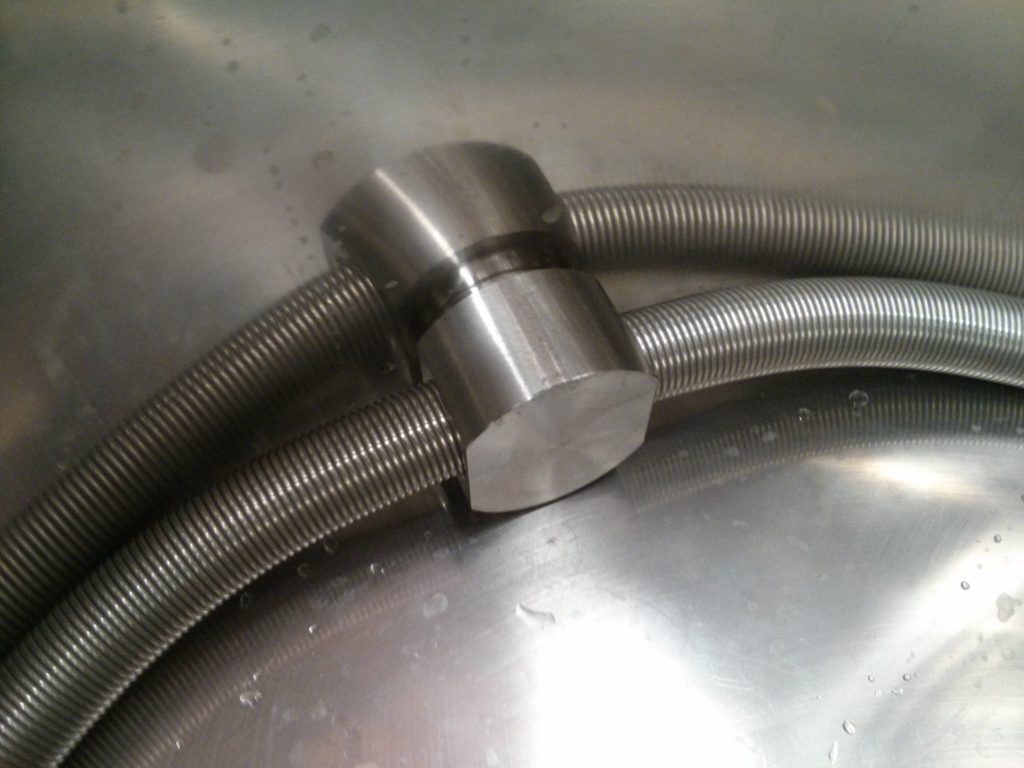
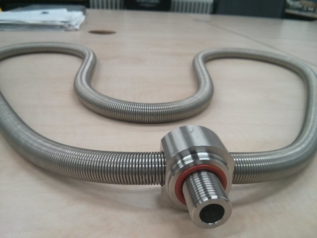
Instead of a filter bottom, I am going to use a LauterHelix. It is a German invention by Matthias Hoßfeld. See:

The idea is to use a stainless steel spring to filter your mash. If you bend the spring, you create tiny slots in the bends. If the spring is bent with a diamter of 20cm, the slits are 0.5mm.
This way you create a flexible and very easy to clean manifold. And the end of brew day, you just unscrew it from the T-piece and clean in in the sink.
We used it once now and are quite happy with it. If you have a very thick mash, you just have to take care that you do not stir in a way that exposes the spring to air, which will let air go to the pump. Once we knew that, it was easy going.
Matthias only tested it with gravity fed sparging so far, but pumping through it seemed to work okay.
I cannot say much about efficiency yet, because there were other factors that were sub-optimal. When the rest of my setup is ready, and my temp profiles are completely reproducible, it will be a nice experiment to lay a false bottom on top of the spring to see if it makes a difference.
We are also going to use such a spring as a hop filter in the kettle.
We didn't like the simple plumbing tee that originally shipped with the LauterHelix, so we designed and CNC'd our own, with an integrated O-ring.
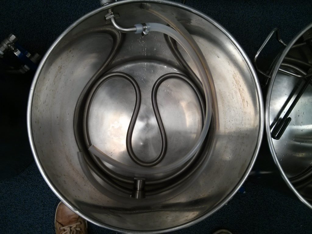
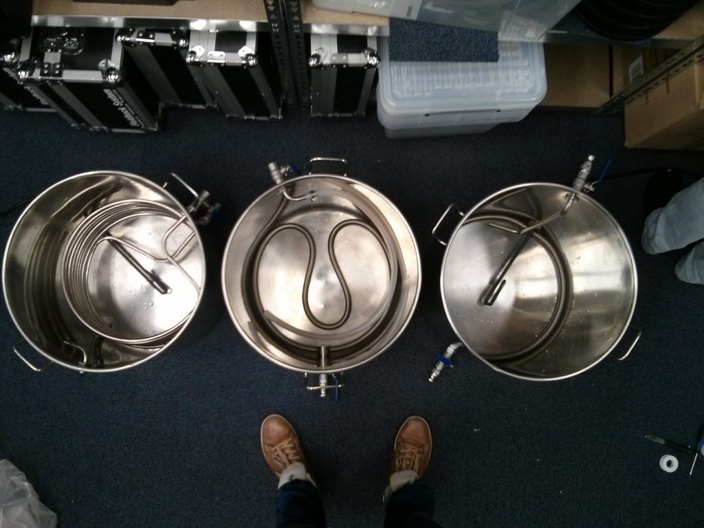
Here are the 3 kettles when we had just assembled them. The spring in the kettle (right) is too tight. Flow stopped during CFC cooling, but was resolved by bending the spring bit more. I will just shorten the spring to resolve this.
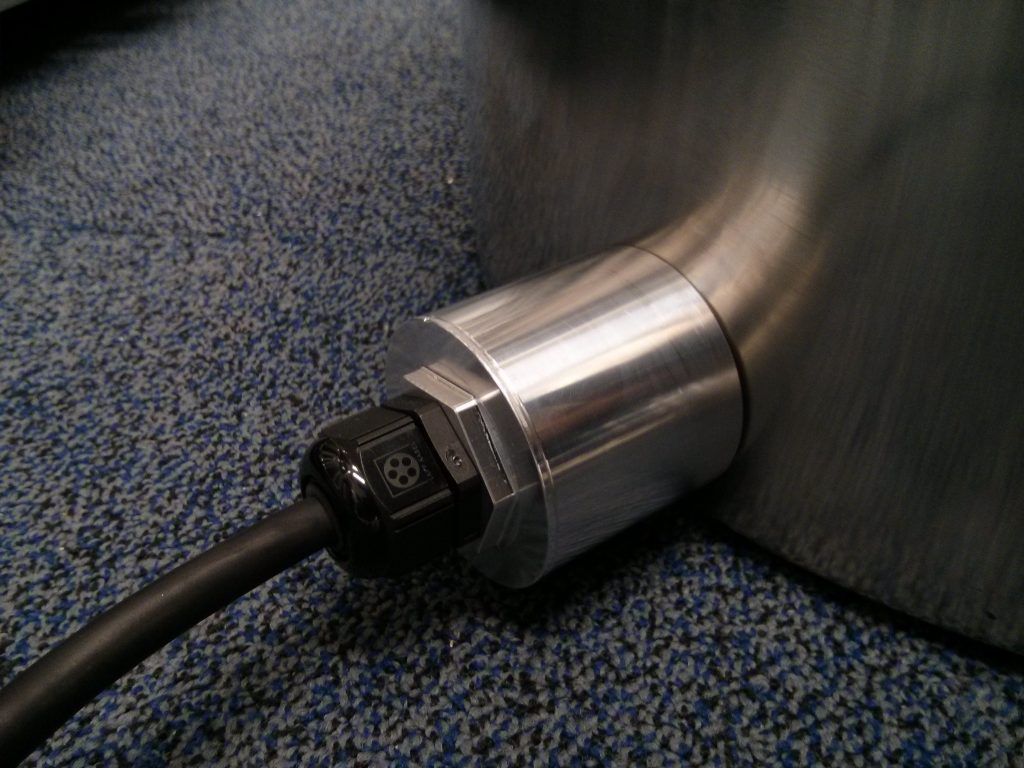
Another custom is our heating element enclosure, made from aluminum.
More pics on twitter:

And finally we have our custom fitting that is mounted on our inlets, outlets and HERMS coils:
It has an integrated O-ring groove and seals on the inside of the kettle. The O-ring groove is completely hidden behind stainless steel when a locknut on the outside is tightened.
This is our second version and it works well. We did some last design changes (round face with a hex behind it) and I will start production of the third version soon.
More updates soon The brewery is a mess of tools and parts now.
I plan to show off the brewery in its entirety 1-2 weeks, but here is a sneak preview to keep the discussion going.
Instead of a filter bottom, I am going to use a LauterHelix. It is a German invention by Matthias Hoßfeld. See:
The idea is to use a stainless steel spring to filter your mash. If you bend the spring, you create tiny slots in the bends. If the spring is bent with a diamter of 20cm, the slits are 0.5mm.
This way you create a flexible and very easy to clean manifold. And the end of brew day, you just unscrew it from the T-piece and clean in in the sink.
We used it once now and are quite happy with it. If you have a very thick mash, you just have to take care that you do not stir in a way that exposes the spring to air, which will let air go to the pump. Once we knew that, it was easy going.
Matthias only tested it with gravity fed sparging so far, but pumping through it seemed to work okay.
I cannot say much about efficiency yet, because there were other factors that were sub-optimal. When the rest of my setup is ready, and my temp profiles are completely reproducible, it will be a nice experiment to lay a false bottom on top of the spring to see if it makes a difference.
We are also going to use such a spring as a hop filter in the kettle.
We didn't like the simple plumbing tee that originally shipped with the LauterHelix, so we designed and CNC'd our own, with an integrated O-ring.
Here are the 3 kettles when we had just assembled them. The spring in the kettle (right) is too tight. Flow stopped during CFC cooling, but was resolved by bending the spring bit more. I will just shorten the spring to resolve this.
Another custom is our heating element enclosure, made from aluminum.
More pics on twitter:
And finally we have our custom fitting that is mounted on our inlets, outlets and HERMS coils:
It has an integrated O-ring groove and seals on the inside of the kettle. The O-ring groove is completely hidden behind stainless steel when a locknut on the outside is tightened.
This is our second version and it works well. We did some last design changes (round face with a hex behind it) and I will start production of the third version soon.
More updates soon
The brewery is a mess of tools and parts now.wbarber69
Well-Known Member
- Joined
- Oct 13, 2013
- Messages
- 2,191
- Reaction score
- 263
Perty! I never thought about using springs! That's a great idea to get the most out of your mash tun. To solve false bottom from caving in I just use the support ring that came with my brewhardware.com false bottom.
Similar threads
- Replies
- 25
- Views
- 955
