Auber brew panel problem

Homebrew Talk - Beer, Wine, Mead, & Cider Brewing Discussion Forum

Help Support Homebrew Talk - Beer, Wine, Mead, & Cider Brewing Discussion Forum:

This site may earn a commission from merchant affiliate links, including eBay, Amazon, and others.

aquaman02

Well-Known Member
Joined
Jul 20, 2017
Messages
52
Reaction score
7
Finally got everything up and running and decided to to a test boil seeing how long to bring to a boil and find my boil off rate for 60min. I went to do a whirlpool at the end to test out the pumps. As soon as I turned the pump 1 switch on, the main GFCI breaker tripped in my sub-panel. Not sure why this is. Pumps work fine if plugged into an independent outlet.

4 wire from panel to outlet to brew panel. Neutral hooked up to outlets. Outlets are grounded to main input. Why could this be happening. Everything with the element seemed to work fine.
 
Last edited:
My understanding is that GFCI detects a mismatch in current on the hot and neutral lines. If it's tripping, there's got to be a secondary path for some current.

Does it do this if you plug in something different like a lamp or something?
 
If the panel works but switching on a 120v load trips the gfci either the load has a earth fault( leakage to earth) or its not returning current to neutral but instead earth.

Something miss wired mixing neutral and earth to the panel might work for 240V loads but significant 120V loads cauld cause enough to trip the gfci.

Earth and neutral must be kept separate downstream of the gfci.
 
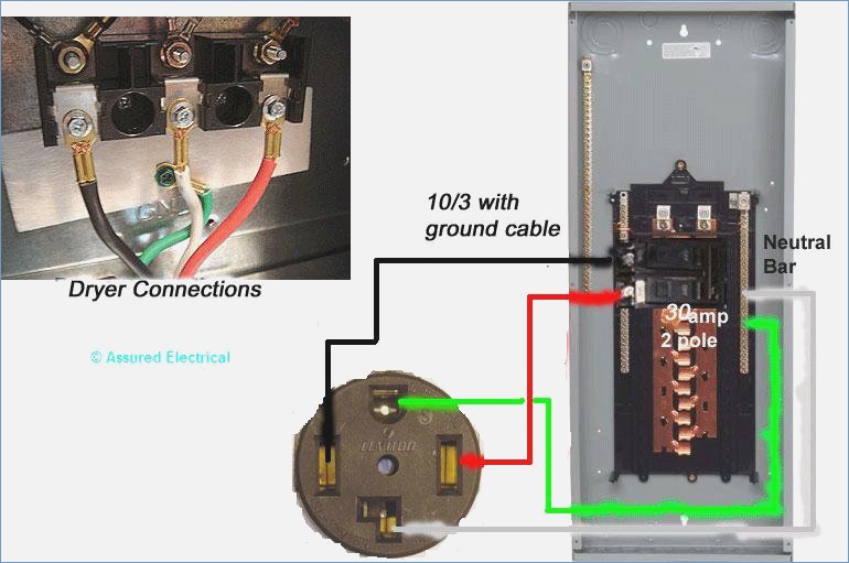
When wiring my EBC-SV controller to a 30A 220V GFCI I followed a similar diagram as below. Although sub-panels are not allowed by code in my area.

dryer-outlet-wiring-diagram-4-prong-of-4-prong-outlet-wiring-diagram.jpg
 
If the panel works but switching on a 120v load trips the gfci either the load has a earth fault( leakage to earth) or its not returning current to neutral but instead earth.

Something miss wired mixing neutral and earth to the panel might work for 240V loads but significant 120V loads cauld cause enough to trip the gfci.

Earth and neutral must be kept separate downstream of the gfci.
It does this with anything that is plugged into the pump outlets on the back. I even tried a desktop LED light. The main sub-panel has 4 wires with white going to a neutral bus bar and green going to the negative bar. White is plugged into the silver tab on the stove outlet. Power cable has white also going to silver tab on both ends. In the control panel White is routed directly to the two outlets. They also have green wire going from green power input directly to outlets. The hot is run from each switch to the last tab on the outlets. Not sure why this is happening.
 
The main sub-panel has 4 wires with white going to a neutral bus bar and green going to the negative bar. White is plugged into the silver tab on the stove outlet. Power cable has white also going to silver tab on both ends. In the control panel White is routed directly to the two outlets. They also have green wire going from green power input directly to outlets. The hot is run from each switch to the last tab on the outlets. Not sure why this is happening.
I think having a few pictures would make debugging your issue easier.
 
Is your neutral landed on the GFCI breaker instead of your neutral bus bar?
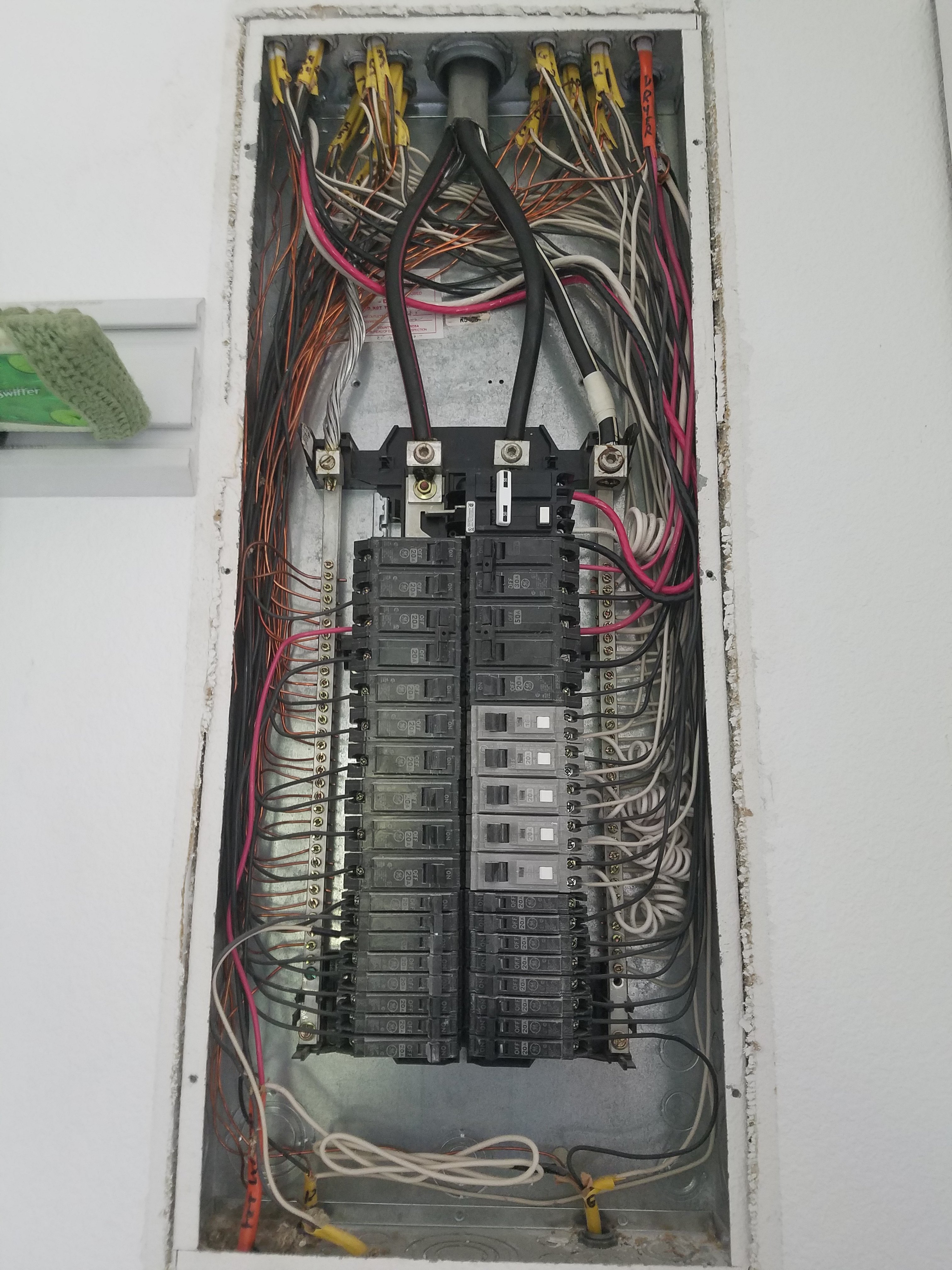
This is a picture of my main subpanel with the 50a Gfci breaker on the top right. Hots going to the breaker. White going to neutral bar. Ground going to ground bar on left. Not sure why it keeps tripping. I checked the outlet and it is wired correct, as well as the power cable and the input at the control panel.
20180626_164315.jpg
 
Last edited:
From what I can see in the picture it doesn’t look like the neutral from your outlet is hooked up to the GFCI breaker. The GFCI compares the total current on both hots and the neutral. If the currents aren’t equal (or technically total up to zero) it will trip. If you hook up the neutral to the ground bar it won’t see the neutral current which will definitely cause it to trip.

The attachment in post #8 isn’t loading for me.
 
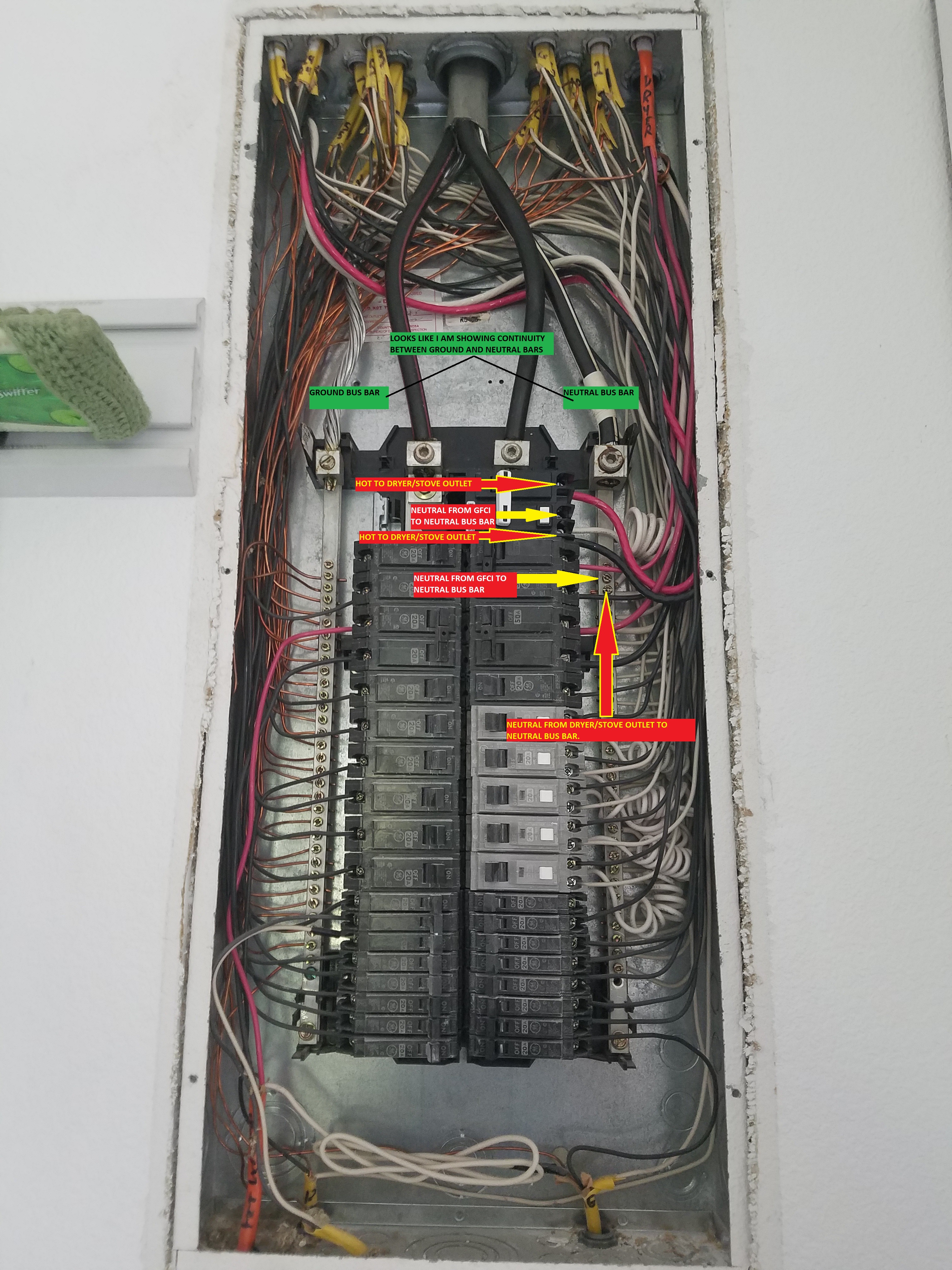
Yes. my white pigtail from the GFCI is hooked up to the neutral bar on the right. I tried to label everything for easier viewing. Only thing I did not label was the ground wire on the top of the ground bus bar on the left.
Subpanel with 50A GFCI.jpg
 
Actually, looking at the instructions. Is the pigtail supposed to hook to the neutral bar and the white neutral wire coming from the outlet supposed to hook directly to the gfci breaker instead of the bus bar like I have above?
 
WOW! Just installed the correct 30A breaker and actually hooked it up correctly with pigtail neutral going to the neutral bus bar and the white neutral from the outlet directly to the gfci.. and WAHLA!! My 120v outlets work now. Woohoo.

Thanks for all the help guys. Now I have to rewire the jumpers to my illuminated switches that I had removed for troubleshooting.
 
If it makes you feel any better I’m an electrical engineer and made the exact same mistake when putting in my 60A GFCI.
 
Back
Top