Another DYI glycol chiller

Homebrew Talk - Beer, Wine, Mead, & Cider Brewing Discussion Forum

Help Support Homebrew Talk - Beer, Wine, Mead, & Cider Brewing Discussion Forum:

This site may earn a commission from merchant affiliate links, including eBay, Amazon, and others.

Dland

Supporting Member
HBT Supporter
Joined
May 28, 2018
Messages
3,033
Reaction score
2,432
IMG_1590.JPG
IMG_1592.JPG
IMG_1602.JPG
IMG_1607.JPG
IMG_1608.JPG
Thought I'd share my take on the window AC chiller. AC gutted of all controls. Inkbird 308 temp probe in soldered off copper tube. 1300 GPM glycol pump run off separate controller, this is larger one moorbeer sells.

Chiller wrapped with 2 inch 'discharge hose'. Truck mat floor insulation on fermentor cone. Am going to further secure hose and insulate more. Hose held up by steel rods hose clamped to fermentor stand.
 
Last edited:
Hey @Dland , can you provide more detail as to what you did to bypass the controls. I've been saving an old A/C that has a bad motherboard for this purpose. Would be interested to see how you did it.
 
Sure, all I did was only use the 120V part of the circuit. The control boards are gone, no more low current transformer. Just the compressor, fan and capacitor.

Leave connections to capacitor same, but lead to board or transformer no longer needed.

The unit I used had a two speed fan, I figured out which wire was high speed and jumped it into circuit.

If you are gutting out a AC unit the way I did, try to locate the circuit diagram decal on some part you will likely chuck, and save for future reference. (even though you would need a microscope to read it, might be handy some day).
 
First live test today, brought 11 gallons of wort down from 71F to 54 in a 72F cellar in 2.75 hours. I'm quite pleased, something worked out better than expected.

I did wrap some more temporary insulation on it and pipe insulation on feed tubes since last picture.
 
Kegged the first glycol cooled batch of lager today and managed to wrap the blue hose around the two kegs and insulate for temp controlled spunding.

The flat discharge hose works great transferring cold to fermentor and kegs. One problem I am having is the hose changes position after repeated pressure/no pressure cycles and tends to constrict on itself.

I am going to have to figure a better way to secure the hose in position so it does not have to be adjusted to improve flow during use. I had to mess with it 3 or 4 times in 10 days to keep flow going.

If anyone else has ever worked with this, I'd like to hear what your solution was. I got the idea for using this hose from someone on this forum(I forget who), so I know others have used this.
 
View attachment 637516 View attachment 637517 View attachment 637518 View attachment 637519 View attachment 637520 Thought I'd share my take on the window AC chiller. AC gutted of all controls. Inkbird 308 temp probe in soldered off copper tube. 1300 GPM glycol pump run off separate controller, this is larger one moorbeer sells.

Chiller wrapped with 2 inch 'discharge hose'. Truck mat floor insulation on fermentor cone. Am going to further secure hose and insulate more. Hose held up by steel rods hose clamped to fermentor stand.
thats the same blue discharge hose I use on on three of my stainless conicals including a chinese clone of that older spike model..I used silicone heat wrap on the cones to heat for diecetal.
Im using a 1/3hp chiller myself with brucontrol but theres plenty of cooling power to chill more as ive done 4 conicals off my system at home with no issues...
Just a heads up to anyone with plastic conicals... this hose method does not work effectively on plastic.. I tried it.
 
Update on the hose positioning.

One, I figured out flow in hose had stopped not due to kinking or moving as I thought, but intermittent failure(which became constant) of cheap glycol pump. The impeller was slipping on the shaft. Solved by buying a real pump, commercial grade, as opposed to what is being sold in some brew places, which is actually a cheap pond fountain pump.

Two, I rig the flat hose to stay in position with some 12G insulated single strand copper wire I had around. May not look elegant, (so it matches rest of my rig, haha) but it works.
 
aghhh having a time making my own .... Not an electrician.... just a chemist. how do I orient these wires coming out of my 5000 btu frigidaire to connect to the inkbird? I get a little confused when it comes to the capacitor. I know to solder the two red wires of the thermostat together, but what other wires need to be soldered and put into the inkbird? how can I add the switch that will run my wavemaker?
 

Attachments

  • wires.jpeg
    wires.jpeg
    4.4 MB · Views: 54
Hopefully you saved the wiring diagram, might save you some time. What I did was eliminate the control boards, the whole low voltage circuit, and left the 120V circuit intact including original hook up to capacitor and power cord. The only thing I recall jumping into the 120V circuit was the one of the hot wires to the fan. Just pick one of those, if they run the fan at different speeds, pick the high speed one. On my unit they were the same,( speed reduction was controlled by now removed board).

In picture below, at the very bottom, is the power cord with plug that goes to temp controller. The red wire shown at front of unit is unconnected and was taped off or unplugged from capacitor, this went to the control board. Hope this helps.
 

Attachments

  • IMG_1598.JPG
    IMG_1598.JPG
    103.1 KB · Views: 57
20200430_071513.jpg
20200428_211846-jpg.678006
20200430_071526.jpg
20200430_071543.jpg

Ok so here is what I'm working with and first and foremost I am extremely grateful for any and all input. But for the two knobs placed next to each other the thermostat is on the right which I assume I will wire together and run straight to the control? The left is the controller. Other than that how do I wire this into the ink bird and what wires do I need to pull and from where based off the diagram given? Also how do I wire in a switch that will run my wave runner? A guy from home brew talk did this exact setup but doesn't have the pics up anymore and gives a vague description on the homebrew talk page. I will send you a free true essential oil for your help...any type you want if you're into that type of thing. Once again thank you in advance!
 

Attachments

  • 20200428_211846.jpg
    20200428_211846.jpg
    2.1 MB · Views: 865
But for the two knobs placed next to each other the thermostat is on the right which I assume I will wire together and run straight to the control? The left is the controller. Other than that how do I wire this into the ink bird and what wires do I need to pull and from where based off the diagram given? Also how do I wire in a switch that will run my wave runner?

Probably you can do away with knobs and temp sensor. The Inkbird 308 controls temp, short cycle protection, and has temp sensor , which goes into your glycol bath. I recommend using a thermowell rather than direct dunking it, (I used soldered off copper tube, mentioned in my earlier posts).

I saw some examples with wave generators in utube, but don't see the point if you are going to circulate glycol with a submersable pump (which is run by another Inkbird 308 and temp attached to fermentor) pump moves glycol solution around fine, extra motion not needed..
 
fair enough but I still want to attach the wave generator since i already have it and this thing truly ices over quickly. but how do I hook the inkbird up to the unit? which wires do I use as the hot wires and neutral and what wires do I need to link to them and which wires need to bypass?? Im good with colors... not good with electrical vernacular. Hopefully this will teach me a little bit. And where would I add the switch if I want to? tired of needing ice for my distillation condensers and havent even built the platform for this thing yet haha. anyways hopefully you can turn some lights on in my head.
also .... I must let it be known I am working with an STC-1000 not the 308. Hope that helps a little ... i can post pics of the system and wiring schematic if that helps.

and for those asking ... the glass piece is required for taking tension off the main operating system ;)
 
Ahh the STC-1000, ...I'll admit the wiring instructions on back of those are almost useless. You have to provide your own plugs and wire, I cut up a extension cord or two when I wired mine, used for first Fermwrap a while back. I might be able to dig up mine and take picture later, but it would likely still not be as clear as this, I think this is the one I used:


If you have access and $35, I'd still recommend a 308. Wire connections self evident, more sturdy, water resistant, and more accureate ( My STC-1000 reads 3-4 degrees off).
 
Already in deep with the 1000.... this video requires plugging in two separate plugs where the homebrew talk page wires the stc1000 off of one power supply. I want to wire all three hotties in. One for power supply of the stc and the fan and the compressor to the cold switch.. but what wires in my a.c. do I route to use ? Do I take the wires straight from the compressor to bypass capacitor, from the controller, or straight from the devices? And which wires are they.... ???
 
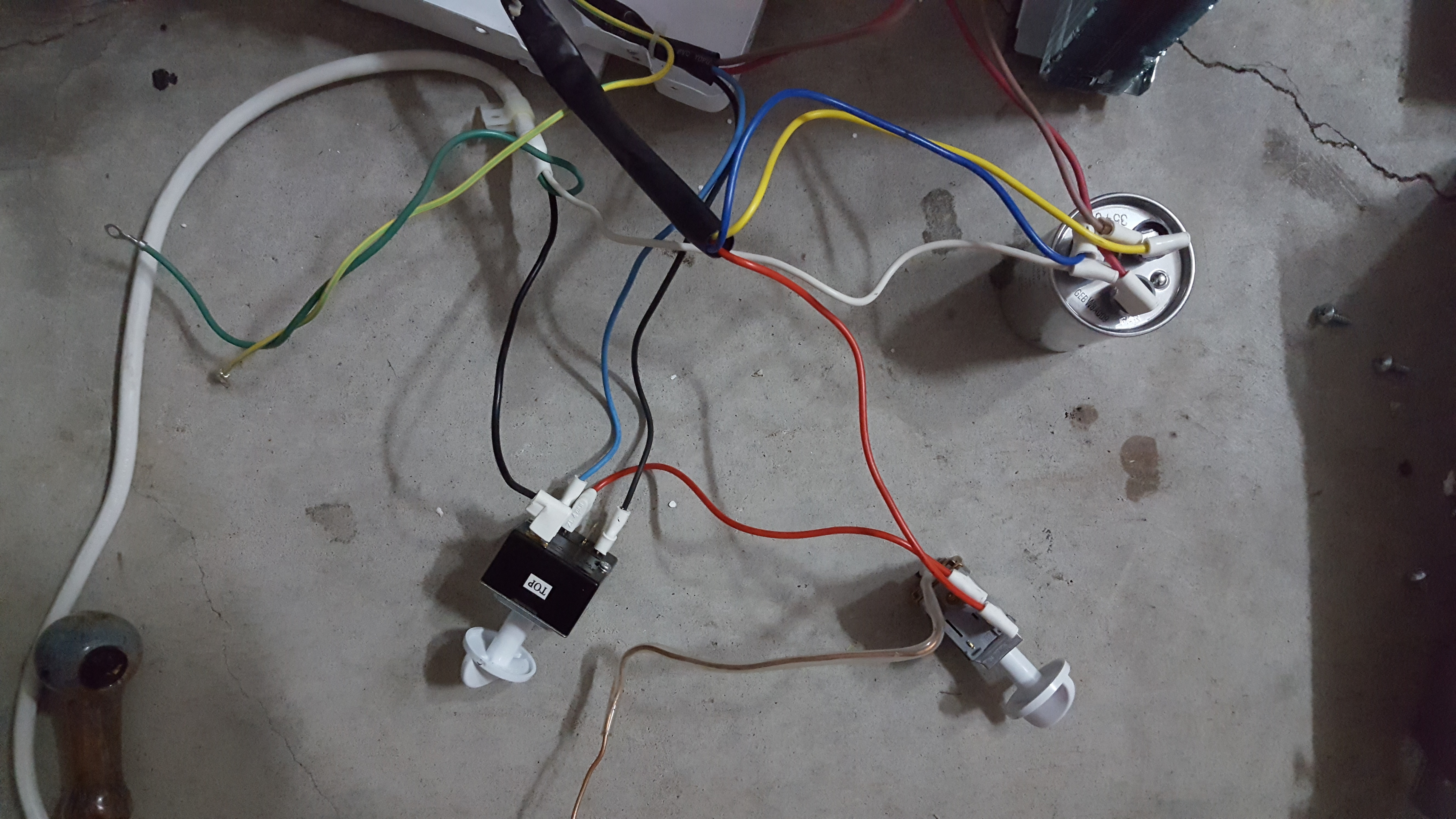
It looks like it is already hooked up. Leave capacitor wires as they are. The green grounds to chassis, and it looks like yellow/green to fan is ground too.

You could leave switches in position so always on. I'd try this first, if it works I'd leave it at that.

If you have to remove switches from circuit, below is an only semi educated guess from pictures. Wire colors are not completely standardized for internal appliance wiring, just so you know, and I am not an electrician or HVAC tech by trade, so be advised.

Again, do not unplug capacitor, you need it. Since two of the three wires from compressor are hooked to capacitor, looks like the red one to compressor may go to black power cord. If you look at your printed diagram, power cord to compressor is red or red/black to overload protector, the actual black part of cord may be under wire sheath, cant tell from here. In any case, you should leave overload protector in circuit.

You will also need to hook either blue and/or black from fan to the black on power cord.

Good luck, & for best maybe hold off on pipe while you are trying this. {;
 
So looking over schematic I have an idea and I wanted to run it by you .... looking at the power cord... all we need is power to the inkbird stc1000 and power to AC for now and I can figure out wave maker later. so is it possible for me to run the hot black wire to inkbird power interface and wingnut it in and take the white neutral wire and run it out of the inkbird power interface and wingnut it in where the white wire runs back into the power cord? And for the cooling interface i run the black wire into the cooling interface and then run the black wire out of the interface as the neutral wire leading into the rest of the unit? after all it is just a switch right? and then wingnut/solder the two red wires for the thermostat to each other???

also... hold off on the pipe? I thought you were trying to help this project along!? don't try to sabotage me after we have come this far! ;))
 
Probably, uh, maybe..but not sure if able convert your verbage into wiring schematic. If you wire it as shown in the utube video I linked above, you'll likely save yourself some headaches.

Remember..., there are two distinct loads, one is power to the controller, the other is power to your chiller. The stc 1000 does not supply the power to chiller, it only switches it. Yes you can hook it up with only one power cord, but it might be easier to mess it up.

Here is a more complicated one if you want..,,{: This guy pretty much turned his 1000 into a bulky, non spill proof version of a 308.


Or skip to around 3:43 on this one to see an elegant version of what I think you want to do:


There, you are set up for a whole night's entertainment. Good luck!
 
Ok .... going to be a crappy drawing, but Electricity is not my field and using finger mouse with gimp is proving rather difficult. difference in color of wires is to aid in what would be visual confusion of using similar colors for neutral and hot wiring. so the purplish/blue is hotwire, black is the continuation of the hot wire as a neutral and 2 is neutral back into the the wall for itc power supply .... is this ....going to kill me? or hopefully work?
2020-04-30 21.15.41.jpg
 
@Dland can you provide an update on how this blue discharge hose has worked for you? I’ve moved to fermenting in a 15 gallon torpedo keg (10 gallon batches) and am interested in purchasing a glycol chiller if this method will work.

How low can you get on a cold crash?
 
@Dland can you provide an update on how this blue discharge hose has worked for you? I’ve moved to fermenting in a 15 gallon torpedo keg (10 gallon batches) and am interested in purchasing a glycol chiller if this method will work.

How low can you get on a cold crash?

The discharge hose is working fine. I don't cold crash with it, as I rack to kegs and spund, then crash these in freezer. But I'm pretty sure it would work fine if vessel is insulated and ambient temp not too high. It will drop 10 gallons by 20F in about an hour without working that hard.
 
Back
Top