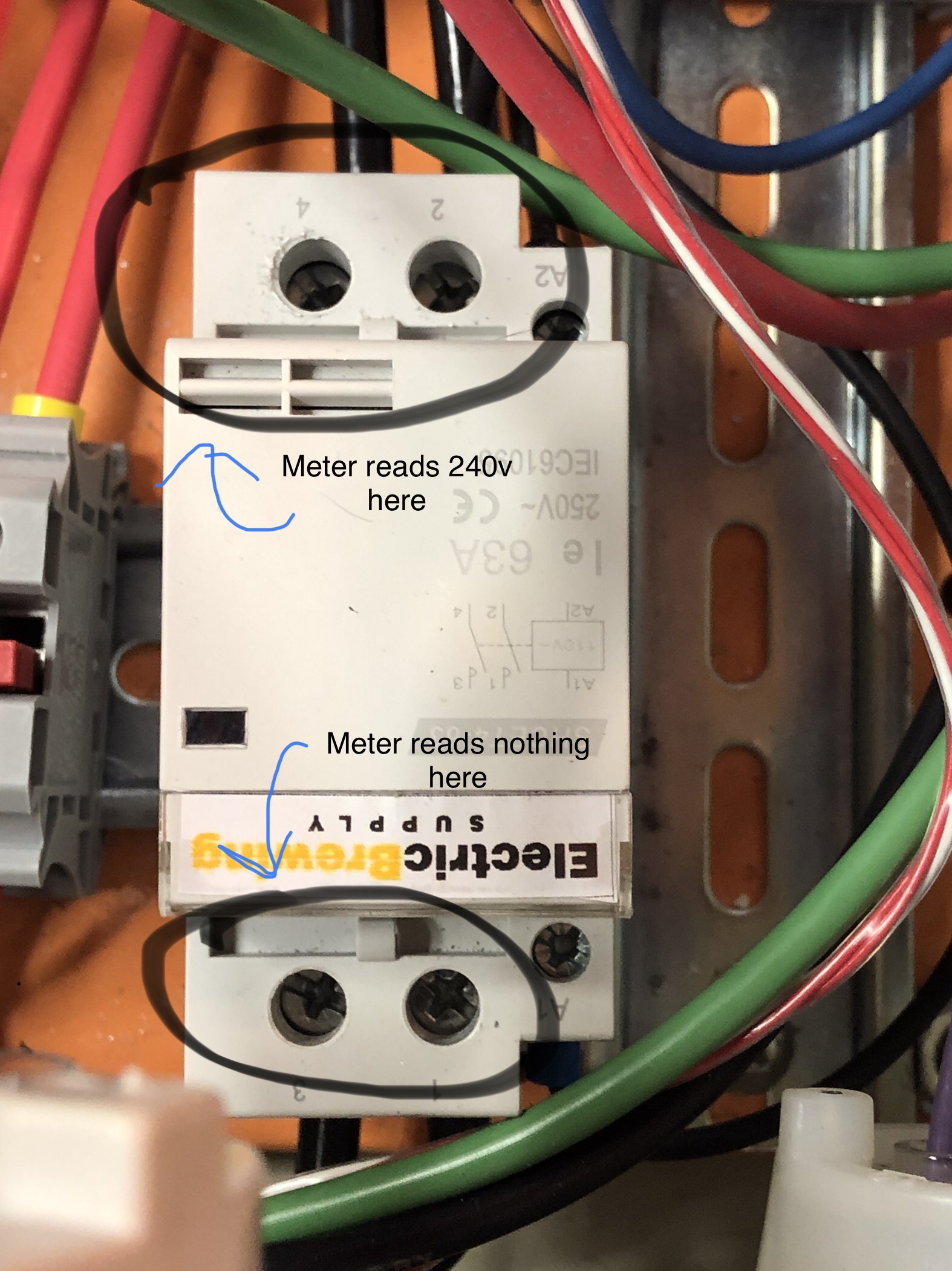
I have final wired up my control panel, not the prettiest wiring job out there but got it completed. The issue I’m having is that I am getting 240 volts coming into the the contactor but am not getting anything on the output side. With that being said, the unit does not power on at all. I was told that I may have fried the coil inside, so I ordered a replacement one and still have the same issue. I have posted a picture to help visualize what I Am talking about. Any suggestions/ thoughts would be appreciated.
You are using an out of date browser. It may not display this or other websites correctly.
You should upgrade or use an alternative browser.
You should upgrade or use an alternative browser.
50 amp control panel need help troubleshooting
- Thread starter jblockbrew
- Start date

Help Support Homebrew Talk:
This site may earn a commission from merchant affiliate
links, including eBay, Amazon, and others.
Sounds like your contactor coil is wired wrong, or the switch controlling power to the coil is wired wrong or faulty. Can't trace any wires in that photo, so no way to figure out what might be wrong.
Why do you have all black wires connected to the contactor input and output terminals? Normally, a two pole contactor is used to switch hot-1 and hot-2. These two power phases should never use the same color wire - it's just asking for trouble, and makes trouble shooting much more difficult. Usual colors are black for one hot and red for the other hot (and which color goes with which phase needs to be consistent throughout the panel.)
Brew on
Shouldn't actually matter, as the internal connection is just made by simple contacts.Looks like you have incoming power on output side.... At least thay is what It looks like to me. p1 and p2 are input
Brew on
Without a diagram or very detailed pictures, there's nothing definitive to say. However, Doug's suggestion to use different color wires is crucial for even your own troubleshooting.
I use black for L1 hot, red for L2 hot, white for neutral and green for ground. I like using blue or yellow for the signal voltage to the SSR.
What is the coil voltage rating on the contactor? If you put a meter across the contactor coil terminals, does it have that rated voltage applied? Until then, the contactor will not close.
Looks like you have incoming power on output side.... At least thay is what It looks like to me. p1 and p2 are input
There really is no directionality on a contactor but P1 and P2 certainly are not inputs. P1 is connected to P2 when the coil energizes. If you wired L1 to P1 and L2 to P2, closing the contactor results in a 240 volt short.


$7.79 ($7.79 / Count)
Craft A Brew - LalBrew Voss™ - Kveik Ale Yeast - For Craft Lagers - Ingredients for Home Brewing - Beer Making Supplies - (1 Pack)
Craft a Brew


$33.99 ($17.00 / Count)
$41.99 ($21.00 / Count)
2 Pack 1 Gallon Large Fermentation Jars with 3 Airlocks and 2 SCREW Lids(100% Airtight Heavy Duty Lid w Silicone) - Wide Mouth Glass Jars w Scale Mark - Pickle Jars for Sauerkraut, Sourdough Starter
Qianfenie Direct

$176.97
1pc Commercial Keg Manifold 2" Tri Clamp,Ball Lock Tapping Head,Pressure Gauge/Adjustable PRV for Kegging,Fermentation Control
hanhanbaihuoxiaoshoudian


$20.94
$29.99
The Brew Your Own Big Book of Clone Recipes: Featuring 300 Homebrew Recipes from Your Favorite Breweries
Amazon.com


$22.00 ($623.23 / Ounce)
AMZLMPKNTW Ball Lock Sample Faucet 30cm Reinforced Silicone Hose Secondary Fermentation Homebrew Kegging joyful
无为中南商贸有限公司


$44.99
$49.95
Craft A Brew - Mead Making Kit – Reusable Make Your Own Mead Kit – Yields 1 Gallon of Mead
Craft a Brew
![Craft A Brew - Safale S-04 Dry Yeast - Fermentis - English Ale Dry Yeast - For English and American Ales and Hard Apple Ciders - Ingredients for Home Brewing - Beer Making Supplies - [1 Pack]](https://m.media-amazon.com/images/I/41fVGNh6JfL._SL500_.jpg)
$6.95 ($17.38 / Ounce)
$7.47 ($18.68 / Ounce)
Craft A Brew - Safale S-04 Dry Yeast - Fermentis - English Ale Dry Yeast - For English and American Ales and Hard Apple Ciders - Ingredients for Home Brewing - Beer Making Supplies - [1 Pack]
Hobby Homebrew


$53.24
1pc Hose Barb/MFL 1.5" Tri Clamp to Ball Lock Post Liquid Gas Homebrew Kegging Fermentation Parts Brewer Hardware SUS304(Gas MFL)
Guangshui Weilu You Trading Co., Ltd


$76.92 ($2,179.04 / Ounce)
Brewing accessories 1.5" Tri Clamp to Ball Lock Post Liquid Gas Homebrew Kegging Fermentation Parts Brewer Hardware SUS304 Brewing accessories(Gas Hose Barb)
chuhanhandianzishangwu


$53.24
1pc Hose Barb/MFL 1.5" Tri Clamp to Ball Lock Post Liquid Gas Homebrew Kegging Fermentation Parts Brewer Hardware SUS304(Liquid Hose Barb)
yunchengshiyanhuqucuichendianzishangwuyouxiangongsi


$479.00
$559.00
EdgeStar KC1000SS Craft Brew Kegerator for 1/6 Barrel and Cornelius Kegs
Amazon.com


$49.95 ($0.08 / Fl Oz)
$52.99 ($0.08 / Fl Oz)
Brewer's Best - 1073 - Home Brew Beer Ingredient Kit (5 gallon), (Blueberry Honey Ale) Golden
Amazon.com


$58.16
HUIZHUGS Brewing Equipment Keg Ball Lock Faucet 30cm Reinforced Silicone Hose Secondary Fermentation Homebrew Kegging Brewing Equipment
xiangshuizhenzhanglingfengshop

$719.00
$799.00
EdgeStar KC2000TWIN Full Size Dual Tap Kegerator & Draft Beer Dispenser - Black
Amazon.com


ITV
Well-Known Member
Zooming in on the photo, the contactor coil voltage is 110VAC.
For the contactor to pull-in you will need 120VAC across A1 & A2.
Without a schematic this is as far as we can help you.
For the contactor to pull-in you will need 120VAC across A1 & A2.
Without a schematic this is as far as we can help you.
fbold1
Brew Nut
Coil wired right, correct coil voltage?I have final wired up my control panel, not the prettiest wiring job out there but got it completed. The issue I’m having is that I am getting 240 volts coming into the the contactor but am not getting anything on the output side. With that being said, the unit does not power on at all. I was told that I may have fried the coil inside, so I ordered a replacement one and still have the same issue. I have posted a picture to help visualize what I Am talking about. Any suggestions/ thoughts would be appreciated.
ITV
Well-Known Member
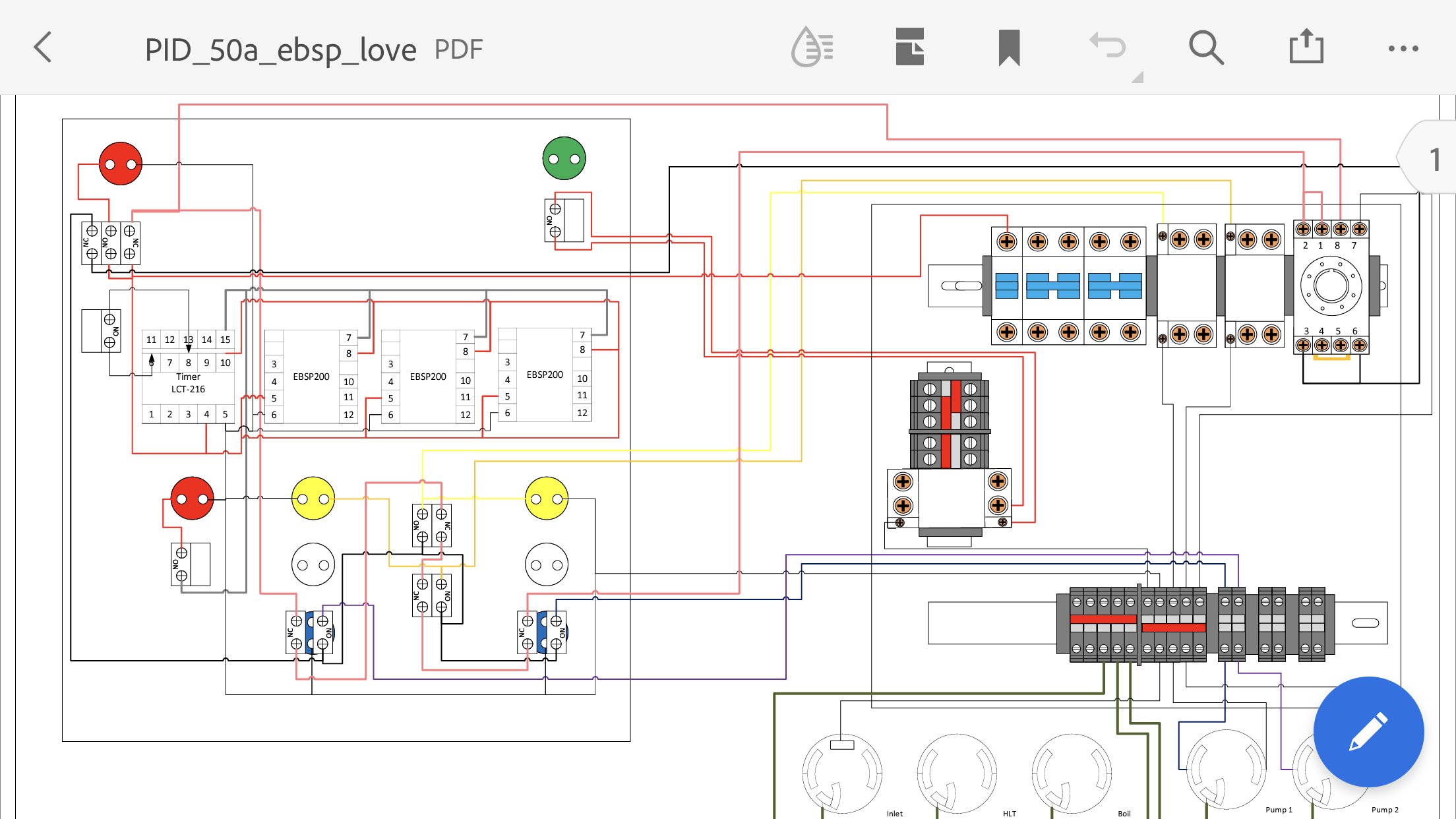
It appears that you only included one page of the schematics, I have attached what I believe the schematic set for your unit.
Your photo appears to be the main contactor. The coil is wired through the Power Off/On selector switch. With the switch in the on position will send 120V to the coil, the other side of the coil should be the neutral wire. You should be able to measure 120VAC across A1 & A2, if not then something is wired incorrectly.
It is also important that the wire insulation be properly stripped (no broken strands and stripped to the proper length). The wire lugs and wire terminals should also be tightened to the proper torque (done by feel to an experienced electrician/panel wireman to prevent loose connections.
Attachments
check the control wiring from the 1, 2, 3 or 4 terminals (240v terminals) up to the on-off key switch. that is the 120v source for operating the coil. you should have 120v at one end of the key switch contact all the time. if you accidentally hooked up to the load side of the contactor, you won't have 120v to operate the coil. flip control wire to opposite side of contactor.
Thank you for the attachment. You are correct I only attached one page, I tried to get all the wiring that was done,however the ones you attached have more information than what I have. I have never seen this schematic on their website. When I get the other color wires I guess I will start all over and retrace my wiring using the attachment you included. Thanks for all the help.It appears that you only included one page of the schematics, I have attached what I believe the schematic set for your unit.
Your photo appears to be the main contactor. The coil is wired through the Power Off/On selector switch. With the switch in the on position will send 120V to the coil, the other side of the coil should be the neutral wire. You should be able to measure 120VAC across A1 & A2, if not then something is wired incorrectly.
It is also important that the wire insulation be properly stripped (no broken strands and stripped to the proper length). The wire lugs and wire terminals should also be tightened to the proper torque (done by feel to an experienced electrician/panel wireman to prevent loose connections.
ITV
Well-Known Member
I agree with itsnotrequired's assesment that the 120V source was incorrectly hooked up to the load side. If that is the case I suggest verifying all the wiring (with the power off).Thank you for the attachment. You are correct I only attached one page, I tried to get all the wiring that was done,however the ones you attached have more information than what I have. I have never seen this schematic on their website. When I get the other color wires I guess I will start all over and retrace my wiring using the attachment you included. Thanks for all the help.
So I replaced all the black wire from the input with red and white and still not powering on. I believe that I have the contactor wired correctly according to the diagram. The wiring is not the neatest but will fix it when I fig out why it won’t power on. I also included how I have the inlet wired up.


 Thanks for your help.
Thanks for your help.ITV
Well-Known Member
It looks like the A2 on the main contactor is not wired to the other side of the Power On/Off switch, instead it looks like it is wired to another contactor coil.
Recheck your wiring for the Power On/Off switch circuit as well as the remaining wiring.
Recheck your wiring for the Power On/Off switch circuit as well as the remaining wiring.
Agree with above. The A2 on the 63A relay coil is connected to another A2 on another contactor. That's not going to provide the 120v to the coil.
It looks like the A2 on the main contactor is not wired to the other side of the Power On/Off switch, instead it looks like it is wired to another contactor coil.
Recheck your wiring for the Power On/Off switch circuit as well as the remaining wiring.
Agree with above. The A2 on the 63A relay coil is connected to another A2 on another contactor. That's not going to provide the 120v to the coil.
yup. looking at this expanded photo, there is a smaller conductor coming off terminal 2 of the main contactor. wiring gets a little clouded but looks like it is running off the photo, assume it is to the power on key switch (that is where it needs to go). the other conductor coming off that main key switch needs to go to the A2 terminal on the main contactor.
It looks like the A2 on the main contactor is not wired to the other side of the Power On/Off switch, instead it looks like it is wired to another contactor coil.
Recheck your wiring for the Power On/Off switch circuit as well as the remaining wiring.
This is what I see as well. The black wire coming off the A2 terminal of the main contactor needs to go to a switch that has the other terminal connected to the "black" hot bus/incoming hot.Agree with above. The A2 on the 63A relay coil is connected to another A2 on another contactor. That's not going to provide the 120v to the coil.
Brew on
Thank you for the attachment. You are correct I only attached one page, I tried to get all the wiring that was done,however the ones you attached have more information than what I have. I have never seen this schematic on their website. When I get the other color wires I guess I will start all over and retrace my wiring using the attachment you included. Thanks for all the help.
quick heads-up that page 1 and 5 of the pdf have a wiring error for the green power-on light on the door. it shows both wires for the light coming off the three terminal blocks that are jumpered together. these terminals are all at the same potential so the light will never turn on, even if powered. one wire needs to go to the set of two terminals below the isolation plat in that lineup of five terminals. this set of terminals is the other leg of the 240v circuit and will be at different potentials when energized, illuminating the light. looking at your recent photo, looks like the terminal blocks to the left of the main contactor are these five terminal blocks. the two smaller red wires on there go off the photo, assume they go to the light and looks like you have it wired correctly.
In case it's unclear what I think everyone is agreeing on... follow the yellow line that is right next to the black wire.

ITV
Well-Known Member
I can't stress enough to recheck all your wiring. If you don't feel up to the task, have someone qualified do it. A 50A 220V circuit is not something to experiment with.It looks like the A2 on the main contactor is not wired to the other side of the Power On/Off switch, instead it looks like it is wired to another contactor coil.
Recheck your wiring for the Power On/Off switch circuit as well as the remaining wiring.
quick heads-up that page 1 and 5 of the pdf have a wiring error for the green power-on light on the door. it shows both wires for the light coming off the three terminal blocks that are jumpered together. these terminals are all at the same potential so the light will never turn on, even if powered. one wire needs to go to the set of two terminals below the isolation plat in that lineup of five terminals. this set of terminals is the other leg of the 240v circuit and will be at different potentials when energized, illuminating the light. looking at your recent photo, looks like the terminal blocks to the left of the main contactor are these five terminal blocks. the two smaller red wires on there go off the photo, assume they go to the light and looks like you have it wired correctly.
I see that now comparing it to the original schematics I used, so I did not move those wires. Thanks for pointing it out.
I got that corrected and have added more colored wires and it powered, I know in the future to use more colored wires. I also found a couple of loose wires where they are not fitting into the terminals, and breakers properly due to the use of the ferrule’s. I thought that this would make connections easier but it did not. I won’t be using them again. So hopefully after I cut them all off and reattach everything it works. And yes ITV it is nothing to screw around with. I have always completely disconnected the power source and use extreme care when working with electricity. Thank you for all the help And suggestions.
ITV
Well-Known Member
I don't mean to be the A-hole, but I work in the power plant industry which personal protection is priorty. Please put your personel safety as a priorty and double check your wiring.
ITV
Well-Known Member
Another safety concern, I assume that you are feeding your control panel with a 50A, 2-pole, GFCI breaker.
Similar threads
- Replies
- 20
- Views
- 771
- Replies
- 37
- Views
- 3K
- Replies
- 0
- Views
- 155

Latest posts
-

-

-

-
How are You Measuring Fermentation Temperature?
- Latest: betarhoalphadelta
-

-
-

-
