• Please visit and share your knowledge at our sister communities:
  • If you have not, please join our official Homebrewing Facebook Group!

    Homebrewing Facebook Group

3bbl Electric Control Panel, power concerns.

Homebrew Talk

Help Support Homebrew Talk:

This site may earn a commission from merchant affiliate links, including eBay, Amazon, and others.
If I read it correctly, if you were to move the contactors in the 240v panels to between the circuit breakers and the SSRs, you would only have hot lines to the contactor line terminals when you have the panel off. As it stands, you would have hot lines both to the contactor line terminals and the SSR line terminals. Probably not a big deal, but something to consider.
 
Looks great to me. Good job. I believe that the 2 fuses shown in the controller diagram are no longer needed with your choice of the 5A breaker protection.

P-J

I revisited the diagram, I can do without the 5a and 1a fast blow. Without your above post I wouldn't have even looked back, so a BIG thank you for that.
I'm going to add a bypass switch and indicator light to the SSR / float switch circuit and then the design is complete and finished!

If I read it correctly, if you were to move the contactors in the 240v panels to between the circuit breakers and the SSRs, you would only have hot lines to the contactor line terminals when you have the panel off. As it stands, you would have hot lines both to the contactor line terminals and the SSR line terminals. Probably not a big deal, but something to consider.

The SSR's, contactors, relay for the pumps, basically everything goes open as soon as the E-stop is pushed. The E-Stop cuts the power to the PID's, they power the SSR's. Everything is dead with a push of that button.
 
If I read it correctly, if you were to move the contactors in the 240v panels to between the circuit breakers and the SSRs, you would only have hot lines to the contactor line terminals when you have the panel off. As it stands, you would have hot lines both to the contactor line terminals and the SSR line terminals. Probably not a big deal, but something to consider.

You might not be seeing it. There is an ON/OFF button for both the BOIL contactors and the HLT contactors located in the control panel. However, while making the (what I hope to be) final revisions, I added a key switch just after the E-Stop. It is redundant to say the least but I'm all about safety.
 
EDIT One last MAJOR revision is coming.

I want to take a moment to thank P-J, without whom I probably wouldn't have even been able to start this project. The drawings he provided are at the foundation of these revisions. I also want to thank 'da Kid and everyone else that have offered suggestions or pointed out potential problems.

WARNING- The diagrams below may look like P-J's diagrams but they are not, therefore they may contain mistakes. They were designed using a substantial amount of P-J's ground work. However at this point they are now vastly different. Caution should be taken if you intend to use them as a guide. YOU HAVE BEEN WARNED!
 
Looks good. Now get busy. :)

Looks like you can use 6ga copper if you are running THHN as the feeds.

http://cerrowire.com/files/file/ampacity2010.pdf

The ground:
You only need one ground per panel feed. Might as well use a 6ga for the Power Panels. (8ga would be acceptable)
Bond the panel covers with a ground wire as hinges are not considered a 'connection'
Bond the panel backplane to ground. The four mechanical bolts/nuts are not considered a 'connection'.
Throw one of these symbols on each of your prints at the ground terminal block
120px-Chassis_Ground.svg.png


Do you have a local source for wire?
If you can, get that MTW for the control wiring. 18ga will handle the 10A
We use Red for all 120v control. White for the neutrals of course.

Rad, I've enjoyed helping you reach your goal,
'da Kid
 
You'll love those liquid level probes.
Ours are used for water makeup.

Have you considered a Red Warning light wired into the N.C. side of that relay? (it's actually a control unit)
We use that contact as a 'low water' indicator and the makeup valve.

Just something else for you to wire up . . . . . . . :D

'da Kid
 
You might not be seeing it. There is an ON/OFF button for both the BOIL contactors and the HLT contactors located in the control panel. However, while making the (what I hope to be) final revisions, I added a key switch just after the E-Stop. It is redundant to say the least but I'm all about safety.

I probably wasn't clear, and it is a nitpicky suggestion anyway. My point was that when you use your control panel boil (or hlt) switch to turn off your boil (hlt) panel, there are potentially hot lines that terminate at the line in terminals of both the contactors and the SSRs. If you moved the contactors to come before the SSRs, then you would have potentially hot lines terminating at the line terminals of the contactors only (not the SSRs). Either way, you are cutting power to the elements using the contactors, but the latter method has fewer places where one could inadvertently touch a hot line. If you are never going to open the panel without disconnecting it from power, then it doesn't really matter.

The drawing looks great overall, but if it were mine I might make a couple of revisions (very subjective, though).

I would consider omitting the PID on/off switch, as I cannot think of scenarios where I would want the control panel powered on without the PIDs and timer working, or would care if they were.

I would also consider wiring 240v LEDs in parallel with each element, so I could see when each element was receiving power. If something is not working properly (e.g., an SSR fails closed), this can make it more obvious.

Great work!
 
<snip> I would consider omitting the PID on/off switch, as I cannot think of scenarios where I would want the control panel powered on without the PIDs and timer working, or would care if they were.
I was considering moving the BOIL/HLT switches to the PID output. I too would also like to read the water temp without heat being applied.

I would also consider wiring 240v LEDs in parallel with each element, so I could see when each element was receiving power. If something is not working properly (e.g., an SSR fails closed), this can make it more obvious.

Great work!

The more common Neon indicators would work great too. Maybe one in each heater housing.
161635-ProductImageURL.jpg


'da Kid
 
Last MAJOR revision is coming!

Thanks guys for making me critically think about some of your suggestions. I spent a hours contemplating functionality, safety, diagnostics and maintenance. After a long conversation with my father verbalizing operations it finally came altogether.
I though I was finished before but now I'm convinced.
I can't thank you all enough...
 
This Is The Final Revision. (I hope)

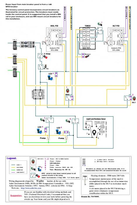
The controls panel now has a master key start and a master power indicator.
Both Power Panels have been completely redesigned from the ground up.
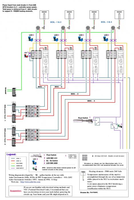
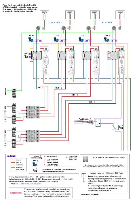
SSR's are now after the contactors. You can now push the (Boil or HLT) buttons and it will open both the contactors and the SSRs while not interfering with the display of PIDs and the timer on the Controls panel.
The timer now has momentary switch for STOP and RESET.
Each element has it's own 240V indicator to monitor that they are receiving power and quickly diagnose if there is a problem individually.
The float switch has a bypass switch.
Each pump has an indicator and one pump has an automated mode for liquid level resistance to use in vorlauf and lauter, and pump over to the boil kettle without pumping directly out of the MLT.

I can think of no other design inclusions that I would want or safety issues to be concerned with. :ban: I'd like to cash-out on the design portion of the panels. I still have to finish the AutoCad and Solidworks drawings of the tanks, plumbing and platform. OH YES, I will have a platform!

Now with a little help (or a lot) putting together the parts list, I see no reason why I couldn't start putting orders in by Friday or Monday at the latest!!

Continuous thanks to all involved!

Corrections have been made, Click
 
You show a LED indicator in series with each contactor pick coil in the power panels. This will not work as the LED will not pass enough current to energize the contactor.
 
This Is The Final Revision. (I hope)

The controls panel now has a master key start and a master power indicator.
Both Power Panels have been completely redesigned from the ground up.
SSR's are now after the contactors. You can now push the (Boil or HLT) buttons and it will open both the contactors and the SSRs while not interfering with the display of PIDs and the timer on the Controls panel.
The timer now has momentary switch for STOP and RESET.
Each element has it's own 240V indicator to monitor that they are receiving power and quickly diagnose if there is a problem individually.
The float switch has a bypass switch.
Each pump has an indicator and one pump has an automated mode for liquid level resistance to use in vorlauf and lauter, and pump over to the boil kettle without pumping directly out of the MLT.

I can think of no other design inclusions that I would want or safety issues to be concerned with. :ban: I'd like to cash-out on the design portion of the panels. I still have to finish the AutoCad and Solidworks drawings of the tanks, plumbing and platform. OH YES, I will have a platform!

Now with a little help (or a lot) putting together the parts list, I see no reason why I couldn't start putting orders in by Friday or Monday at the latest!!

Continuous thanks to all involved!

(I hope)... Well I hoped but there seems to be one more correction left.

Your Thanks are Welcomed.
Just keep us updated on your progress.
Pay it forward by inspiring the next eBrewer and lend your experience/knowledge when asked.

Oh, and we demand pics(brew rig porn) as payment . . . . . :D


'da Kid
 
Looks pretty sweet!!

Think that float switch is gonna give you any problems in the turbulent BK?

One of our level probes is in a 205degF boiler hotwell . . . . . just saying.

'da Kid
 
Also, I'm not sure what you gain from having LEDs in parallel with each of the contactors in the power panels. One LED for each power panel would tell you that it is receiving its 120v control voltage, right?

Lastly, it looks like you have the LEDs for the elements in series before the element. They should be in parallel with the element.

If I am misinterpreting the diagram, my apologies.
 
Jeff, the LED's are there for voltage confirmation. My thoughts are that they are in the actual element housing.
That way you know if your cable connection is good, that element is on, and/or that it is cycling as the PID output is indicating. Just a visual aid, nothing more.

'da Kid
 
jeffmeh said:
Also, I'm not sure what you gain from having LEDs in parallel with each of the contactors in the power panels. One LED for each power panel would tell you that it is receiving its 120v control voltage, right? Lastly, it looks like you have the LEDs for the elements in series before the element. They should be in parallel with the element. If I am misinterpreting the diagram, my apologies.

I had the indicators in series but P-J said that they wouldn't carry enough current to energize the contactors. When they were in series they would have done what I wanted IF they would have been able to Carry the current. I might as well only have one in the current setup because if any coil gets power they will all come on. I'll make the corrections.

The10mmKid said:
Jeff, the LED's are there for voltage confirmation. My thoughts are that they are in the actual element housing. That way you know if your cable connection is good, that element is on, and/or that it is cycling as the PID output is indicating. Just a visual aid, nothing more. 'da Kid

Kid, you are correct, the 240v indicator is there just to know the element are cycling and to point out if the float switch is having any problems at which point it can be bypassed by the bypass switch.

I do have concerns about the float switch and turbulence but they have been used in other commercial boil kettle applications so I would hope they would function correctly. The float switch is good up to 150C, 256F.

NEW INFORMATION EDIT:
Intensive agitation of liquid, boiling fluids and surging due to large inflows of liquid can all cause turbulence and erratic float switch operation. This problem can be eliminated by the use of slosh shields with adequately-sized fluid and vent holes, as illustrated here. Available for vertical, horizontal (side-mounted) and multi-point switches with full-size or miniature floats, these slosh shields can be supplied in stainless steel, brass, polypropylene, PBT or Kynar.
PS-turb-1.gif
 
I had the indicators in series but P-J said that they wouldn't carry enough current to energize the contactors. When they were in series they would have done what I wanted IF they would have been able to Carry the current. I might as well only have one in the current setup because if any coil gets power they will all come on. I'll make the corrections.


Kid, you are correct, the 240v indicator is there just to know the element are cycling and to point out if the float switch is having any problems at which point it can be bypassed by the bypass switch.
I do have concerns about the float switch and turbulence but they have been used in other commercial boil kettle applications so I would hope they would function correctly. The float switch is good up to 150C, 256F.

OK. Just make sure that the LEDs are 240v ones, and in parallel with the element receptacles (one hot from the SSR and the other from the contactor, just like the element receptacles). Looks great.
 
Your Thanks are Welcomed.
Just keep us updated on your progress.
Pay it forward by inspiring the next eBrewer and lend your experience/knowledge when asked.

Oh, and we demand pics(brew rig porn) as payment . . . . . :D


'da Kid

I love this thread. My business partner and I are currently raising funds for what we plan on being a 3bbl electric. This thread is proving to be a great resource.
 
I'm glad you like my thread. It's been a lot of sleepless nights in the making.

I'm putting together the build list as we speak. With so many design revisions, I have to revise the build list as well. I'll update soon as I can.

Cheers!
4.jpg
 
So I'm going through some of the parts I already have laying around Nd it appears that I have a new VFD sitting in a box. Looks like the Grant pump might have speed control on top of liquid level sensing. I guess I'll be putting one more revision up sometime soon if it something I'm going to use.
 
Rad
Is there any way you can load the diagrams like P-J does so I can click on them and print? Love this thread! I am currently in the process of building a 3 BBL electric system and even though I am an industrial electrician its nice to have a place to start from a collective group of master minds to pull from! I will probably make minor changes as I am going to be using a grant with a simple 2 float switch control with start/stop relay and a float controlled fly sparge system but for the power to the HLT and the BK at this point you guys saved me a CRAP LOAD of time and for that, the first beers for you guys are on me!

Cheers
Jay
 
Jaybird said:
Rad Is there any way you can load the diagrams like P-J does so I can click on them and print? Love this thread! I am currently in the process of building a 3 BBL electric system and even though I am an industrial electrician its nice to have a place to start from a collective group of master minds to pull from! I will probably make minor changes as I am going to be using a grant with a simple 2 float switch control with start/stop relay and a float controlled fly sparge system but for the power to the HLT and the BK at this point you guys saved me a CRAP LOAD of time and for that, the first beers for you guys are on me! Cheers Jay

Hi Jay,
I'll see what I can do for you. My Photobucket account was having problems so I put then up like this so they would still be available until I worked it out.

I actually was thinking about going to a 2 float switch for for the grant but I've used the conductivity setup when brewing on the specific mechanical 10bbl at IronHill Brewery, it works well and there isn't really anything to clean. However, unless find a good deal on the probes I might go to the cheaper float switch.
 

Latest posts

Back
Top