• Please visit and share your knowledge at our sister communities:
  • If you have not, please join our official Homebrewing Facebook Group!

    Homebrewing Facebook Group

3bbl Electric Control Panel, power concerns.

Homebrew Talk

Help Support Homebrew Talk:

This site may earn a commission from merchant affiliate links, including eBay, Amazon, and others.
WPStrassburg

I'm not sure if you got a chance to read the entire original post but 4 elements per vessel has been the plan since the beginning. 8 elements, 22kw-24kw total each vessel. I'd like to run all of it at once for back to back batching. No heating in the MLT, I don't want it. If I change my mind I'll add a HERMS later.
 
...
I'm not sure if you got a chance to read the entire original post but 4 elements per vessel has been the plan since the beginning. 8 elements, 22kw-24kw total each vessel. I'd like to run all of it at once for back to back batching. No heating in the MLT, I don't want it. If I change my mind I'll add a HERMS later.
Well after many hours of planning, pondering and puzzlement - I've come up with a diagram set that should work for you.

If you see anything that is not clear, Please ask & I'll do my best. There are 2 diagrams. The first is for the HLT setup and pump control. The second is for the BOIL control. The overall power feed is from 4 - 60A - 240V power feeds plus a seperate breaker for the 120V devices.

As always click on the images to see and save the full scale diagrams that is printable on Tabloid paper (11" x 17")

HLT & control setup:


BOIL setup:


I hope this is of some help for you.

P-J
 
Hmmmmm..... After a looking at the diagrams after I posted them, It's possible that the same thing can be done with a total of 2 pids instead of 4. One for the HLT set and one for the BOIL set.You would still need the multiple sets of SSRs. I really would have to do some more brain storming to be sure though.

But: Maybe having independent control over each set of 2 elements is a good thing?

Oh well....

P-J
 
I'd vote for one controller each tank.
The PID parameters should be able to tune it in.

If not.

You could also have a couple SSR's tied to an alarm output.
The alarm setting is "50degF below setpoint"
When the temp is 50degF below setpoint, the alarm is ON and two additional SSR's are on. Once the temp arrives at 49degF below setpoint, the alarm is OFF as are two SSR's/elements.

50degF is just a number I pulled out of my . . . . . . :eek:


'da Kid

PS: Nice work P-J
 
Hmmmmm..... After a looking at the diagrams after I posted them, It's possible that the same thing can be done with a total of 2 pids instead of 4. One for the HLT set and one for the BOIL set.You would still need the multiple sets of SSRs. I really would have to do some more brain storming to be sure though.

But: Maybe having independent control over each set of 2 elements is a good thing?

Oh well....

P-J

Thanks P-J, the drawing looks great, I owe you!
I'd definitely prefer to use 2 PIDs instead of 4 though.

To use just two PID's, I would run the SSR's for elements 3&4 from a single PID output 7&8 in parallel, right?
Did we figure out if the panel is allowed to have 4 supply feeds?

A few more things:
The second 5A breaker doesn't go anywhere. Could you please clarify it's purpose? Could I add a contactor and put the pumps on that breaker and leave the PIDs on the other? I'm assuming you put it there for a specific purpose.

Thanks again and everytime!
 
I'd stick with the 5500W Rad

At 5500W x 2 elements, you are going to be at about 80% load on your breaker.

That's a good safe percentage to be at.


Did you ever research the BTU's needed for your 100gal tank?

I've seen the formula(s) here somewhere.

'da Kid
 
I'd stick with the 5500W Rad

At 5500W x 2 elements, you are going to be at about 80% load on your breaker.

That's a good safe percentage to be at.


Did you ever research the BTU's needed for your 100gal tank?

I've seen the formula(s) here somewhere.

'da Kid

The10mmKid
Each set of elements have a 60A breaker, 80% is 48A. I guess since a set of 6000W elements would have a max draw of 50A you are technically correct. A set of 5500W elements would have a max draw of ~46A (45.83A)

Heating times.
I did it by hand since the online calculator is down. 100gallons from 55 to 170 @24kw will take 1h15m or 1h23m @ 22kw. But this isn't a very big deal since I would likely fill the HLT the night before, that would raise the temp from 55 to ~65 (lowering the time) and I would be doing prep for an hour or so after turning on the HLT in the morning. By the time I would be ready to dough in, the water would be ready also.
 
I used 230V for calculating.

Don't let me talk you out of the 6000W'ers
Also, you wont get the 'design' wattage at a reduced voltage. Performing an amp draw is the only true test.
Your 'real world' math may be:
5750W/232V

I'm just performing our usual math so that when I finish a job, I know there is a little more wiggle room and I haven't wired a project that I will worry about next month, next year.

'da Kid

No problem, while doing the calculations, boil times change by less then 4 minutes and HLT times by ~7minutes between the two, either way not a very big deal. I'll through a meter on the supply for sure. There are still a few things that need clarity still before I start ordering components.
 
Happy to pass along any info I may have.

Tonight I worked on a 36Kw walk in curing oven. The temp. controller output relay stuck on and the separate Overtemp Safety controller caught it and released the heater power relay.

3-phase, 480V, 40A Mercury Displacement Relay.

Old thing. I want my boss to spend money on SSR's, but the MDR's are still cheap. Must still be a bunch of mercury out there. :cross:

'da Kid
 
Thanks P-J, the drawing looks great, I owe you!
I'd definitely prefer to use 2 PIDs instead of 4 though.

To use just two PID's, I would run the SSR's for elements 3&4 from a single PID output 7&8 in parallel, right?
Did we figure out if the panel is allowed to have 4 supply feeds?

A few more things:
The second 5A breaker doesn't go anywhere. Could you please clarify it's purpose? Could I add a contactor and put the pumps on that breaker and leave the PIDs on the other? I'm assuming you put it there for a specific purpose.

Thanks again and everytime!

Ok. I redrew both diagrams so that there will be only 2 PIDs involved. The second 5A breaker has now been eliminated. No need for it at all.

There are 2 diagrams. The first is for the HLT setup and pump control. The second is for the BOIL control. The overall power feed is from 4 - 60A - 240V power feeds plus a seperate breaker for the 120V devices.

As always click on the images to see and save the full scale diagrams that is printable on Tabloid paper (11" x 17")

HLT & control setup:


BOIL setup:


Wishing you the best.

P-J
 
P-J, I can't thank you enough for the work you put into these schematics. What can i do for you to show my appreciation? A gift cert to you favorite homebrew shop maybe? Just shoot me a private message and I'll take care of it for you.
 
P-J, I can't thank you enough for the work you put into these schematics. What can i do for you to show my appreciation? A gift cert to you favorite homebrew shop maybe? Just shoot me a private message and I'll take care of it for you.
Thanks for the offer but there is no need at all. It pleases me that I can go through the mind jumps when developing a plan. Not bad for an old man.

P-J
 
Not bad at all!
Thanks for that.

Please let me know if you have any questions or concerns with your build.

Part sources? More info? Design change? Safety? NEC concerns? Anything?

(Just a little side info about this old man.)
I went to trade school after high school to learn the electricians trade. I got a job with IBM Corp as a technician when I was 19 years old in 1958 when I finished trade school. I retired from them at 65 years old when I gave it all up. I spent many years growing within the company. It was not long when I joined the management team and after a while spent a few years on assignment traveling the world. Including 4 years based in Germany in support of our nation.

I know a little, Scheme a lot & have fun keeping my mind challenged.

By the way, I have stayed current with the National Electrical Code over all of these years.

So, If you need any info on your build, Please ask.

Wishing you the absolute best.

P-J

What a great story and resume!

I do have a few more things I'd like to integrate into the design of the system but I don't want to put you out. Most of these changes should be simple enough to just wing without a schematic if you don't want to be bothered with it. I'm starting to feel bad for the amount of work you've put in. You say you have fun keeping your mind challenged so I suppose I'll just put them out there for you to decide if you want to work on them or not. Please do not feel obligated, you have already put in more work than I even feel comfortable asking of someone. It's a lot of effort and I know I'm over-reaching.

With that said, here they are:
It would probably be a good idea to add a side mount Liquid Level Control Switch to each tank to protect the elements by not allowing power until after the elements have been submersed. I could be wrong but it looks like the float switches could be wired in series from output #7 on the PIDs before it is distributed to the 4 SSRs for each tank.

It would also be convenient to add a Liquid Level Resistance Pump-Down Sensor to one of the pump circuits for vorlaufing. We could replace the On/Off with a 3 position On/Off/On for Manual/off/Auto. I found this one used for $32, the unit is DIN mountable.
http://www.kimcontrols.com/item/LNC00DLA441
Perhaps the pump circuit should be on it's own designated breaker? The March pump AC-5SSB-MD has a 2.2A load and in some cases two pumps will be in use at the same time. http://www.pumpbiz.com/shopping_product_detail.asp?pid=74080#tabs

Lastly (maybe not), a timer with a buzzer and reset switch. The beer timer from Auberins seems like a good choice.
http://www.auberins.com/index.php?main_page=product_info&cPath=16&products_id=356

I still have concerns about having more then one supply feed entering a single panel. Does NEC code allow for this? Either way I'd like to separate the controls panel from the power panel(s).

Thank you so very much. I truly wish you the very best as well.
Regards,
Charles
Feel free to email me if you prefer: [email protected]
 
P-J, the schematic diagram you made shows all the neutrals tied together for the contactors. Since each tank will require 2 60a Breakers, I would assume that the neutrals from Boil contactors 1&2 would go to supply feed #1's neutral and neutrals from Boil contactors 3&4 would go to supply feed #2's neutral and so on, am I correct?

Also, I've started putting together a parts list, I don't know where to get some of the components though. I've basically split the order between Auberins an ebrewsupply so far.
This will act as my buy link so I'll continually update this until all parts are included and sourced for the panels.

1- NEMA SS Enclosure "Control panel"
2- NEMA Enclosures "Power Panels"
2- Aubernins PID SYL-2352 $45.50ea
2- Tri-Clamp Liquid tight RTD Sensor $56.00ea
1- Auberins Timer JSL-73 $42.32ea
8- 220v 40a, 110v Coil, Contactor $13.50ea
1- Mini Power Relay SPDT 120V 30A $8.97
2- Large Heat sinks $55.00ea
8- SSR's 40a &12.00ea
8- 30a DIN mount breakers $11.00ea
1- 10a DIN mount breaker $13.65ea
1- 5a DIN mount breaker $6.99ea
1- Keyed 2-way 1 NO Contact, Switch $4.50
3- Push button, NO Contact $3.50ea
1- Auberins Emergency Stop (E-Stop) Switch, 22mm $6.99ea
1- 3-Way, 2 NO Contact, Switch $4.50ea
1- 2-Way, 1 NO Contact, Switch $3.50ea
1- Selector Switch, 3-Position Momentary 2 NO, 22mm $5.99ea
2- Selector Switch, 2-Position Maintained 2 NO, 22mm $5.99ea
6- 110v 22m LED $3.00ea
1- Flashing Buzzer $5.00ea
2- Liquid level float switches
 
P-J, the schematic diagram you made shows all the neutrals tied together for the contactors. Since each tank will require 2 60a Breakers, I would assume that the neutrals from Boil contactors 1&2 would go to supply feed #1's neutral and neutrals from Boil contactors 3&4 would go to supply feed #2's neutral and so on, am I correct?

...
The neutral is only needed and used for the Control circuits. All of the control circuits would reside in the control panel. The Contactors would reside in the associated power panel with the control wiring being delivered from the control panel.

I hope this makes sense.
 
P-J said:
The neutral is only needed and used for the Control circuits. All of the control circuits would reside in the control panel. The Contactors would reside in the associated power panel with the control wiring being delivered from the control panel. I hope this makes sense.

Haha, it didn't make sense until I read through what you wrote about three times, then I realized. Thanks for the clarification.

The10mmKid said:
Rad, you can try here for your enclosures: http://www.automationdirect.com/adc/Shopping/Catalog/Enclosures/Metal I highly recommend and you may find everything you need there. Good stuff! 'da Kid

Thanks, I'll check them out this evening.
 
P-J, 'da Kid, processhead or anyone else with superior skills that may be reading this,
Please look over these drawings I made from cutting, pasting and adding to P-J's drawings. I separated the control panel wiring from the 2 Power panels and added in the additional design features. I'm not sure if I have everything setup correctly. Here is a link to both the Resistance Sensor and the Timer if you would like to look at the specs. I should probably add a bypass switch at the float switch in the event that they ever act up. I'm anxiously awaiting your feedback. Cheers!

ATTENTION, The below may look like P-J drawings but I can assure you they are not, therefore they may contain SERIOUS mistakes. It is being posted so that it may be checked for correctness only. Please do not attempt to build these panels as shown, they may not function or worse. You've been warned.

EDIT I have removed the diagrams from this post because I found a small design flaw. I'm am also making two additions to the power panels. The updates will be added to the most current post.
Thank you,
RAD
 
P-J, 'da Kid, processhead or anyone else with superior skills that may be reading this,
Please look over these drawings I made from cutting, pasting and adding to P-J's drawings. I separated the control panel wiring from the 2 Power panels and added in the additional design features. I'm not sure if I have everything setup correctly. Here is a link to both the Resistance Sensor and the Timer if you would like to look at the specs. I should probably add a bypass switch at the float switch in the event that they ever act up. I'm anxiously awaiting your feedback. Cheers!

ATTENTION, The below may look like P-J drawings but I can assure you they are not, therefore they may contain SERIOUS mistakes. It is being posted so that it may be checked for correctness only. Please do not attempt to build these panels as shown, they may not function or worse. You've been warned.
Looks great to me. Good job. I believe that the 2 fuses shown in the controller diagram are no longer needed with your choice of the 5A breaker protection.

P-J
 
Almost there!

Rad, you may need some heavy terminal blocks for the 60A feed/split.
I don't see two #4 wires fitting into the first 30A DIN mounted breaker . . . could be wrong. The terminal blocks are cheap.

Rad, P-J,
I have a real concern and years of experience with SSR's failing. Usually shorting 'ON'. May not happen in our low usage environment at home, yet we are also not purchasing 'top-of-line' SSR's nor are we dissipating heat as efficiently.

P-J, would you favor Rad going back to your GFCI E-Stop trip circuit now that the power and control are separate?
An E-Stop on each panel.

Looks good Rad,
'da Kid
 
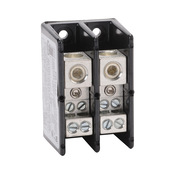
Distribution block:
m_pb1042.jpg


'da Kid

http://www.automationdirect.com/adc...,_UL_Recognized,_175A-760A_(PB_Series)/PB1042
 
The10mmKid said:
Almost there! Rad, you may need some heavy terminal blocks for the 60A feed/split. I don't see two #4 wires fitting into the first 30A DIN mounted breaker . . . could be wrong. The terminal blocks are cheap. Rad, P-J, I have a real concern and years of experience with SSR's failing. Usually shorting 'ON'. May not happen in our low usage environment at home, yet we are also not purchasing 'top-of-line' SSR's nor are we dissipating heat as efficiently. P-J, would you favor Rad going back to your GFCI E-Stop trip circuit now that the power and control are separate? An E-Stop on each panel. Looks good Rad, 'da Kid

Hey Kid,
I have do have intentions of using distribution blocks for splitting the 60a feeds to their 30a DIN breakers. I'll make that revision on the final draft, Thanks for the reminder. Actually, I might just get the ones you posted.
As for the SSRs failing, does it matter since the E-stop it opening the contactors not the SSRs, unless that's what you meant?

As for the "Almost there", I agree!!! I feel like so long as the circuits look correct, I'm about one revision away from the final draft. P-J really helped me wrap my head around it, then I was able to pick it up from there. I'm still no P-J.

You guys have been a great help.
Thanks.

Many designs put a two-pole, normally open contactor before each element, run both hot lines through it, and put an on/off switch on the panel, to control the contactor coil. It allows you to use a switch to know that "off means off," even if the contactor fails in the closed position. It's a very reasonable additional safety margin.
 
jeffmeh said:
Many designs put a two-pole, normally open contactor before each element, run both hot lines through it, and put an on/off switch on the panel, to control the contactor coil. It allows you to use a switch to know that "off means off," even if the contactor fails in the closed position. It's a very reasonable additional safety margin.

They are already in the design. I'm not using the leak current GFCI method. Thanks
 
Hey Kid,
I have do have intentions of using distribution blocks for splitting the 60a feeds to their 30a DIN breakers. I'll make that revision on the final draft, Thanks for the reminder. Actually, I might just get the ones you posted.
As for the SSRs failing, does it matter since the E-stop it opening the contactors not the SSRs, unless that's what you meant?

As for the "Almost there", I agree!!! I feel like so long as the circuits look correct, I'm about one revision away from the final draft. P-J really helped me wrap my head around it, then I was able to pick it up from there. I'm still no P-J.

You guys have been a great help.
Thanks.

We're on the same page, just a different paragraph. :)
I wasn't sure if you intended to E-Stop the entire system or do each panel independently. The circuit as drawn will open the heater contactors, so you're good for stopping an overtemp fault condition.

Some other thoughts:
Dont make your panels so tight you can't comfortably work in them. There will be situations where you may be working around live circuits inside.

Use multi strand wire in the cabinet. A lot easier to work with. MTW is what we like to use. You'll probably be bringing THHN over from the main panel, but that crap is stiff.

Find out also about dissipating the heat from the SSR's. You have a lot of VA (watts) rushing through there. We don't design and build many panels at work, but sure work in many.

Can't think of anything else at the moment,
'da Kid
 
They are already in the design. I'm not using the leak current GFCI method. Thanks

Indeed it is. Your PID Power switch cuts power to the PIDs and all of the elements through contactors. Very nice. Carry on. :)
 
Back
Top