3 Kettle, 3 Pump Automated-Capable E-HERMS Build

Homebrew Talk - Beer, Wine, Mead, & Cider Brewing Discussion Forum

Help Support Homebrew Talk - Beer, Wine, Mead, & Cider Brewing Discussion Forum:

This site may earn a commission from merchant affiliate links, including eBay, Amazon, and others.

mliptack

Well-Known Member
Joined
Dec 27, 2011
Messages
138
Reaction score
8
Location
Milwaukee
Full Disclosure:
This will not be an ‘overnight’ build – in fact, this build is already about 2-3 years in the making, mostly idle time, and may very well take another year to complete (but lets be honest, is any brew system ever “complete”?)

My intent is that is build will help others learn from my mistakes, and hopefully those that have been down this path that I am about to venture, can help me prevent making the same mistakes they have made.

If it’s worth doing, it’s worth overdoing.​

This post will be centered around what I plan on doing and what I have already done. I then plan on posting what my next steps will be.

Current System:
AG / Gravity fed / 5.5-6gal to fermenter
7.5gal Kettle used for HLT
Gott Cooler Used for MLT
15gal Kettle used for BK
Banjo Propane Burner (or Stovetop if its too cold)


The problem:
Safety: Like many homebrewers I routinely lift heavy kettles full of boiling wort or near boiling water (Including kettle weight ~100lbs pre boil/~85lbs post boil).
Precision and Consistency: I would like to have precision and repeatability of a commercial brewery, specifically with my mash temperatures.
Time: I enjoy homebrewing, but would like to reduce the time commitment, so I have more time to spend with my family or completing other brewing tasks or hobbies.
Cost: When brewing outdoors, my cost per batch increases by about $7-8 per batch in propane costs.

Brewing Needs:
Safety: I need to eliminate the need to move/lift hot liquids and filled kettles. Essentially the only lifting required will be fermenter/serving related.
Quality: I want predictable & repeatable results, eliminating much of the variation caused by the Human Element.
Time: I want to be able to manually operate the system when my time allows, but I would also like to automate the system when I do not have the time to commit (or don’t want to brave the cold for extended periods of time)
Cost: I would like to keep my brewing costs relatively consistent regardless of where I am brewing.
Curveball: I would like to begin brewing remotely (From bed early in the AM, or from work if brewing in the PM).

End Goal:
Network Connected & Controllable Single Tier, 3 Kettle, 3 pump, Electric HERMS Brewery.

Credits: Besides the obvious Loving Wife; awesome Boys, Family, dog… etc., etc.

The design concept comes largely from two sources.
Kal - from the electric brewery. Much of my control panel, heating element and HERMs coil choices were influenced by Kal’s design

JonW - the simplicity (and I use the term loosely) of the 3 pump design comes from JonW’s design. With safety being such a high priority of mine, the cost of a third pump outweighed the potential for injury of mis-handling a hose during an automated step.

I thank you both for your generous contributions to this project. The rest of this project is mostly a product of my brainchild with bits and pieces pulled in from past jobs, experiences or websites/posts that I don’t quite recall. If there is other credit owed, I will do my best to point it out whenever possible. If I lapse and you think I owe you, or someone else, credit, please don’t hesitate to let me know.


Where am I today?:
Control Panel
I have a control panel mostly built. I started with the intent to use the Brewtroller.
I purchased the BT 4.0 Pro system, but after much trial and error, I was never able to reliably connect remotely to the system. Instead I have invested in the BCS Platform. With this system I will be able to remotely turn the full system on and begin brewing. I will have to make a few modifications to the control panel. But the space formerly used for the BT LCD I will likely keep as a ‘window’ to see the inside of the panel.

Kettles - 60 or 80qt Kettles
I purchased the 3 kettles that I will use, they are Winware 60qt/15gals from amazon. Now that I am older and wiser, I should have purchased the 80qt/20gal size.

I have a falsebottom from NorCal brewing.

Thus far I have built 2 - 5500W heating elements almost matching the EB setup. One of the major differences in design is the use of Neutrik’s PowerCon 32 Amp connectors instead of the L6-30 Connectors suggested by Kal’s design. The L6-30s are bulky in my opinion. Plus from the panel design perspective - about 4 of the PowerCon panel mount connections fit in the space of one L6-30 Receptacle - leaving plenty of room to grow!

Neutrik PowerCon - PowerCon 32a Plug

Neutrik PowerCon Socket - PowerCon 32a Socket

Linked for future reference and as a reminder to etch my kettles:
https://byo.com/stories/issue/item/3113-etch-your-kettle-projects

Stand
Not started, but have designed a few solidworks models and junked most of them.


Thats about it for now. Sorry for the novel. Pictures to come soon!

Let me know if you have any questions or suggestions! I look forward to hearing comments!

Thanks,
Max
 
Here are a few images of current state.

The control panel in this image currently has the Brewtroller installed and running.

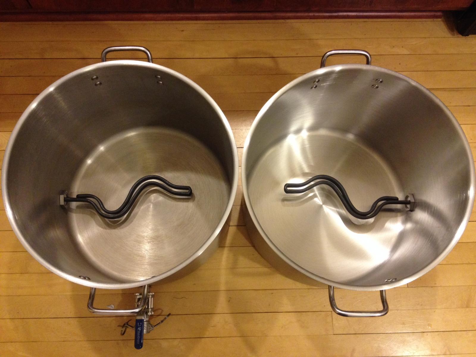
The next two images are of the HLT and the Boil Kettle with the heating elements installed (pictures taken last night). I am currently looking around for a metal fabrication company to bend my 1/2" stainless tubing. Luckily they are plentiful in area, plus I work with many of them through work.

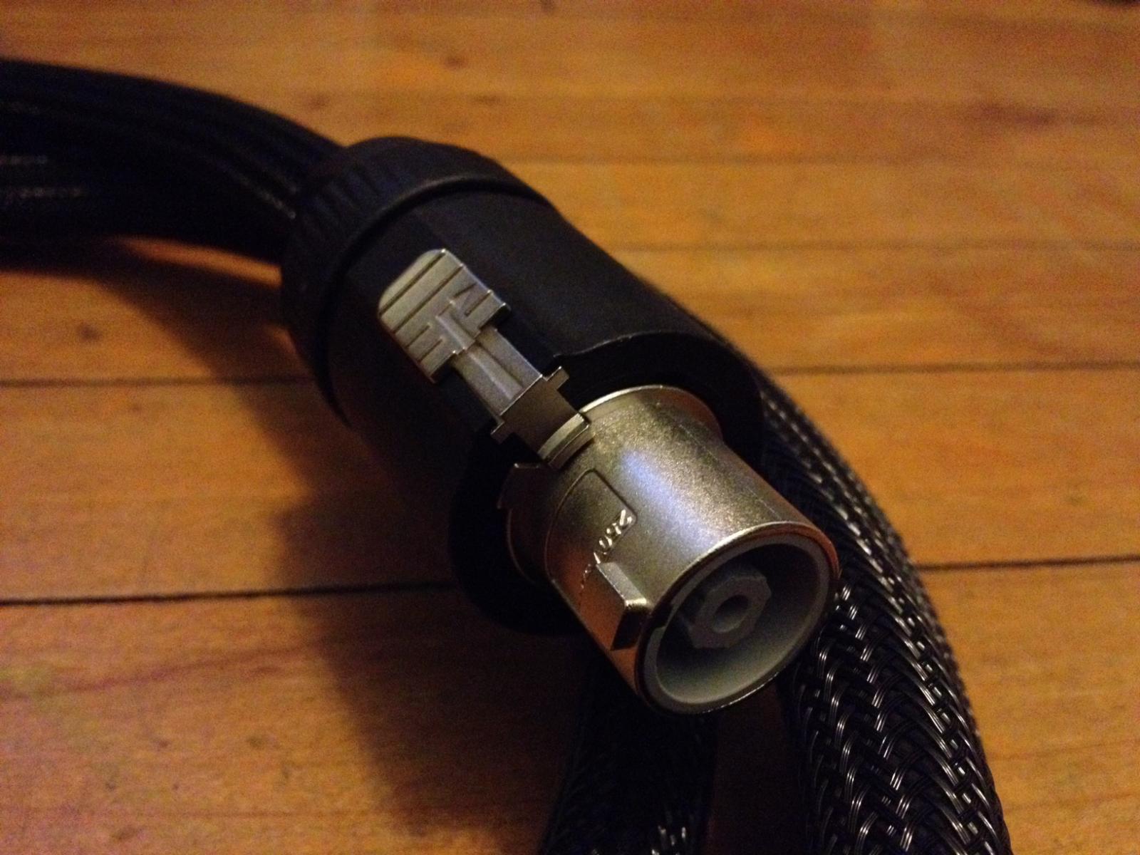
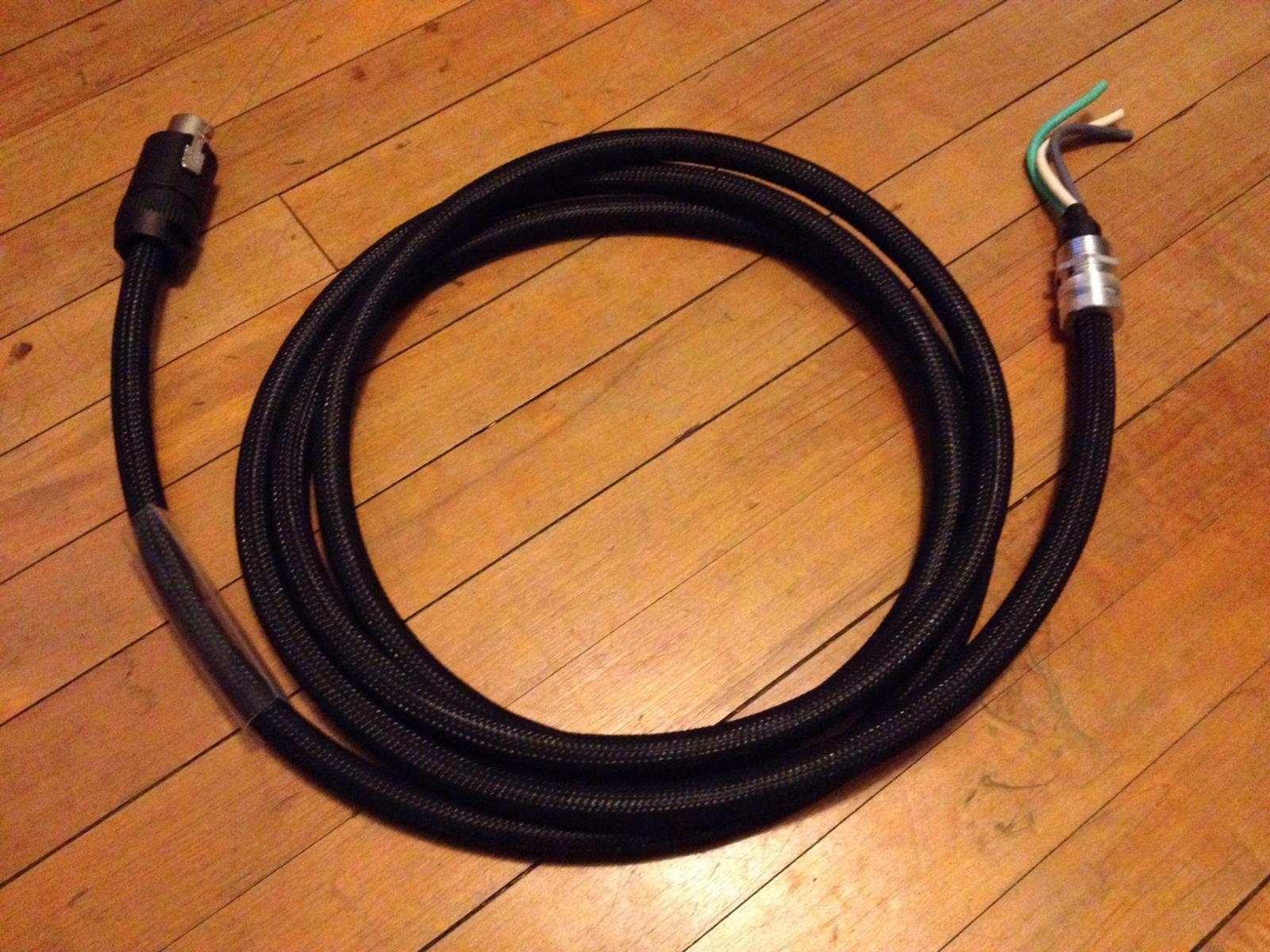
The last 2 pictures are closeups of the heating element pig tails and neutrik 32a male connector. One pigtail is 12' long, the other is 8' long (not pictured). I had them installed in the boxes, but removed them to be able to tighten the heating elements. Notice the heat shrink in place ready for labels.

Today's agenda:
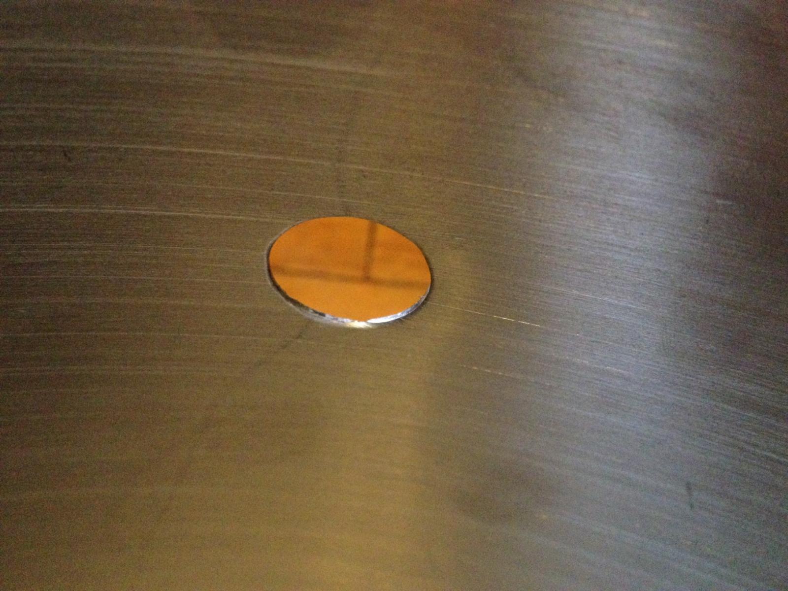
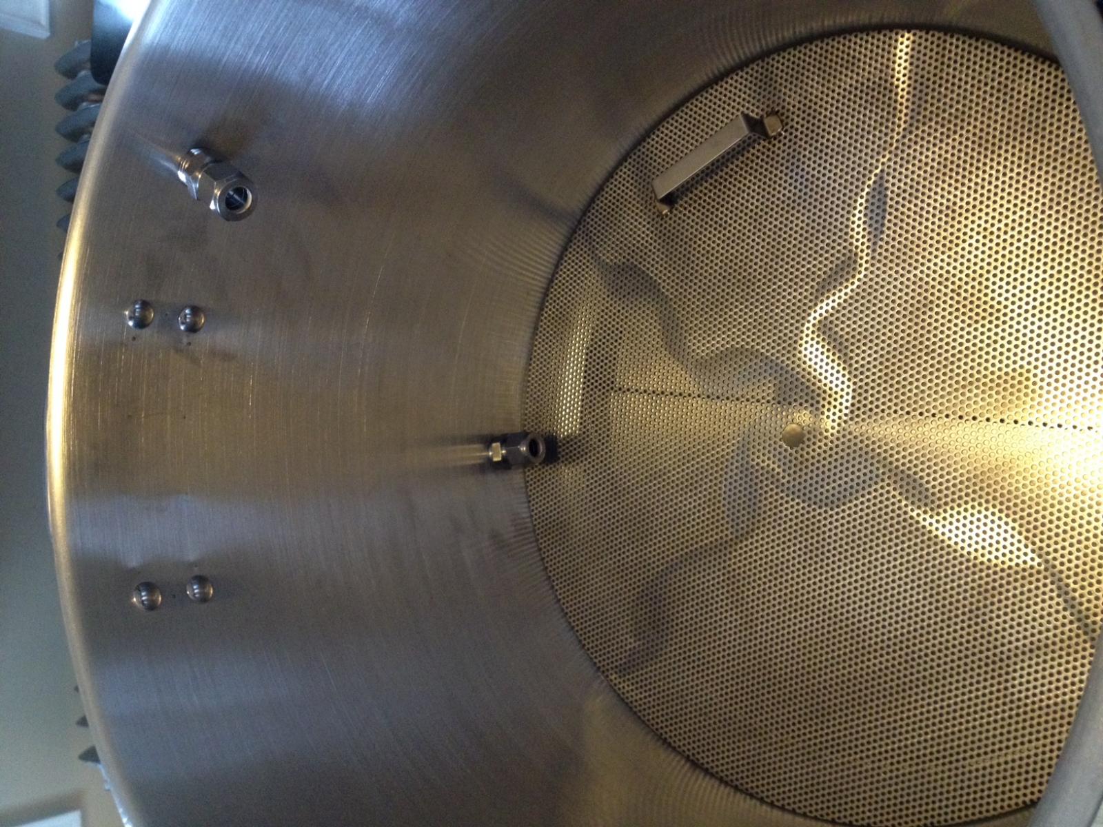
Punch holes for HERMS Coil in HLT
Punch hole for inlet/outlets in HLT, MLT and BK

IMG_0408.jpg


IMG_0872.jpg


IMG_0876.jpg


IMG_0879.jpg


IMG_0878.jpg
 
Last edited:
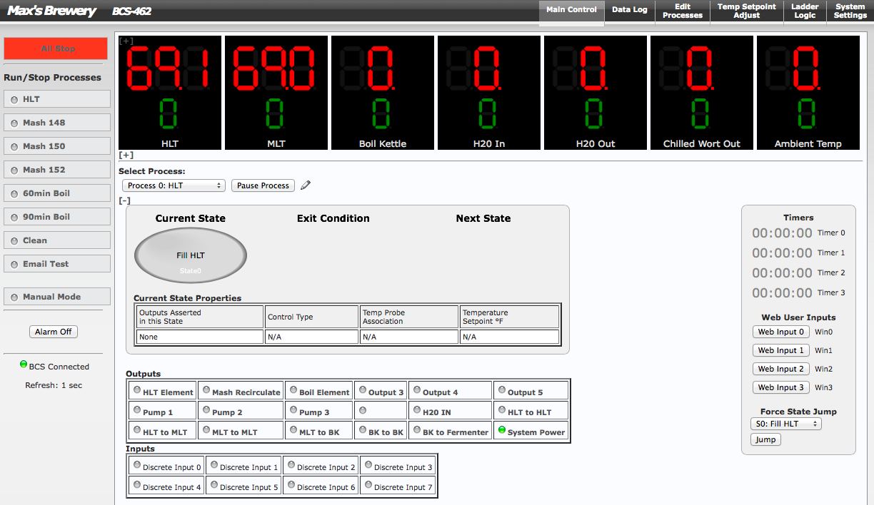
Current BCS view.

Some system configurations in, but mostly stock at the moment until I figure out the full system design.

Screen Shot 2014-12-27 at 8.20.28 AM.png
 
Cool. Have followed some of your question posts here and on ECC forum. Looking forward to seeing progress on your build. It is a couple of steps ahead of my build.
My stand and hardware are 90% done, and if the final 10% takes the usual 90% of build time, control panel is 10% done.
As I recall, you're holding off on 4.0 because you're averaging temp sensors?
 
Thanks for the support guys.

4.0 will likely be on the horizon. I figured I would stick with what came with the BCS first, brew a few batches with it so I can develop an opinion on that version of the firmware. Then make the switch to 4.0 and do the same, hopefully by that point it will be fully released.
 
I would say if you mostly doing 5 or 10 gallon batches you did the right thing going with 15 instead of 20 gallon pots.
I also used similar connectors for my elements only I went with the cheaper brand sold at mouser and regret not going with the ones you have, Mine do not lock at all and can easily be unplugged from the panel.
I am envious of your patience...I jumped in and ended up doing a lot of changes to my setup. In the end I have almost a complete second system.
 
AugieDoggy - Thanks for the kudos, but don't be envious, I am actually rather impatient, the 2-3 year planning was less by choice, more due to a lack of funds allocated to the project and my youngest boy joining the family.

You're probably right about the kettle size. But in retrospect, the extra $10-15 per kettle would have been worth the cost in case I wanted to upgrade down the road. I could have sworn that I bought the 20gal size... that explains why my volumetric readings were always perplexing me (and my efficiency was through the roof!)

The Neutrik Connectors I used at my old job. I used mostly the 20amp size and really liked the build quality, they can really take a beating. I figured it made the most sense to use them. I will be using the 20amp versions for the pumps on this system.

Thanks,
Max
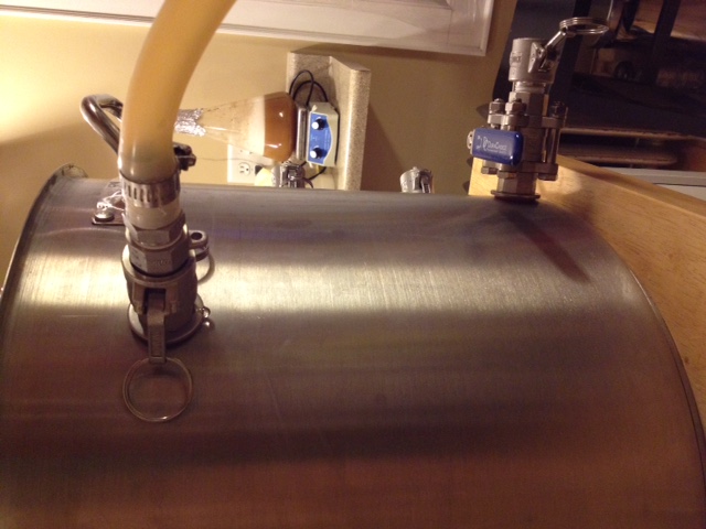
 
Thought I had enough stainless hardware - looks like I'll need more. Mostly Shims and Locknuts.

Here are a few pictures I took while working on it today

IMG_0885.jpg


IMG_0882.jpg


IMG_0886.jpg


IMG_0881.jpg


IMG_0893.jpg


FullSizeRender.jpg


IMG_0889.jpg


IMG_0891.jpg


IMG_0890.jpg
 
Subscribed, good luck! I'm piecing together my BCS build now. Using kegs instead of kettles and bottom draining the 3 of them.
 
Just curious - but why did you mount the female camlock connectors on your 3-way valves? Probably doesn't matter, but curious if you had a reason.
P
 
carpenike - I eventually would like to drain from the bottom - I plan on learning how to tig weld so I can make more advanced modifications like that to my kettles.

Plove - The Cam-Locks were to be able to simply remove the hoses after brewing to allow them to fully dry. I guess it would probably be easier to connect if the male cam lock was on the valve end instead... do you suggest I do something differently? I am all ears :)

Cheers,
Max
 
So I have been playing around to find the best universal configuration for the weldless fittings.

Since most of the connections include the camlocks (and these are a pain to tighten all the way down) I have been using the following sequence

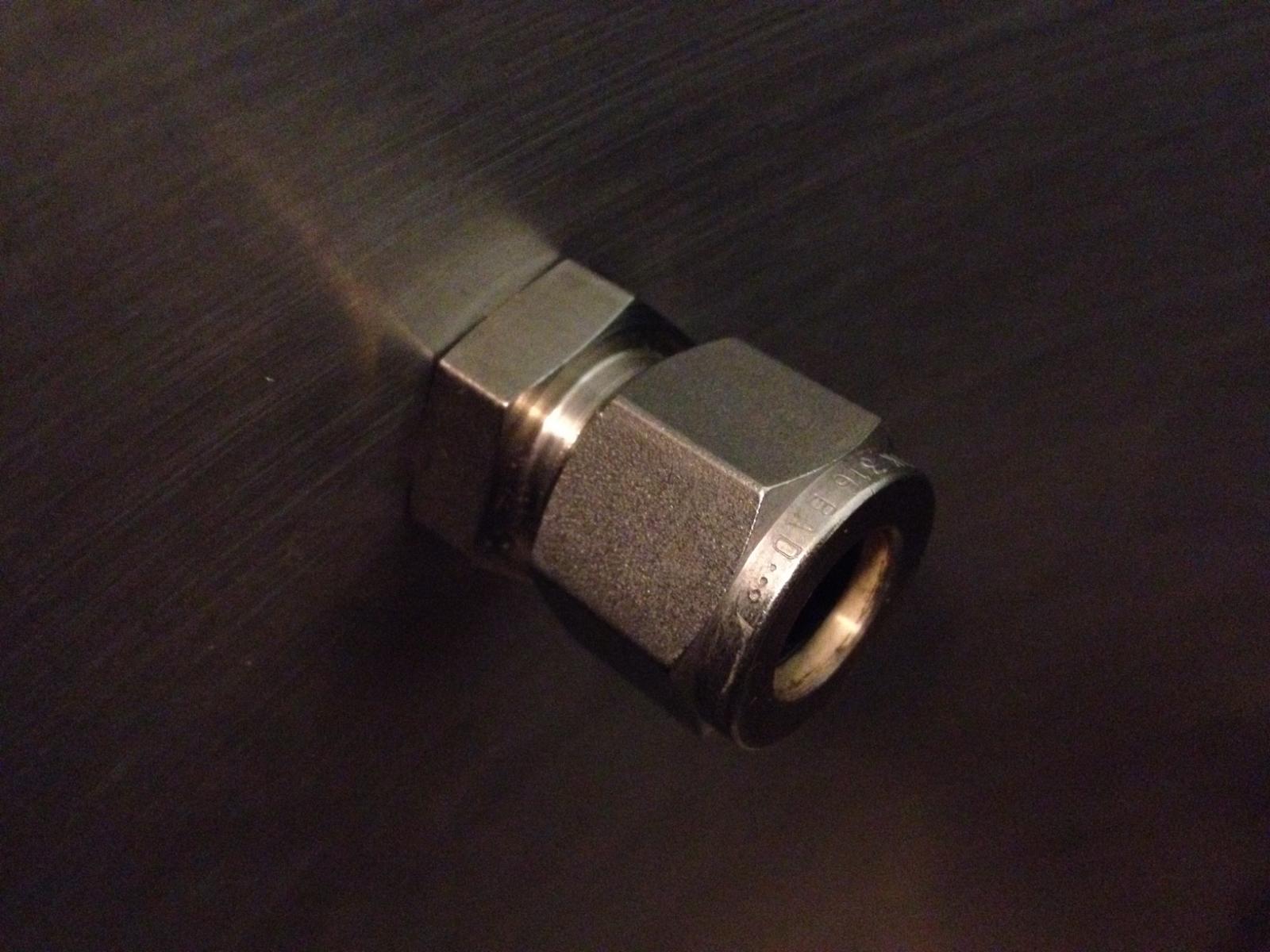
Cam lock (female) - 1/2" Locknut - Silicone Washer | kettle wall | - 1/2" NPT Male to compression fitting

The Compression adaptor is locked in place and sealed independently of the cam-lock. While I don't foresee the need to ever remove the cam-locks this would allow me to remove it without removing the compression fitting.

How do others typically do this? Any recommendations or suggestions?


Today I ordered DIN rail, terminal blocks, and breakers for my panel so I can start to rebuild in the areas that need some work. I will also try to draw out a schematic and share that.
 
Plove - The Cam-Locks were to be able to simply remove the hoses after brewing to allow them to fully dry. I guess it would probably be easier to connect if the male cam lock was on the valve end instead... do you suggest I do something differently? I am all ears :)

Cheers,
Max

I would put the male side on any component that will get hot. You may not plan on ever having to swap hoses while brewing but the day will come when its necessary and its not fun to grab a very hot female camlock and try to lock it, same goes for the QD's, its better to put the male side on the hot components for easy assembly/disassembly while the brew session is in full swing
 
Ryane - Never thought about that - you make a good point. I have brewed on a burner with the same configuration for a while and haven't noticed it to be too hot to touch (yet).

Maybe it will be a problem with the Herms In/Out and Inlets on the top of all the kettles since they won't be 'insulated' by the ball valve. I will certainly keep that in mind. I don't think I would be able to swap the configuration without reinvesting in hardware - when running tests on the system I will have to check their temperatures.

Thanks for the suggestion! Keep them coming.


Today's Agenda:
Work on the kettles is at a standstill until I get my other locknuts and misc hardware that I will need.
Planning on working to configure the BCS a little more and fully plan out my plumbing and wiring schematic. This might take a while...
If I get tired of starring at the drawing board I might mount my BCS in the control panel and get a little bit of basic wiring done. Maybe punch holes for the Heating elements and pumps.
 
So my youngest son and I are sick, so I spent more time sleeping or caring for him than working on the system.

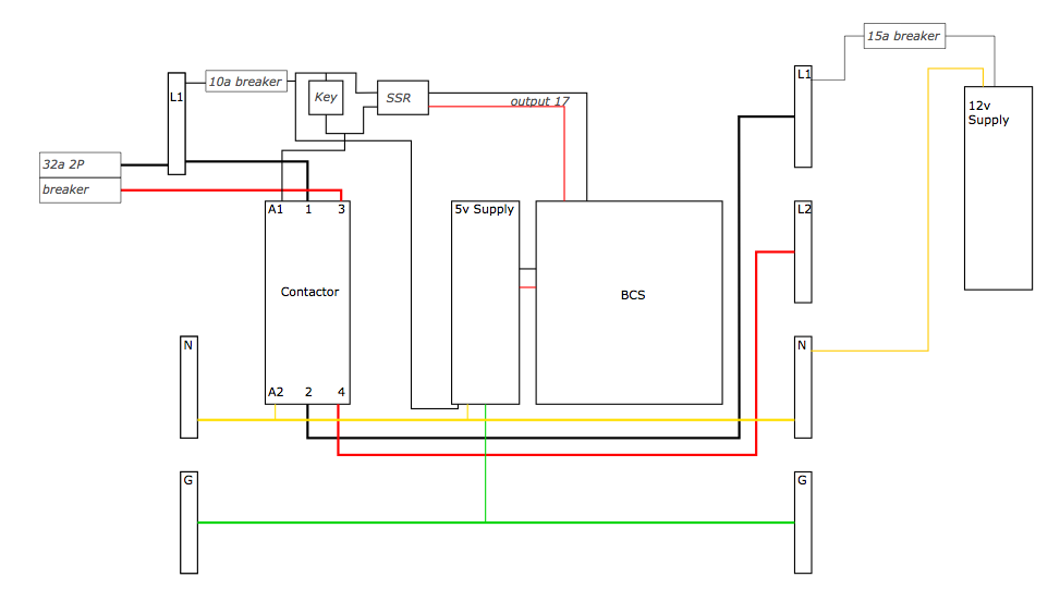
That said, here's the beginning of the panel schematic - looking for anything glaring that I may have overlooked.

Note: lines crossed at 90deg are not connected. Lines that form a "T" are connected.

Design considerations:
  • BCS & 5v Supply will always be on even if the keyswitch is off. This will allow for remote programming without having to fire up the system.
  • System has key switch to power up, but can also be triggered by turning on output 17 from the BCS. Key switch will be labeled with "Auto" or "On" as switch options. Both key and Out17 will provide 120v to a contactor for the rest of the panel.

Something I need to consider, that I haven't completely thought through yet is to someway safeguard against dry firing anything. For example, lets say I was working on programming the BCS at work, and was testing a program that recirculated the HLT pump and had the HLT element on. I leave work and come home and want to brew. I flip the key switch and the HLT element and pump start running.

I'm thinking that if I set up a NO relay directly to the 12v supply, and connect it to a discrete input to the BCS, and program that input to stop all processes. Upon power up, the 12v relay would Close and send a signal to shut off anything that was running. I am not even sure this would work/if the BCS is capable of it.

Is there a simple solution I am overlooking? Besides telling me to make sure I stop the processes before I turn the switch :)

Cheers!

Screen Shot 2014-12-28 at 8.47.36 PM.png
 
So my youngest son and I are sick, so I spent more time sleeping or caring for him than working on the system.

That said, here's the beginning of the panel schematic - looking for anything glaring that I may have overlooked.

Note: lines crossed at 90deg are not connected. Lines that form a "T" are connected.

Design considerations:
  • BCS & 5v Supply will always be on even if the keyswitch is off. This will allow for remote programming without having to fire up the system.
  • System has key switch to power up, but can also be triggered by turning on output 17 from the BCS. Key switch will be labeled with "Auto" or "On" as switch options. Both key and Out17 will provide 120v to a contactor for the rest of the panel.

Something I need to consider, that I haven't completely thought through yet is to someway safeguard against dry firing anything. For example, lets say I was working on programming the BCS at work, and was testing a program that recirculated the HLT pump and had the HLT element on. I leave work and come home and want to brew. I flip the key switch and the HLT element and pump start running.

I'm thinking that if I set up a NO relay directly to the 12v supply, and connect it to a discrete input to the BCS, and program that input to stop all processes. Upon power up, the 12v relay would Close and send a signal to shut off anything that was running. I am not even sure this would work/if the BCS is capable of it.

Is there a simple solution I am overlooking? Besides telling me to make sure I stop the processes before I turn the switch :)

Cheers!
Get a float switch for the kettles with elements. Also tie the pumps to the same float switch to prevent dry pumps.
 
Get a float switch for the kettles with elements. Also tie the pumps to the same float switch to prevent dry pumps.

I probably should go that route. I have considered it in the past but wanted to somehow make it adjustable so I would be able to hit a set level (a pseudo liquid level sensor for automation). I am probably over thinking it.

Any idea where I could find a good (easy to clean - preferably stainless) float valve?

I've been getting most things from Ryan at ebrewsupply. He's great to work with.

http://www.ebrewsupply.com/shop/more/elements/1-2-npt-stainless-steel-float-switch.html
 
Oh cool, thanks for the tip - I just ordered a bunch of DIN Rail stuff from him yesterday, even on a Sunday, he was lightning quick to respond to emails.

Yeah he has been great. I put a big order in with him a few weeks ago and he helped me review it and added things I needed after the fact. Also he was quick to fix an incorrectly shipped part and has responded very quickly to all my many emails. Solid guy.
 
Joined in on a group buy for 1/2" 2-way SS Motorized ball valves today @ $25/each+s&h. Safe up to 100deg C.

Now I SHOULD have about 95% of the components needed/ordered:
Still Need 3 Pumps (probably some SS 1/2" nipples and some more SS Compression fittings to connect it all together)
Probably need a new 16ch relay board. The one I had leftover from the brew troller currently is not working with the BCS.

The end of 3 years of planning is in sight... and my tiny home office is a mess!
 
Still sick today and still helping take care of the boys. So I am not making much progress in the Brewery Domain...

Bought a relay board that should work with the BCS - http://www.dx.com/p/16-channel-5v-relay-module-board-red-blue-238261#.VKDgHAVCs

Needs 5v Supply - Check
Needs 5v Trigger - Check
Needs >5ma - Check

At $24 shipped, if it doesn't work it won't be much of a loss.

Schematics:
Plumbing This one is mostly done. I'm not going to share it here, because its hand drawn and almost identical to JonWs design. The only differences; 1) It adds another Valve for water in; 2) The mash tun recirculating line goes first to the rims system then to the MLT.

Electrical No progress since yesterday. I am going to redraw them in visio so they are a bit more clear with the ways the lines are ran. With the help of Ryan over at ebrewsupply.com, he has sent me a few of his schematics, so I can use his objects library.

I will post some images once I make some more progress.

Cheers!
Max
 
User Poll: What connectors should I use for my Valves?

I am already using 3 Pin XLR for my Temp Probes, and I would prefer to eliminate the possibility of accidentally plugging a temp probe into a pump outlet.

4-pin XLR?
Other suggestions? Looking for small footprint and low profile.

Cheers!
Max
 
Wiring Schematic is ~90% Finished - see attached PDF :rockin:

As noted on the schematic - I give a huge thanks to Ryan at www.eBrewsupply.com he provided me with a few of his Visio drawings. A few of his custom objects and a baseline for wiring significantly reduced the amount of time it took to design this.
Cheers Ryan! :mug:
All else is the product of my bed-ridden sickness (Powercon, XLR, relays)

I would like to make this as safe as possible - and after staring at it for about 2 days, I am sure I have overlooked something. The wiring schematic is of my own design and am braced for any and all criticism/comments/recommendations! CodeRage - Have at it.

Schematic related To Do list:
  • Finish up the relay and the devices it will control (pumps, valves, alarm buzzer etc.)
  • Wire in Float Switches for HLT & Boil Kettle Element protection (consider adding a 3rd for HLT fill level)
  • I am sure there is more...

I will likely make a few changes (noted in the Notes section), including the addition of a Case Door Interlock. The interlock would shut down the main contactor if the door is opened to reduce the amount of line voltage exposure.

The interlock would also provide a simple means of adding an external E-Stop Button if I ever choose to do so.

That's all she wrote.

Cheers!
Max

View attachment Control Panel Wiring Schematic.pdf
 
sub'd kudos on what looks to be a cool setup and in a cool place none the less (Milwaukee!!). About to make the change over to eHERMS and pretty excited.
 
sub'd kudos on what looks to be a cool setup and in a cool place none the less (Milwaukee!!). About to make the change over to eHERMS and pretty excited.

Thanks Jowag618 - It will be nice to finally get to put it to use. Because I punched my kettles for the heating elements, I won't be able to brew until I can at least fire up the elements manually... That certainly puts a time crunch on my build. I have 2 bags of crushed grains sitting in my office that need to be brewed soon.

Are you in Milwaukee too?


BCS Ladder Logic Question

I am looking at integrating float switches into my HLT and Boil Kettle now.

Because I want them to control multiple elements I will need to wire them as a DIN on the BCS. Ignoring any running processes - lets say I fire the HLT heating element by Asserting Output0 on my BCS main page. But my water level is below the Float Switch.

Question is, what is the best way to do this? I assume I need to use ladder logic - Could someone provide an example of the ladder logic to be able to prevent dry firing?

Thanks in advance! Happy New Year!
Max
 
Because I want them to control multiple elements I will need to wire them as a DIN on the BCS. Ignoring any running processes - lets say I fire the HLT heating element by Asserting Output0 on my BCS main page. But my water level is below the Float Switch.

I would just wire the N/O float switch in series between BCS output and SSR input. Prevents a dry-fire regardless of how/who tries to send power to it.

I just looked over your schematic and wondered the reasoning behind wiring the SSRs on same output in series?
 
I would just wire the N/O float switch in series between BCS output and SSR input. Prevents a dry-fire regardless of how/who tries to send power to it.

That was my initial thought, but I would only be able to use the float for one device, in which case I would need to put 2 floats in each kettle. My thinking is, I would like the same float to kill power to the heating element and the pump. At this point it would require human intervention to run the pump until completion (I am thinking about adding a momentary push button along with the 3-way selector for this).

With the ladder logic, I figured out a way to do it, but it probably is over complicated (and it wastes an output per device I want to have protected)

Example: HLT Heating Element Protect
Rung0 - Out0 (Wasted out) - Float DIN0 - - - - - OUT15 (SSR for Heat Element)

I would trigger Out0 in all my programs etc. and only if DIN0 is closed will it trigger power to the Heating Element. Of course the risk is accidentally triggering Out17 from the Main Control.

I just looked over your schematic and wondered the reasoning behind wiring the SSRs on same output in series?

MrNatural - You are very observant, thank you for taking the time to review the schematic and giving me feedback!

That is more of a remnant from an original design that didn't use a contactor for each element, instead, I would rely solely on the SSRs or the main contactor to kill power to the elements. For safety I decided to add the contactors, but never removed the SSRs from the design, because I already have them mounted to a heatsink in my panel.

Really there's no point in adding the additional heat of the 2 extra SSRs that serve no purpose (other than greater complexity). I think I will leave the 2 extra in place as spares, or for any other purpose that may arise.

Thanks for the questions! Cheers!
Max
 
Joined in on a group buy for 1/2" 2-way SS Motorized ball valves today @ $25/each+s&h. Safe up to 100deg C.

Now I SHOULD have about 95% of the components needed/ordered:
Still Need 3 Pumps (probably some SS 1/2" nipples and some more SS Compression fittings to connect it all together)
Probably need a new 16ch relay board. The one I had leftover from the brew troller currently is not working with the BCS.

The end of 3 years of planning is in sight... and my tiny home office is a mess!

Where did you get the valves?
Thanks!
 
The new brewtroller.com community started a group buy. Not sure what the timeline for ordering will be... but $25 each for a 2way valve is hard to pass up.
 
Quick Update: Got a shipment in from bargain fittings and ebrewsupply today.

Trying to organize my panel in all different configurations to find the best layout. I think I am going to use Cat5 as signal wire to a breakout panel that would have connections for all temp probes, valves and float switches otherwise I foresee too many XLR or similar connections coming from the main panel. Plus its much cheaper to extend a few Cat5 lines than it would be for 20+ XLR/mic cables. This breakout box would be located on my brew stand, while my panel will likely be mounted on the wall of my garage near the breaker box.

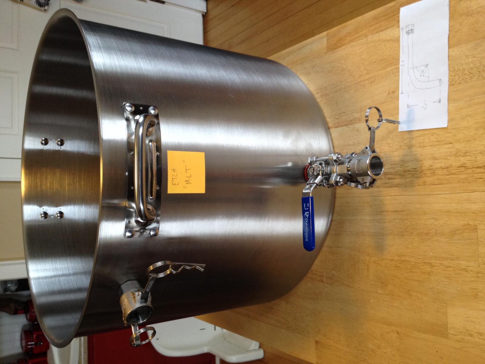
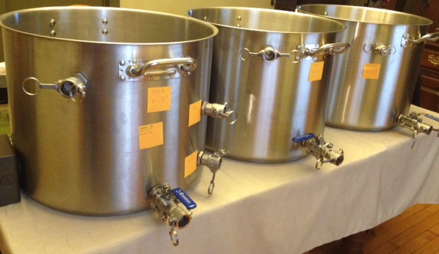
Don't have any pictures of my panel layout to share, but I do have a few of the Kettles.

I have all the holes punched (excluding float valves). Just need to add a bit more plumbers tape to the threads and start to tighten them down. I still need to have some stainless tubing bent for the MLT dip tube, HLT Heat exchanger and for the BK whirlpool arm. I have a 100' spool of it in my basement, waiting.

The dining room table becomes a great place for a mock layout - My wife loves this :p

Cheers,
Max

FullSizeRender-9.jpg


FullSizeRender-8.jpg
 
Today's Update:

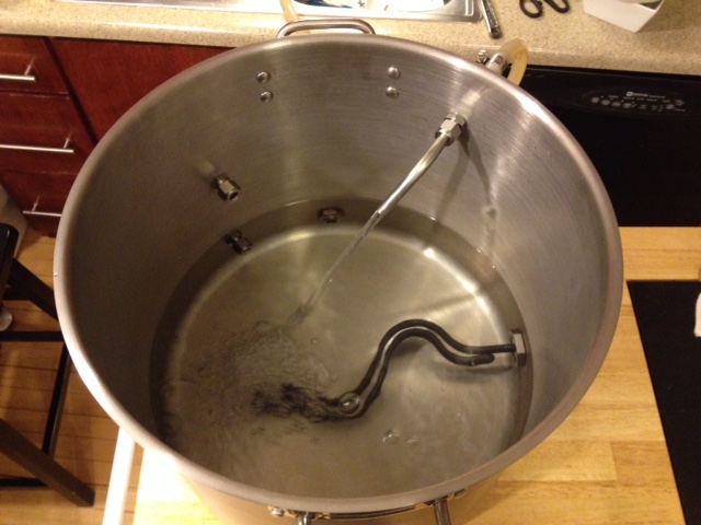
I went out and bought a water heater wrench and tightened down the heating elements in the HLT and Boil kettles. I have about 25lbs of crushed grain that cannot be brewed unless I am able to piece something together (because I don't think I will have the panel done and all three kettles ready to brew with, before the grain starts to get stale).

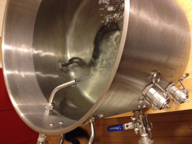
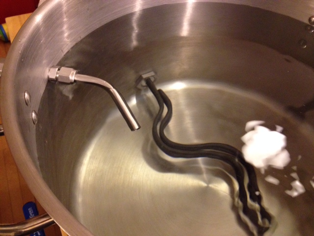
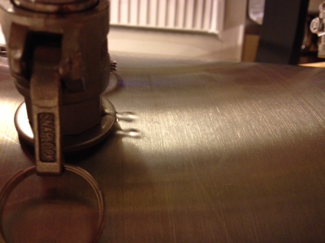
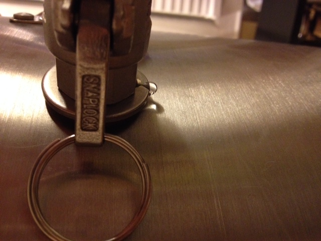
I also added the pipe thread tape and put a wrench to most of the fittings and started a hydro test on the HLT. About 30min in I have 1 leak at the uppermost fitting.

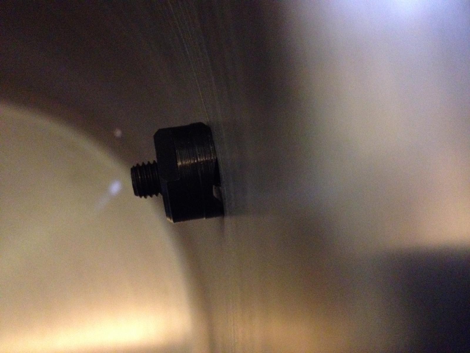
This is the one fitting that the compression adaptor's threads were a little bit smaller, so I opted to use a washer instead of a locknut. This gave me enough length to tighten on the cam lock adaptor. However, I will have to revisit this as it clearly didn't work. I drained some water. The hydro-test continues on the remaining fittings. I'm mostly interested in the heating element.


In the first couple of pictures you will see the kettle filling.

The next couple you will see it leaking from the top weldless fitting.

The final picture you might notice in the background that I have a yeast starter on my stir plate ready for my next brew - One of my favorite yeasts - WLP002

Cheers!
Max

IMG_0989.JPG


IMG_0991.JPG


IMG_0997.JPG


IMG_1003.JPG


IMG_1013.JPG


IMG_1019.JPG


IMG_1025.JPG
 
12hours later (simulating a bad brew day) and the HLT is holding up. So much in fact, that just to satisfy my itch, I may take it for a spin and try to get a batch out today.

I did pull the cam-lock and washer off that top inlet, and replaced the washer with a locknut, as originally planned. Then I added a few more wraps of plumbers tape and tightened down the lock-nut a little further than I usually would, and then added the cam-lock back on. Its holding water now :) Because this spot won't be submerged for very long during the brew day, I won't be testing it for another 12+ hours.

I am going to do the same to my MLT kettle this morning, just because this is the kettle I will use to brew today if I choose to do so. Since it has no heating element and junction box on the outside, I feel more comfortable tossing it on top of a propane burner and cranking it up to 11, without fear of burning the paint off the box.

Since we got a few inches of snow I figure there is nothing better than brewing while shoveling a few inches of snow. My next house I am going to need water/sink and of course heat, in my garage.

Cheers!
Max
 
I posted this in a separate thread, but figured I would bring the images here to keep the majority of the information in one place.

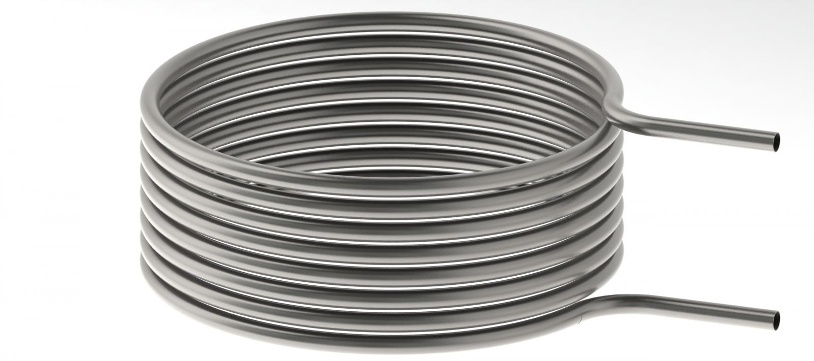
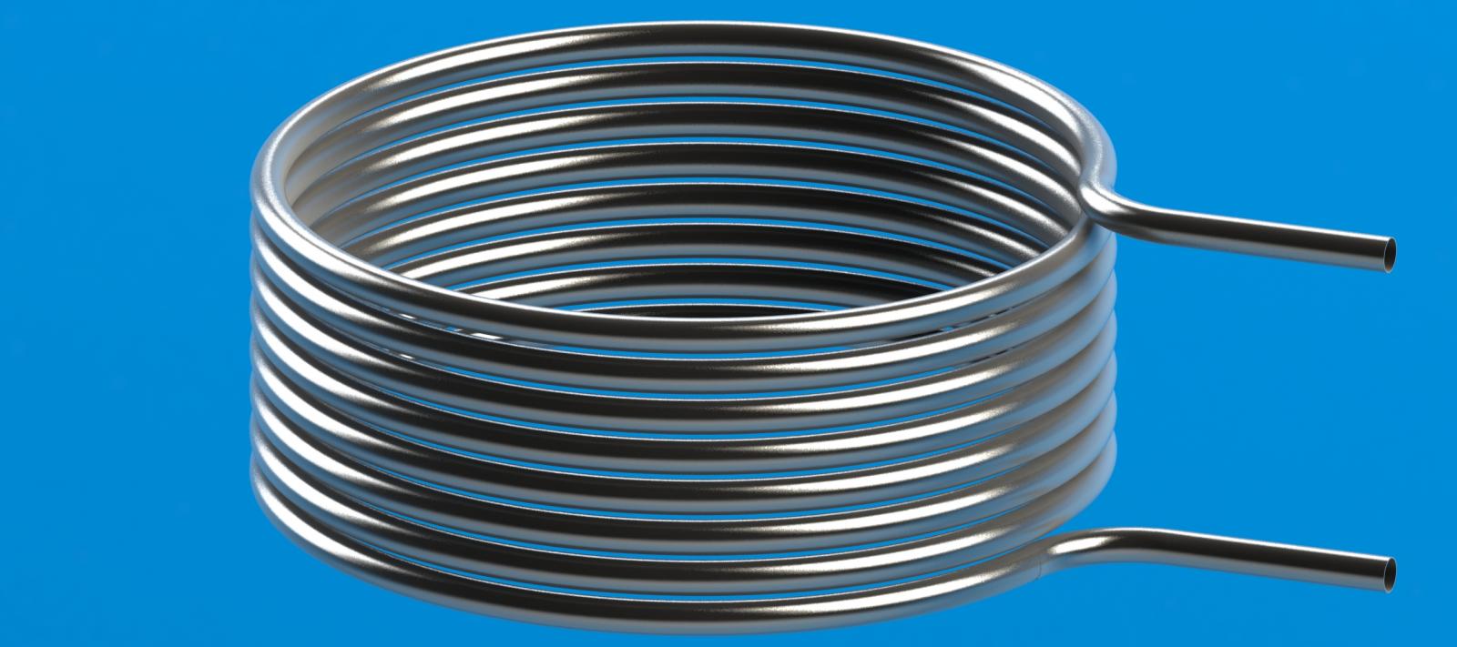
I designed my HERMS coil to be 12.75" OD and 5" tall on center. It ends up being about 30' of SS Tube.

This took me a while to draw up, the hardest part was making the in and out posts to match at the right angle to the tangent (if that makes sense).

I cheated a little bit, and a keen observer may be able to see where both in the renderings and the drawings.

Here's the other thread:
https://www.homebrewtalk.com/f11/he...us-1-2-stainless-0-020-wall-thickness-512425/

View attachment Herms Coil Final - Sheet1.pdf

HERMS Coil Render Final White background.jpg


HERMS Coil Render Final.jpg
 
Back
Top