wyzazz
Well-Known Member
Any updates??

I am actually working on another system right now for HBT member SuperiorBrew. That has taken over all my project time... sorry.
I will have some very sexy pictures of that build soon though... It will be a DITCHES brewery.
 Can't wait to see the pics!


Ok I copied the 2p-Ewent-E control box almost verbatim. Everything was going along swimmingly, got 3-4 brews under my belt with the box. Last weekend had a brew day lined up got everything measured out ready to rock and bam no power to the rims element. Scoured through all the wiring nothings changed ok looks good. Took off the jumpers and pid settings to trigger the alarms to kill the element power just to simplify. Maybe that's crossing up somehow, no go still no power. Must be the ssr is shot. Yeah that's it. Order a new ssr from Aubers got here today wired it up no go...AAAAARRRRRGGGGGHHHH.
Ideas, things to check? I got two grain bills from BrewMasters Warehouse sitting in my fermentation chamber, crushed, and I want(need to get this problem solved. Any help is most appreciated
We never wired the SSR output like you did. There seems two potential problems. 1) if the diode has a low break down potential , the 240 V will be added to the internal transistor and damage it. 2) the output of the SSR control has only limited capacity. It might not be able to drive the diode you have.
Here is how the SSR control output design.
The output driver is a 9013 transistor with a 200 ohm current limit resistor. The power to the transistor is 9V, not 12 V. The open circuit of the output is 8V, not 12V. If your load resistance is 200 ohm, the output will drop to 4V due to the internal current limit resistor.
I hope that helps.
With the wall transformer the ssr triggered and powered the element outlet.If anything, just disconnect the PID completely and use a wall transformer power supply to trigger the SSR. If the element turns on, the problem is on the DC side.
Did this and no go. This time there was no ouput power reading from the multi-meter coming from the PID to the SSRAttach the PID back but straight to the SSR control line, if it has a manual function use that to turn it on. If that works take one more step closer to the final wiring.
Not familiar with a 5.6k pull down resistor is. This would be used on which side of the SSR? The power side coming from the PID or the output side coming out of the SSR to the element outlet?The DIM Led sounds like something is floating, perhaps a 5.6k pull down resistor across the + and - terminals of the relay would fix this.
I completely elemented the breaking of the + with the alarm. Both in the wiring and the setting in the PID. Same problems still exist.I am guessing that breaking the + side with the alarm contact has something to do with this. Doesn't explain where the potential is coming from though.
I agree. Any chance of getting a parts list of connectors, receptacles and the mesh wrap you used?POWER!
These are the cords I built for power in and element power. 12AWG stranded, protected with PET weave, heat shrunk ends, and 20 amp plugs.
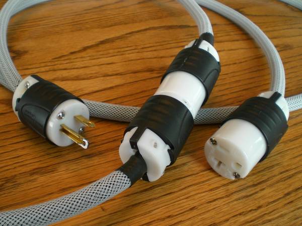
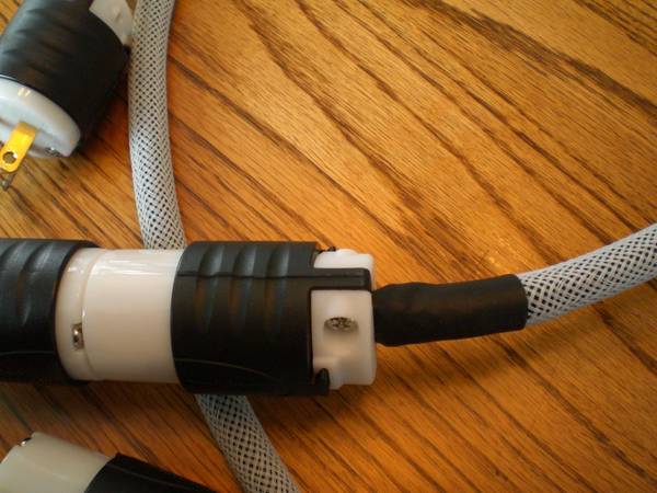
sexy....


![Craft A Brew - Safale BE-256 Yeast - Fermentis - Belgian Ale Dry Yeast - For Belgian & Strong Ales - Ingredients for Home Brewing - Beer Making Supplies - [3 Pack]](https://m.media-amazon.com/images/I/51bcKEwQmWL._SL500_.jpg)


