• Please visit and share your knowledge at our sister communities:
  • If you have not, please join our official Homebrewing Facebook Group!

    Homebrewing Facebook Group

110v Recirculating eBIAB 2.5 gallon batches

Homebrew Talk

Help Support Homebrew Talk:

This site may earn a commission from merchant affiliate links, including eBay, Amazon, and others.
question for jrb03 and anyone recirculating BIAB what are you using below the bag?
ie false bottom or hop stopper
I tried a microwave rack supporting my bag and my bazooka hop stopper on my trial setup ,but wonder what I need for my 70 litre pot I am building.
I dont have a steamer basket so would need something to support the bag

thanks in advance Paul
 
My bag pretty much sits on the element and I don't really use anything to support it. I don't now if this is because of the dimensions of my bag but I do need to lift it up a bit to keep it from getting suck up to the SS Elbow I use for a diptube which will restrict liquid incoming to the pump. All I need to do for that though is pull the bag up a bit and put the lid on, works fine!
 
thanks inhouse brew doea this mean your hops pass through the pump or do you use a hop bag or reuse the grain bag?

Well, I use a plate chiller so I need to be extra careful about hops. I've tried a couple batches just tossing them in there and trying to do a ghetto whirlpool by just stirring the wort and letting it settle which worked ok. I think however I'm going to go back to the hop bag.

Last time I used a bag for boiling hops it got really nasty and clogged up after a bunch of uses. You could lift it up and it would hold wort which would slowly seep out. Not sure if it was the type of bag I used but I'm going to get a new one specifically for hops just to make sure I don't ruin my BIAB bag.
 
My bag touches and rests on the element. I use a hop bag since I use a plate chiller.
 
thanks guys ,I too have a plate chiller and that is why I asked the question.I noticed several people using just a pickup tube in there pot and wondered about the hops in the pump etc.Up to now I have used a bazooka hop filter in my boiler( 5 gallon ,3 vessel setup) and false bottom in the mash tun.However wanting to make a recirculating BIAB 10 gallon, I was wondering what was best considering wort flow during recirculation of mash.
I normally recirculate/whirlpool for the last 10 minutes of the boil to sterilise chiller and was not sure what to go for in the new setup.I think the hop stopper will be the first thing to try as I already have it ,as long as it doesnt clog with hops(bearing in mind I will be doubling my brew length and therefore amount of hops compared with the 3 vessel kit)failing that maybe the hop bag.
 
jrb03 said:
My bag touches and rests on the element. I use a hop bag since I use a plate chiller.

You use the Lowe's paint strainer bags, right? Going to brew the first 1.080+ beer on the system next weekend and I noticed with the basket, the mash gets thick with more than 6 #'s.
 
Finally finished wiring this guy up. Will do a water test this week.


602918_10151635476086102_2118098334_n.jpg


774813_10151635476081102_516152117_o.jpg


774813_10151635476091102_1144515118_o.jpg
 
It pleases me a great deal that I could help you in your adventure.

Regarding the wire: You will need #12 wire for the power being delivered to the SSR and the heating element. The pump outlet wire should be #14. All of the balance of the wiring can done with much smaller wire gauge as the current draw is very small.

Please feel free to ask any questions that you might have.

Oh: Another benefit of this set up is that it can very easily be converted to a 240V BIAB setup. Think about that and if you would like a plan for that for your future adventures, Please let me know.

Wishing you great success.

P-J

I apologize if I have missed it. The many panel pictures are hard to distinguish the wire sizes. I have not seen any mention of the wire sizes used in the many panel builds. P-J indicated that only the wire to the element outlet and the contact and I assume the SSR # 1 & 2 need to be 12 gauge and the pump outlet wire 14 gauge. Am I correct in that assumption ?
Also the remaining wire to the rest of the switches can be what smaller gauge ? All 22 as Kal indicates or do most of you use larger sizes than his . I would appreciate any help before I get to wiring.
 
jbnla said:
I apologize if I have missed it. The many panel pictures are hard to distinguish the wire sizes. I have not seen any mention of the wire sizes used in the many panel builds. P-J indicated that only the wire to the element outlet and the contact and I assume the SSR # 1 & 2 need to be 12 gauge and the pump outlet wire 14 gauge. Am I correct in that assumption ?
Also the remaining wire to the rest of the switches can be what smaller gauge ? All 22 as Kal indicates or do most of you use larger sizes than his . I would appreciate any help before I get to wiring.

Wire size depends on the amps that will be flowing through it. If your setup is being powered buy a 20a circuit then all wires that will be drawing that(contactor, element, ssr) should be 12g wire. The wires going to the pid and pump can be smaller 14g. For example my setup uses 30a so the ssr to contactor to element run 10g, 14g to the pid and pump with a 1a and 10a fuse used. I think using 22g is only for connecting the pid to the ssr but not necessary. I would stick with 12g for 20a and 14g for everything else. IMO
Hope this helps. Keep asking questions for anything your unsure of.
 
Thanks for the quick reply. I am trying to understand the wire size in relation to the fuses that you mention. Couldn't the wire on the down side on a one amp fuse be very small in relation to 14g and the same for a 10a could be maybe 16g safely ? I realize that for convenience all wire could be the same as long as it is larger than needed. Also on the plans that P-J posted for the OP build only shows two 1 amp fuses for E-stop and PID. Did you fuse the 10a pushbutton switches. Did you follow a different plan or do your own ?
 
jbnla said:
Thanks for the quick reply. I am trying to understand the wire size in relation to the fuses that you mention. Couldn't the wire on the down side on a one amp fuse be very small in relation to 14g and the same for a 10a could be maybe 16g safely ? I realize that for convenience all wire could be the same as long as it is larger than needed. Also on the plans that P-J posted for the OP build only shows two 1 amp fuses for E-stop and PID. Did you fuse the 10a pushbutton switches. Did you follow a different plan or do your own ?

Instead of taking over this thread here's a link to my setup.
https://www.homebrewtalk.com/f170/different-e-brewery-380514/
I'll be happy to answer any questions about it there.
 
Wagon_6 said:
You use the Lowe's paint strainer bags, right? Going to brew the first 1.080+ beer on the system next weekend and I noticed with the basket, the mash gets thick with more than 6 #'s.

Correct, I use the paint strainer bags from lowes.
 
Quick question for the pros...

This weekend at Home Depot I was looking at a 12 awg extension cord to "hack up" as has been done here. I find it interesting that right on the box/lable they state it is only approved for 15 amps. However, a minimum amount of research will tell you that 12 awg is approved for up to 20 amps. Any thoughts on this? My 2 cents - attorneys and CYA!
It is rated for 15A due to the Plug & Outlet used on the ends of the cable. The 20A Plug & Outlet have a completely different configuration in their layout.
 
It is rated for 15A due to the Plug & Outlet used on the ends of the cable. The 20A Plug & Outlet have a completely different configuration in their layout.

Paul,

If I understand your response correctly, this would be a no-go for the set-up/diagram you provided in the original post?
 
The cable is A-Ok. It is properly rated for 20A. Regarding the cable plug: This is a picture of a 20A plug. You will see the difference right away.

20A plug:

20A-120V-plug.jpg


Hope this helps.

Edit:
15A plug:
MAR5266CR-LRG.JPG
 
The cable is A-Ok. It is properly rated for 20A. Regarding the cable plug: This is a picture of a 20A plug. You will see the difference right away.

NEMA%205-20P.jpg


Hope this helps.

Yep!

Saw those when I was looking for a 20amp plug...all is clear. As always thanks for sharing your wisdom!
 
jrb, curious as to what size plate chiller you have. I would imagine you don't need a large one for your batch size.

Mine is the duda diesel 10 plate chiller. I would probably go 20 plate if I was to do it again, but only for future consideration. The 10 plate works fine for this batch size and was super cheap.
 
Im using the shirron but thinking of switching to a immersion chiller. Less loss and less mess in the kitchen
 
Great build! I am doing something very similar with these modification. 1) No pump switch as I already have a dedicated pump box. 2) A contactor for main power supply as this is going to be eventually upgraded to 240V and I light have a switch for main power.


With the adjustments mentioned above I have a few questions.

1) Can I connect 2 contactors together to tidy up wiring. What I mean by this is the first contactor will switch main power on. Then, as opposed to have having the power go from contactor 1 to the terminal strip then from the terminal strip to contactor 2 to control the element, can I have to power go from contactor 1 directly to contactor 2 then to the element? (I will also have a 14G wire go from contactor 1 to the terminal strip to power everything else.)

2) I read that on 120V system switching the neutral is not need and does not need to be hooked up to the contractors. Again this would clean up some wiring. Is this true?

3) Does the orientation of the contactors matter as far as line in and out, or does it just depend on how you wire it up?
 
Well I got everything completed and first brew done! I want to give PJ a big thank you for the drawing, it's exactly what I wanted. It was a true joy to brew on this system.

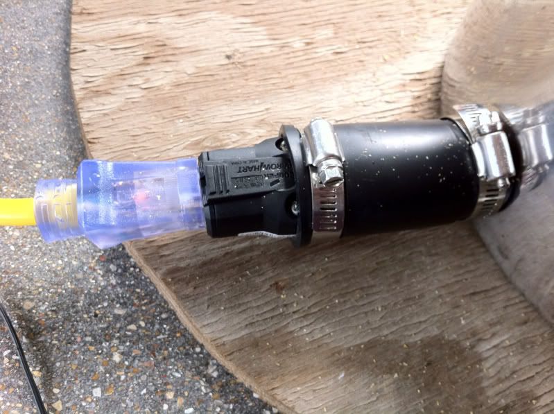
First, I got the element wired up. I decided to try using this 1 1/4" rubber coupling. Other than the weird smell, it seems to work great. I stole this idea somewhere on this forum. I found a male adapter that fits perfect in the coupling. I like the light at the female end of the extension cord I hacked up. Let's me see when the element is on.

cdafca0e.jpg


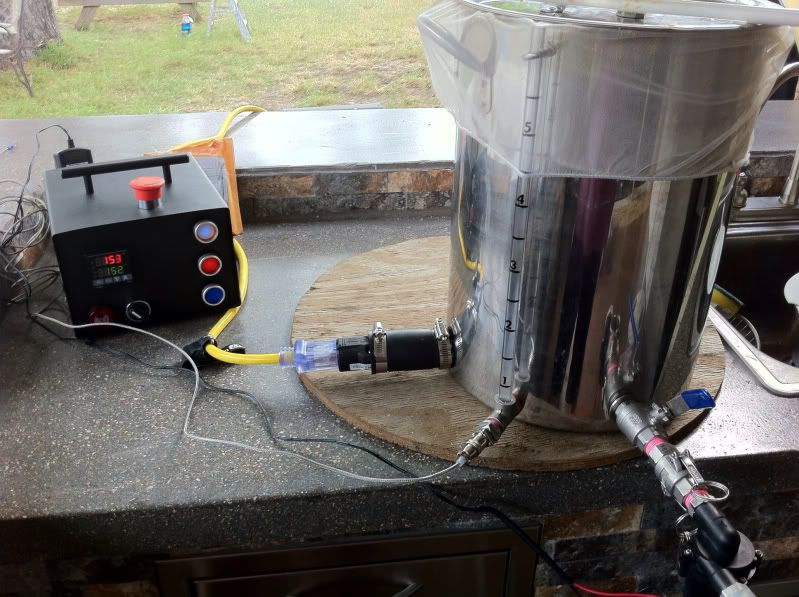
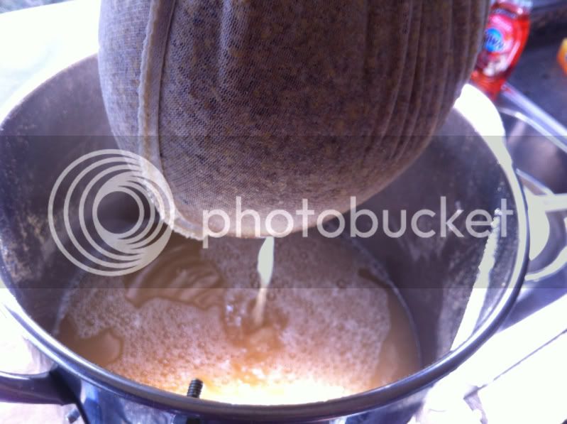
I decided to try BM's Cream of Three Crops for my first brew, sounds perfect for football season. Here is the system setup for mash in.

12a60a16.jpg


The recirculation works great, I overshot my og because I planned for 70% efficiency but got 79%. I also used my ugly junk corona mill for the first time.

7e86a862.jpg

a293b072.jpg

f8727f36.jpg


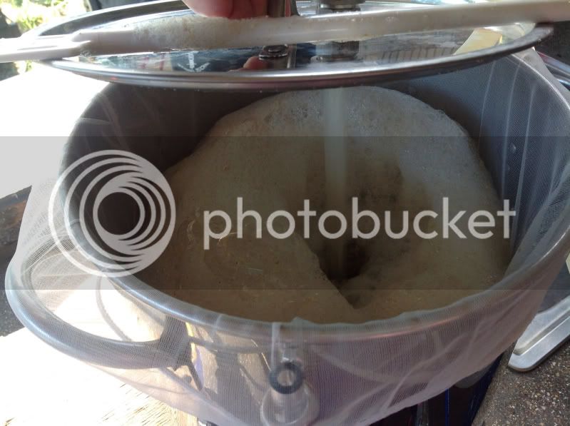
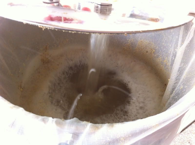
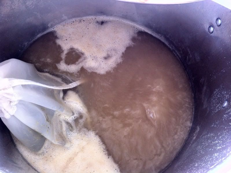
After a 10 min mashout at 170 it took 20 mins to get to a hard rolling boil. I left the PID at 100% manual mode and liked the boil strength for the 3.5 gallons. I boiled off .75 gallon an hour like in my water test last night. I think the 10" diameter pot is keeping the boil off rate low.

c4c28619.jpg


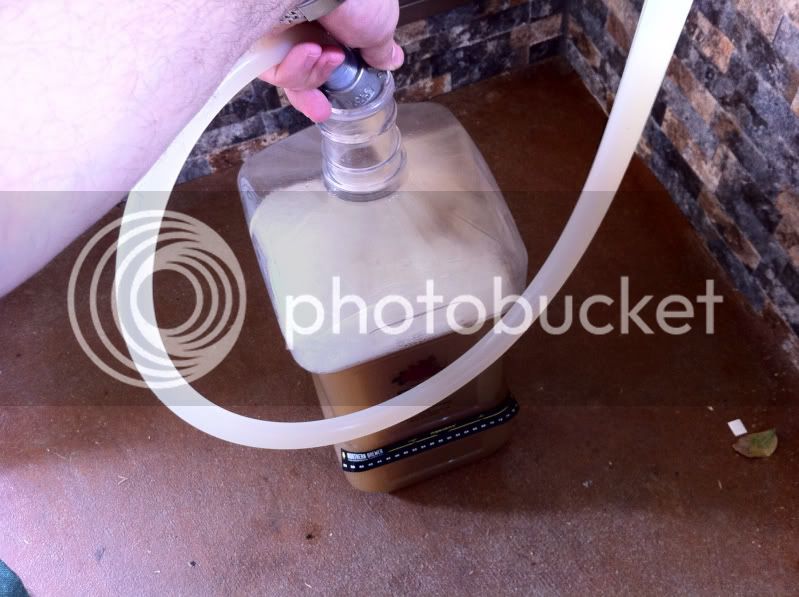
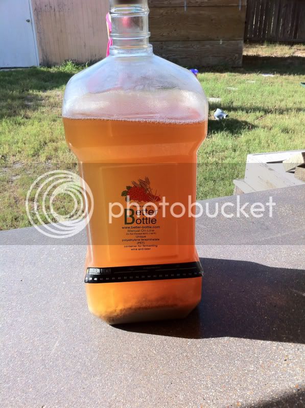
I forgot to take a pic of my plate chiller setup. It took about 10 mins to get from boiling down to 89' which is the ground water temp right now. I pumped into the better bottle and put it away in the ferm freezer to chill down.

e5d74749.jpg

d1ab0580.jpg


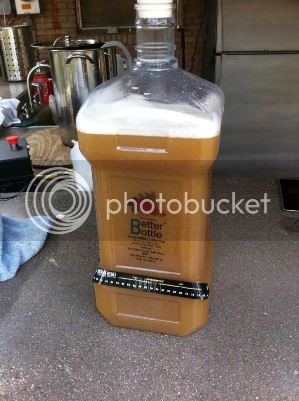
I checked it after 4 hours and I was down to 65'. Pitched half a pouch of US-05.

45ccaacd.jpg


Can't wait to brew again!

Your Build has been a great service. Thanks
Did you ever change your element connection. ? How did you handle the ground to kettle on your rubber coupling? Your build and several listed in this thread have connections without a J box but some form of rubber or PVC coupling or cap. Those that solder are the only ones I could actually see in the pictures. I would appreciate any info and hopefully pics on your method.
 
hi folks - amazing thread. i will be building my system over the coming weeks/months and will be basing the mash temp control around P-J's design.

i am currently struggling with one issue: how would i modify the original design if i wanted to keep the pump out of the PID? I plan on constantly recirculating during the mash so no need for automated control. in the current design is there an option to put the pump on manual (i.e. always on)?

Ranco 1 stage temp controller can handle 15 amps w/ internal relay. This could be used for a basic setup, no control panel required.
very useful tip, thanks. i had asked something similar about the Johnson A419 (https://www.homebrewtalk.com/f170/johnson-a419-rims-388083/) and someone mentioned that "The Johnson only cycles on and off with a 2 degree swing, even set at its narrowest offset setting." so until i get my PID box built i might use a Ranco. i can use it for fermentation control once it's been replaced by the PID.

thanks everyone!
 
...
i am currently struggling with one issue: how would i modify the original design if i wanted to keep the pump out of the PID? I plan on constantly recirculating during the mash so no need for automated control. in the current design is there an option to put the pump on manual (i.e. always on)?

...
The pump is independently controlled with its own switch. It does not and is not controlled in any way by the PID.
 
Back
Top