Bigdaddyale
Well-Known Member


I got my boards today but ran out of solder. What is JP1 used for?
So you pull the jumper and power the relays with 5v0?
That brings up a question for @Thorrak ... I see the board is marked 5v. We're good here?
I hooked up my LCD to the new board last night and it powered right up. I have not yet hooked up a relay or sensors as SWMBO was strongly encouraging me to leave my project alone for a day.
I approve of this message!Eventually I want to design a board which incorporates the relays as well, but it will blow up the BOM as well as the cost of the project (the additional PCB cost alone will be more than the relay board) and as such hasn't been prioritized.
I approve of this message!nestar:
nestar:
nestar:
nestar:
nestar:
I was going to ask about it previously, but since I'm basically putting things on a list for you to do I figured I'd keep my mouth shut.
You can put me down as a person who would definitely use the design.
If you want to go crazy, drop in high voltage as well with a power supply and you have a one-board solution.


![Craft A Brew - Safale S-04 Dry Yeast - Fermentis - English Ale Dry Yeast - For English and American Ales and Hard Apple Ciders - Ingredients for Home Brewing - Beer Making Supplies - [1 Pack]](https://m.media-amazon.com/images/I/41fVGNh6JfL._SL500_.jpg)


We should be. If memory serves correctly, the relay boards generally have an optocoupler which switches VCC to the relay. Basically it's 3.3v to the optocoupler to 5v to the relay to mains power.
Eventually I want to design a board which incorporates the relays as well, but it will blow up the BOM as well as the cost of the project (the additional PCB cost alone will be more than the relay board) and as such hasn't been prioritized.

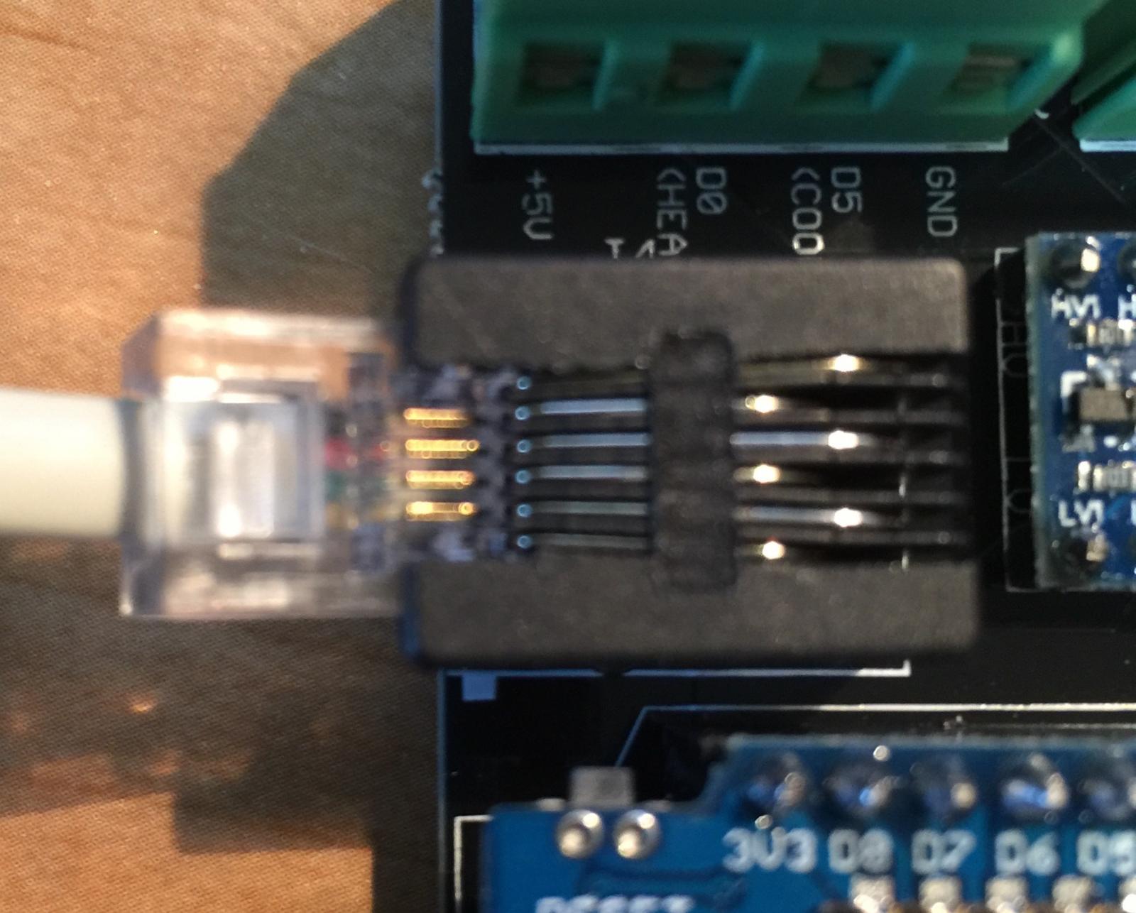
Is this right? I think you can see the colors (yes I have it pulled out slightly). I'm getting an address but no value.
I want to design a board that can be used with both SSR and relay too.
However, I don't have the knowledge. Would you shed some light on it?
I really don't understand why a few resistors and transistors will make the cost hike.
Did that ... now I get nothing.Did you reset the eeprom to its default settings? I really need to find a fix for that...
Did that ... now I get nothing.
Is that wiring order right? If so I'll re-check all my connections.
The "sainsmart" relay circuit is pretty simple, to be honest, and is readily available online. The reason I was commenting on cost is less the resistors/optocoupler/relay and more the fact that I'm guessing you would need another 2 sq. inches of space to hold it. At $4/per, that's $8/order (or $2/board). Still though. I like the thought and want to do it if I can.
Black -> VCCWhat colors did you wire the pins of the DS18B20 to?
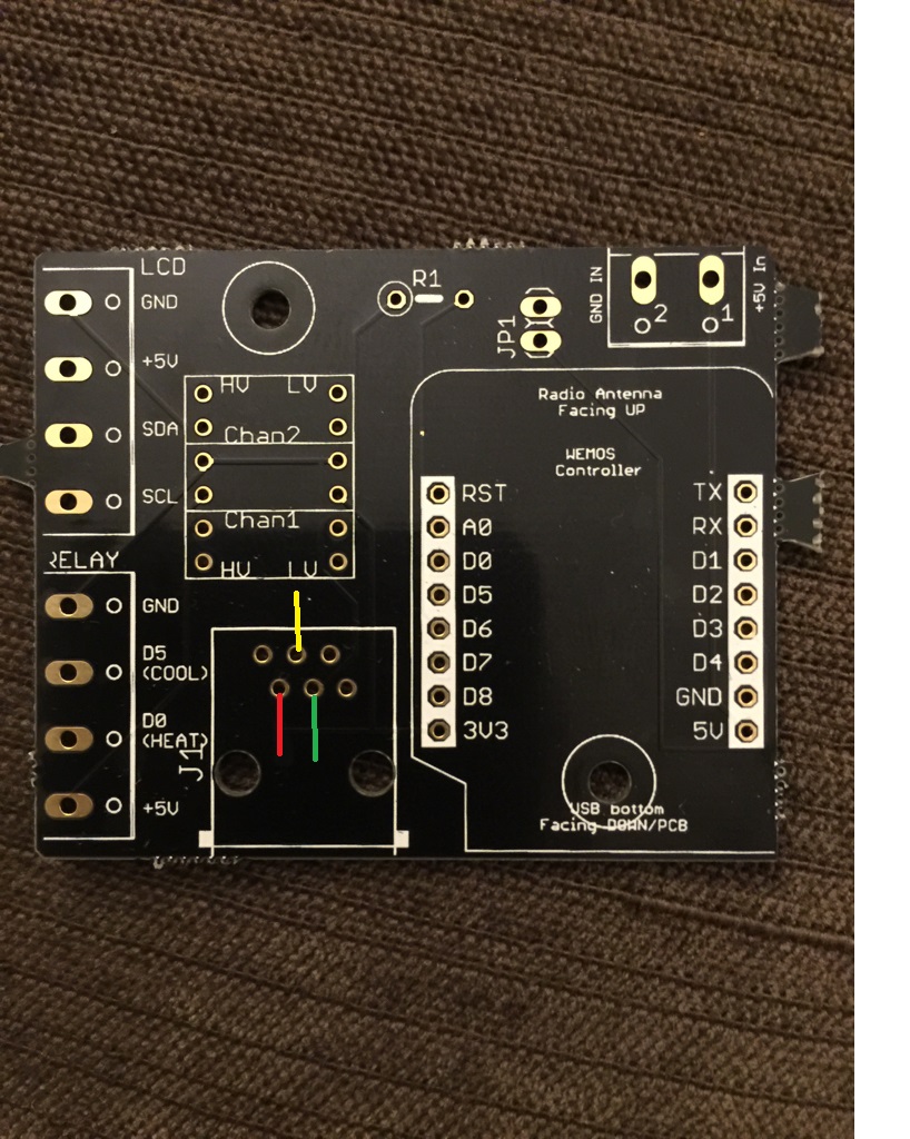
You have the through hole board not the smd board. Look at https://www.homebrewtalk.com/showpost.php?p=7722447&postcount=321 JP1 is for a buzzer and J1 is a RJ11 phone jack. R1 is for a resistorView attachment 371954ok so I've received my boards but I'm a little confused as to what goes where i.e. R1 and J1 I also thought those little Mosfets went somewhere but I can't work out where it would go.
Does any one have a step by step diagram or a layout that I can follow?
Cheers
View attachment 371954ok so I've received my boards but I'm a little confused as to what goes where i.e. R1 and J1 I also thought those little Mosfets went somewhere but I can't work out where it would go.
Does any one have a step by step diagram or a layout that I can follow?
Cheers
It looks like the DS18b20 is powered off the 3v pin of the D1 mini- is that enough power? I thought the DS18b20 needs 5vBlack -> VCC
Red -> Data
Green -> Ground
Nope, 3.0V to 5.5V. 3v3 should be fine. I've had it working before, just not on the PCB.It looks like the DS18b20 is powered off the 3v pin of the D1 mini- is that enough power? I thought the DS18b20 needs 5v
How about the 10k resistor instead of the 4.7k.Nope, 3.0V to 5.5V. 3v3 should be fine. I've had it working before, just not on the PCB.

Black -> VCC
Red -> Data
Green -> Ground
All of mine are red vcc, black gnd, yellow dataAll my sensors have Red(+), black(GND), and yellow(data) lines.
It might be right but seems weird to me by using Black for Vcc.
I usually uses RED as Vcc, Black as GND, and green as neutral.
Whys it 10k instead of the 4.7k with the temp probes? Also with the volt and ground in is this so that I could choose to power the board from a hacked up USB cable?
All my sensors have Red(+), black(GND), and yellow(data) lines.
It might be right but seems weird to me by using Black for Vcc.
I usually uses RED as Vcc, Black as GND, and green as neutral.
10k -- I don't know, actually. I think I saw something somewhere awhile back that suggested it, and so that's what I used. It works, but 4.7k also works. Use what you have.
The 5v/GND In are for you to hook up a +5V power supply inside whatever enclosure you choose to use. If you prefer to power via USB instead, you can do so also. Either work. Just don't do both simultaneously.
If you are powering via USB, however, make sure your USB power supply puts out clean power. The cheap chinese knock-off power supplies generally don't, and the ESP8266 doesn't have much in the way of filters to clean it up.
Just for fun, my sensors have green for data. You never know what you will get.All of mine are red vcc, black gnd, yellow data
Did you use v3 or 4 of the firmware? The reason I ask is when I had an address that was not the same as in the code mine did that. v4 has a small routine that finds the display automatically.Mid brewday so I can't trouble shoot the blank display but we're close View attachment 372033
Did you use v3 or 4 of the firmware? The reason I ask is when I had an address that was not the same as in the code mine did that. v4 has a small routine that finds the display automatically.
Two boards soldered up -now waiting for the resistors. I have a choice of 91% isopropyl or 70% ethyl alcohol to use as a flux cleaner which one should I use?I got my boards today but ran out of solder. What is JP1 used for?
Two boards soldered up -now waiting for the resistors. I have a choice of 91% isopropyl or 70% ethyl alcohol to use as a flux cleaner which one should I use?