Turfgrass
Well-Known Member

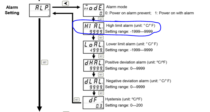
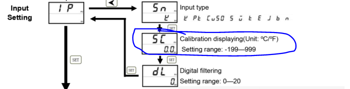
Also the alarm switch turns on the alarm immediately and I’m not sure if that is suppose to happen, or a set point must first be programmed.?? I don’t know how the pid’s work yet.
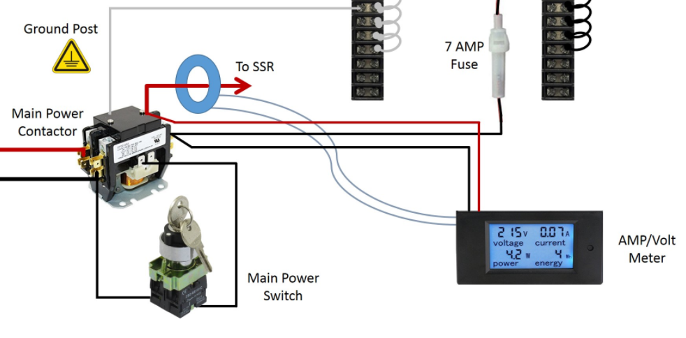
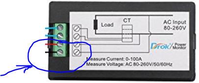
The heating element selector switch sends power to the appropriate receptacle, but I did not see if the yellow lights came on when selected and I’ll need to double check that next time around.
The wort and water pump buttons work and delivery power correctly to the receptacle.
Thank you for all of your help.
Last edited:
")


![Craft A Brew - Safale BE-256 Yeast - Fermentis - Belgian Ale Dry Yeast - For Belgian & Strong Ales - Ingredients for Home Brewing - Beer Making Supplies - [3 Pack]](https://m.media-amazon.com/images/I/51bcKEwQmWL._SL500_.jpg)