BruControl: Brewery control & automation software

Homebrew Talk - Beer, Wine, Mead, & Cider Brewing Discussion Forum

Help Support Homebrew Talk - Beer, Wine, Mead, & Cider Brewing Discussion Forum:

This site may earn a commission from merchant affiliate links, including eBay, Amazon, and others.
For future versions, have you guys thought about a having a way to clear historical data (like clearing a graph that has some garbage on it from when I was messing with the calibration math)?


One other thing that I was wondering is if there could be a way to say whether to log data for something or not? Right now, I think it remembers everything. There are lots of things I don't care about the history of, so I have no need to log that information.
Granted, storage is cheap so maybe it is a big "don't care", or a "it isn't structured that way" type of thing. Just thought I would ask.

Hmmm hadn’t thought of it. Obviously you can delete and re-create the graph, which is not ideal. As far as keeping old data, yes we were like “storage is cheap”.

We are moving all the data and logs to a database instead of discreet files. We will add some cleanup options.
 
OK, I spent a few hours... I cannot get any of my SonOff Duals to work with 1-wire and v45, the same pin works with the flowmeter in v45, and the 1-wire works if I downgrade to v43

setup - BC 1.1 build 4, SonOff dual (ESP8285) on my desk, simple 1-wire and 4.7k right to the sonoff, no cables, no other connectors , 6 inch leads... I have the interface configured and 2 temp probes and a digital output configred in BC.. the same 1-wire works on the ESP32 right next to it...


Code:
SonOff Dual downgraded to v43 and the one 1-wire shows temp 82.62

BruControl v43A.W Debug:1
Rsp:%1;
End:488644
Beg:488667
Msg:?200?201;
Rsp:?200=8262?#;
End:488668
Beg:490306


Same interface upgraded to 45(a), power cycled, and connected, Temperature does not work. The Digital output does work, but not shown here:

BruControl v45.W Debug:1
Rsp:%1;
End:42627
Beg:42945
Msg:?200?201;
Rsp:?#?#;
End:42947
Beg:44031
Msg:?200?201;
Rsp:?#?#;


and upgraded to 45C and no change:
BruControl v45C.W Debug:1
Rsp:%1;
End:22168
Beg:22958
Msg:?200?201;
Rsp:?#?#;
End:22960
Beg:23983
Msg:?200?201;
Rsp:?#?#;


I then completely removed the interface from BC(which removed the devices) and re-installed as a differrent named interface with newly named devices on same ports, still no temps:

BruControl v45C.W Debug:1
Rsp:%1;
End:43066
Beg:43302
Msg:?200?201;
Rsp:?#?#;
End:43304
Beg:44329
Msg:?200?201;
Rsp:?#?#;


Then as a last ditch, I re-downgraded back to v43 and BAM... the temp works again:
BruControl v43A.W Debug:1
Rsp:%1;
End:65358
Beg:66017
Msg:?200?201;
Rsp:?200=8217?#;
End:66018
Beg:67096
Msg:?200?201;
Rsp:?200=8217?#;

I’m embarrassed to say this because I should have realized you said Sonoff before... realizing the current FW won’t address the Sonoff’s 1-wire correctly. We’ll fix it and get a new version up. Sorry for wasting your time on it.
 
I’m embarrassed to say this because I should have realized you said Sonoff before... realizing the current FW won’t address the Sonoff’s 1-wire correctly. We’ll fix it and get a new version up. Sorry for wasting your time on it.

Make the 8285 based sonoffs OTA and all is forgiven ;-) and go have a beer....
 
Can we use one of these Load Cells? I am thinking this would be a great way to measure mash and sparge volume.
https://www.amazon.com/gp/product/B07H3MH953/ref=ppx_yo_dt_b_asin_title_o03_s02?ie=UTF8&psc=1

I would assume you would need something like this to talk to the Mega:

https://www.amazon.com/SparkFun-Loa...7WD648XJ29P&psc=1&refRID=72JHM3Z9F7WD648XJ29P

there is a discussion 10-20 pages back about this and how you can get it working... search this thread for the HX part you mention. it is a bit convoluted, you need to convert it to analog, and then use an analog input... and there is some discussion about how many bits are useful. direct to SPI does not work at this time...


Now, while we are talking about it, I would like to use the scale that has a serial port and can put out a data point every second such as
Code:
     0.2 kgN T
     0.2 kgN T

or
Code:
    44.2 kgG
    44.2 kgG
    58.0 kgGM
   117.2 kgGM
   133.0 kgGM

or
Code:
    44.2 kgG
    44.2 kgG
    58.0 kgGM
   117.2 kgGM
   133.0 kgGM
 
Can we use one of these Load Cells? I am thinking this would be a great way to measure mash and sparge volume.
https://www.amazon.com/gp/product/B07H3MH953/ref=ppx_yo_dt_b_asin_title_o03_s02?ie=UTF8&psc=1

I would assume you would need something like this to talk to the Mega:

https://www.amazon.com/SparkFun-Loa...7WD648XJ29P&psc=1&refRID=72JHM3Z9F7WD648XJ29P

Here is a guy using the HX711 with SPI, not I2C... I know that brundog said that I2C was on the roadmap, but if this things works with SPI, that would be awesome...

What I do see from places like sparkfun is that they are using special code on discrete pins for the HX device... not I2C or SPI.. which is not the greatest for BruControl when compared to using standard SPI...

I think that weight/mass is a great thing to ask for, and it seems that if we can get it to be something that you wire and configure just like an RTD, that would be the easiest.

I bought an ADS1118 that is 16bit and SPI, which on paper seems awesome, but have not played around with it yet..
 
Be nice if the libraries were included for the sparkfun amp with the code written for Output to BruControl. Since paledragon has the code, maybe incorporate on the esp32 as I am only using it for the Tilts.
 
Just successfully put BruControl firmware onto a Sonoff TH10. Thanks to @smort for pointing this option out! I will be posting up a video how to build one of these soon!

Thinking a Sonoff Dual (http://a.co/5CGyL1w) with 1-wire probe and power cord for around $35 DIY would make for a really easy fermentation controller, controlled by BruControl over Wi-Fi. Also thinking a Sonoff 16A (http://a.co/i9UUNfR) for the same cost would make for a quick BIAB or basic RIMS controller.

Edit: Was too excited... added a quick demo video:


I fiddled with a brand new TH10 today... had not worked with them until now. Mine are version 2.1 and the chip is a ESP8266EX. I could program firmware v43 and v45, but could not get network setup to start on either firmware. After a bunch of googling, it seems the thing draws more power than the USB-Serial adapter can provide... I tried doing the network setup with the Vcc lead disconnected and the unit powered. That let v45 configure the network and I was up an running... reprogramming with v43(flash looked successful) left it dead in the water, re-flashing to v45 and it connected again.

As far as usefulness, I can turn on the Relay/Red LED, and I can turn on the blue LED.. I set up other things on every IO available and that is about all I can get working... I am comparing the two interface maps and seeing what else I can do with the 4-pin mini-jack... I am hoping that new firmware that gets v45 working with 1-wire will allow the TH10 1-wire to work, and a pie-in-the-sky dream is to have the "Sonoff TH Sensor Si7021" combo temp and Humidity Sensor that they sell for $4.30 work fully. (The humidity is also 1-wire, the 4-conductor jack looks to only actually use 3 wires.) I am happy to donate a TH10/sensor if that will help get the ball rolling..
 
Last edited:
I tried searching all afternoon, is there a way to evaluate if a script is running (evaluate from inside of another script)?

Code:
if "Script 1" State == true
 print "Script 1 Running"
endif

I eventually want to use it to have the bootloader script only allow one 'process script' to run at a time.. so I can eliminate the 6 different configurations I have, I am setting a digital output on when the bootloader starts a process script, and shutting it off before the process script exits, but if the script exits, the bootloader script still thinks it is running...
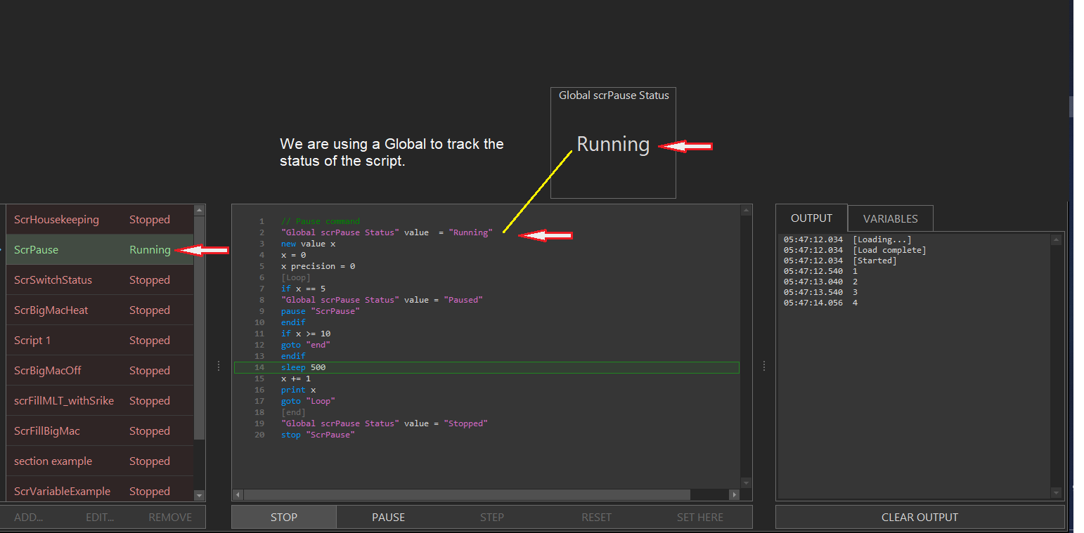
You could just add a global and update it when you do something to a script. You could set the initial value as "Stopped" and then always have "Running" as Line 1. Every time you do something tio the script, change the global.
pause condition to resume.png
 
Not understanding how that script is implemented.. it looks like it just counts to 5 and pauses...

I need to cover the case of the script stopping via the 'stop script' button, or an error anywhere... I have a toggle now, but it is not good enough
 
Something in this block of code is wrong, and I get an unmatched "end" in my script. If I comment out the "[underlet_flow_loop]" I don't get the unmatched end problem. It isn't clear to me why this would be a problem.

Code:
if "Xfer to MT" State == True
     "Xfer to MT" State = False  //reset button state
     "RST BK Flow" State = True //reset the flow meter to set count to zero
    //do some flow control to get 8 minutes transfer time
  [underlet_flow_loop]
  if BK_Flow Rate < 30
      BK_PropVA Value += 2
  else
      if BK_Flow Rate > 40
          BK_PropVA Value -= 2
      endif
  endif
  //if all of the strike water is transferred then stop, otherwise keep looping the flow control
  if BK_Flow Total < Strike_Liters Value
    sleep 3000
    goto "underlet_flow_loop"
  else
    BK_PropVA Value = 0
    BK_Pump State = False
    sleep 2000
  endif
endif

Editing the code to be this instead, I don't get a problem. Note that this is all running in a big parent loop that keeps the thing iterating instead of just going around the 'underlet_flow_loop' doing it.

Code:
if "Xfer to MT" State == True
     "RST BK Flow" State = True //reset the flow meter to set count to zero
    //do some flow control to get 8 minutes transfer time
  if BK_Flow Total < Strike_Liters Value
    sleep 3000
    call "underlet_flow_loop"
  else
    BK_PropVA Value = 0
    BK_Pump State = False
    sleep 2000
    "Xfer to MT" State = False  //reset button state
  endif
endif

//subroutine
[underlet_flow_loop]
  if BK_Flow Rate < 30
      BK_PropVA Value += 2
  else
      if BK_Flow Rate > 40
          BK_PropVA Value -= 2
      endif
  endif
return
 
Last edited:
Not understanding how that script is implemented.. it looks like it just counts to 5 and pauses...

I need to cover the case of the script stopping via the 'stop script' button, or an error anywhere... I have a toggle now, but it is not good enough

I think we can add a cross-check to see if a script is running.
 
Something in this block of code is wrong, and I get an unmatched "end" in my script. If I comment out the "[underlet_flow_loop]" I don't get the unmatched end problem. It isn't clear to me why this would be a problem.

Code:
if "Xfer to MT" State == True
     "Xfer to MT" State = False  //reset button state
     "RST BK Flow" State = True //reset the flow meter to set count to zero
    //do some flow control to get 8 minutes transfer time
  [underlet_flow_loop]
  if BK_Flow Rate < 30
      BK_PropVA Value += 2
  else
      if BK_Flow Rate > 40
          BK_PropVA Value -= 2
      endif
  endif
  //if all of the strike water is transferred then stop, otherwise keep looping the flow control
  if BK_Flow Total < Strike_Liters Value
    sleep 3000
    goto "underlet_flow_loop"
  else
    BK_PropVA Value = 0
    BK_Pump State = False
    sleep 2000
  endif
endif

Editing the code to be this instead, I don't get a problem. Note that this is all running in a big parent loop that keeps the thing iterating instead of just going around the 'underlet_flow_loop' doing it.

Code:
if "Xfer to MT" State == True
     "RST BK Flow" State = True //reset the flow meter to set count to zero
    //do some flow control to get 8 minutes transfer time
  if BK_Flow Total < Strike_Liters Value
    sleep 3000
    call "underlet_flow_loop"
  else
    BK_PropVA Value = 0
    BK_Pump State = False
    sleep 2000
    "Xfer to MT" State = False  //reset button state
  endif
endif

//subroutine
[underlet_flow_loop]
  if BK_Flow Rate < 30
      BK_PropVA Value += 2
  else
      if BK_Flow Rate > 40
          BK_PropVA Value -= 2
      endif
  endif
return

You cannot have a section heading split an if/endif block - that is why.
 
Can you only have one esp32 connected at a time via wifi . I got one with an external antenna and it has the same ip as my other one. They are both connected now with the same ip address. I do not intend to have two, just curious.
 
You can't use the same IP address across multiple devices on the same network. Need to either statically assign unique ones (per @clearwaterbrewer) or use DHCP and let the router assign unique ones (danger here is your router could change a particular device's IP from assignment to assignment, which will break BC <-> interface communications).
 
I figured that. I did have one as static and then had the other as DHCP to get an IP Address. I just thought is was odd that it was the same address. Maybe the MACs are the same on ESP32 boards. BTW, the one with the antenna read the Tilt from about 50 feet between two walls (one with foil covered foam board and a steel door) inside a single walled Stainless conical.
 
I like to assign dhcp reservations from router on devices. That way your device gets a static ip address (required for brucontrol comms), but the list is centrally controlled on your router.

Agreed. To me it's just easier to access my AmpliFi app and change reservations. Way faster than accessing individual devices and messing with different OSes.
 
I figured that. I did have one as static and then had the other as DHCP to get an IP Address. I just thought is was odd that it was the same address. Maybe the MACs are the same on ESP32 boards. BTW, the one with the antenna read the Tilt from about 50 feet between two walls (one with foil covered foam board and a steel door) inside a single walled Stainless conical.

MAC addresses are "technically" hard-coded and cannot be duplicated (though MAC's can be coded in software). Anyway, your DHCP server will not necessarily know another device out on the network has the same IP which was self-assigned statically. The DHCP server issues IP's based on a "pool" of available ones. This is the danger of mixing static and dynamic IP's - you need to make sure your static IP's are not in the range of the DHCP pool. I suggest you write it all down in one place.
 
MAC addresses are "technically" hard-coded and cannot be duplicated (though MAC's can be coded in software). Anyway, your DHCP server will not necessarily know another device out on the network has the same IP which was self-assigned statically. The DHCP server issues IP's based on a "pool" of available ones. This is the danger of mixing static and dynamic IP's - you need to make sure your static IP's are not in the range of the DHCP pool. I suggest you write it all down in one place.

If DHCP is implemented properly, it will not give out a duplicate, due to other devices on the wire seeing the DHCPoffer packet and complaining, but if an address that was given out happens to be one of a statically defined device that is powered up after the DHCP is given, it will cause an error... This is why there are things such as dhcp pools / dhcp excluded addresses... Your statics should NEVER be in the range of the DHCP scope for this reason... people do it, it works, until it doesn't... I suggest using 100% DHCP static reservations(other than the router/DHCP server) ,or at least use them for x.x.x.2-99 and then use DHCP for x.x.x.100-199, and then true statics for x.x.x.200-253
 
Most routers allow specifying an IP address range for the DHCP service. I have a 50 address slice of my LAN space set aside for guests, and everything else in the house from computers through AV equipment and TVs through tablets and cell phones and cameras are either on static addresses or DHCP reserved addresses...

Cheers!
 
Got my interface in the other day and have connectivity to computer. Cant for the life of me get one of RTD (PT100) to show in BC via SPI Sensor. Ive ensured the following...

1. 5v across VCC and GND at RP-3- This is currently pulled from interface (Mega)
2. D52 to CLK
3. D51 to SDI
4. D50 to SDO
5. Soldered jumpers and cut trace per 3 wire Adafruit 31865 instructions, checked continuity and passed
6. D14 to CS1- Also tried to CS2, 3 and 4 with respective chips (I have 4 of them)
7. Ensured D14 pin used and port 14 with SPI device
8. Ensured RTD calibration at 430 with C to F conversions downstream
9. Wired RTD per Adafruit 31865 instructions, even tried all combinations
10. Swapped out RTD to ensure this wasn't the problem.

What am i missing? I am currently using USB to power interface.. I don't need 12v wired in for this correct?
 
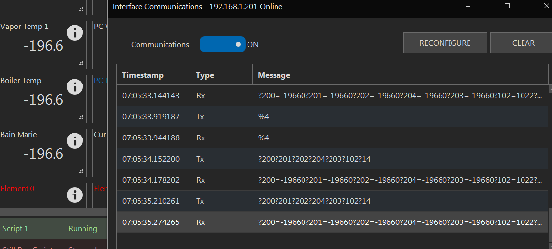
does %4 work from the interface communication screen? what does it do? I can't seem to get it to change anything...
both entries with a -196.6 and with --- are not changed...

View attachment 645567

View attachment 645568

The reset is taking place since the interface responded to the %4 command. -196 is a 1-wire error. Something is not right on the bus. On the second screen, the #'s indicate an invalid port. This means you reset the bus but the ports were not then re-established. Hit the "Reconfigure" button, and these will then get established and should start reporting.
 
Got my interface in the other day and have connectivity to computer. Cant for the life of me get one of RTD (PT100) to show in BC via SPI Sensor. Ive ensured the following...

1. 5v across VCC and GND at RP-3- This is currently pulled from interface (Mega)
2. D52 to CLK
3. D51 to SDI
4. D50 to SDO
5. Soldered jumpers and cut trace per 3 wire Adafruit 31865 instructions, checked continuity and passed
6. D14 to CS1- Also tried to CS2, 3 and 4 with respective chips (I have 4 of them)
7. Ensured D14 pin used and port 14 with SPI device
8. Ensured RTD calibration at 430 with C to F conversions downstream
9. Wired RTD per Adafruit 31865 instructions, even tried all combinations
10. Swapped out RTD to ensure this wasn't the problem.

What am i missing? I am currently using USB to power interface.. I don't need 12v wired in for this correct?
One or all?
 
The reset is taking place since the interface responded to the %4 command. -196 is a 1-wire error. Something is not right on the bus. On the second screen, the #'s indicate an invalid port. This means you reset the bus but the ports were not then re-established. Hit the "Reconfigure" button, and these will then get established and should start reporting.

Forgive me, what is the "Reconfigure" button? I even searched the manual for the word 'reconfigure' and it does not appear. Is this for the interface or the element?

FYI - The '----' are on the v43 sonoff dual and the '-196.6' are on a Mega... neither can be cleared by disconnecting all the probes, wiggling the cable, etc... both can be cleared by a power cycle of the interface. the mega takes a good 10 second power-cycle, a 2 second one does not always do it.

EDIT: I found it: Interfaces --> Communications --> Reconfigure
I tried it several times and it does not change anything. (I know a power cycle will in fact fix it, but am waiting to see if I can diagnose...)
 
We should take this offline to avoid cluttering this thread... the first screen shows you did 'RECONFIGURE' (this re-establishes all the devices/ports to make sure they are as expected following any manual changes or resets. In that case, the response included hash signs, which means in this specific case, that 1-wire sensor index was not found on the bus. This leads me to believe there is some type of hardware problem with the 1-wire bus.

Similar with the second screen... the sensors were found but they are reporting incorrectly... likely also noise or some hardware problem.

It's best to try to troubleshoot 1-wire sensors one at a time. Try disabling them all then re-enabling them one at a time, and if that doesn't work, physically connect just one at a time.
 
I will take this offline, save for one question:

Can BC truly add or remove and reinstall a 1-wire sensor from an interface without powering off the interface, by any manner of disconnecting/reconnecting, disabling/enabling, pressing the 'Reconfigure' button, sending '%4', or any other means that is NOT powering off the interface? If not, this feature is desperately needed.
 
Last edited:
Yes, %4 initializes the bus the same way it does during interface power-on. The device-port assignments will not work if the bus devices change at all until the 'RECONFIGURE' button is pressed, or the devices are disabled and enabled.
 
Start with one only. Get that to work before expanding to more. Use a meter to make sure the voltages are correct and connections are correct and working. Disconnect all other devices to isolate just the one amplifier. If you want to email us pictures, that could help.
Perhaps I misunderstood your question. I am only trying for one amplifier to work, not all. When i get my head wrapped around one and its wodoing, ill hook the rest up. All other devices are not yet hooked up. Just the interface and amplifier board
 
feature request:

Would be nice to have a command to reset the reset value of a timer. In other words

"timer1" resetvalue = 00:1:15
restart "timer1"

and then later

"timer1" resetvalue = 00:4:35
restart "timer1"

I have different vessels that require different times to fill and depending on what I am doing, even the same timer for the same vessel may be different. Would be easy with Count Up as it always starts at 00:00:00 , but not count down using a global as the end time.


I like count down to let me know how much time is left.
 
Not sure I'm following on the reset... if you know the times, assuming you are using a script, just issue a "timer1" value = "00:04:35" after a wait command looking for the 1:15 timer to hit 00:00:00.

You don't need to stop the timer to give it a new time.
 
Not sure I'm following on the reset... if you know the times, assuming you are using a script, just issue a "timer1" value = "00:04:35" after a wait command looking for the 1:15 timer to hit 00:00:00.

You don't need to stop the timer to give it a new time.
I will try that. I did not think of setting the value of the timer like that. It is sort of the same thing. If the command was there it should be "set" to be consistent with the element.
 

Latest posts

Back
Top