HOWTO - Make a BrewPi Fermentation Controller For Cheap

Homebrew Talk - Beer, Wine, Mead, & Cider Brewing Discussion Forum

Help Support Homebrew Talk - Beer, Wine, Mead, & Cider Brewing Discussion Forum:

This site may earn a commission from merchant affiliate links, including eBay, Amazon, and others.
Status
Not open for further replies.
Mine are stereo plugs generally I just leave them in. I I did it again I'd prob use telephone jacks and flat cable. The flat cable would sit across the door seal better.


Sent from my iPhone using Home Brew
 
You could use a CAT5-6 cable as well, but it is generally a thicker cable and didn't fit as easily into my probe end, But would definitely work. You have to be wary of the telephone cable because they are a cross-over style cable and close attention needs to be paid to which conductor is being used when soldering up the sensor.

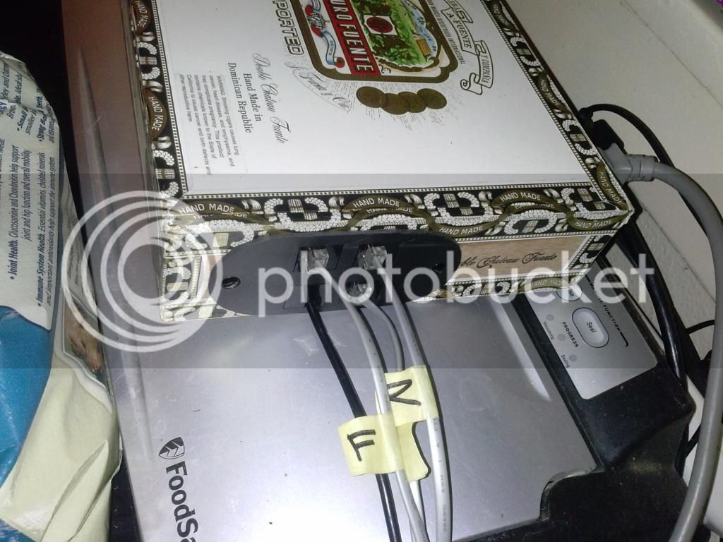
Here is a picture of my connections using the flat telephone cable.

2014-10-24233938_zps9fc2e15f.jpg
 
Hmm.. I broke it, need help from you linux whizzes... (This is wheezy running on a laptop.)

Everything was working fine, and actually still is, other than plotting the results. I stopped the "brew" I had running name "test". And went to create a new one. Entered a name for it when asked and clicked the Start New Brew button. It throws an error "Could not receive reply from the script."

The Python script is running fine. I restarted it to be sure. Brewpi is running fine, the Arduino and relays are responding to mode changes, etc., everything else seems normal, LCD panel shows all the right stuff. Just can't log my brew to the graph.

Some permission problem with the json data file?


STERR shows:

Nov 11 2014 16:52:48 Stopped data logging, as requested in web interface. BrewPi will continue to control temperatures, but will not log any data.

Nov 11 2014 16:56:22 Socket error(32): Broken pipe
Traceback (most recent call last):
File "/home/brewpi/brewpi.py", line 567, in
conn.send(json.dumps(result))
error: [Errno 32] Broken pipe


code block at line 567:

elif messageType == "startNewBrew": # new beer name
newName = value
result = startNewBrew(newName)
conn.send(json.dumps(result))
 
I did stop the old brew first (which was graphing fine when I stopped it). There's no brew now. The error comes when I try to start a new one.
 
Read back on this thread a few pages. It was discussed here earlier.
 
Thanks to all that have gone through this before me. I am starting my build and have a couple questions. Skip to the end if this is too long and you don't want to read about the overall plan.

Now, I haven't read all the posts here but I have read quite a bit of them and it make sense. From what I have figured out I am going to need two Arduino boards. I picked up a Beverage Air DD94 Keggerator (not this one but one just like it) at a local auction. Scored it for $75

SD-BEVA-DD94-1-B-2-2.jpg


The thermostat is dead in it but that is an easy fix with BrewPi. It doesn't have the towers on it so I will be building a tower out of wood so I can have taps on one side and BrewPi on the other. The tower will be like one of those in many bars that has two posts with a "bridge" spanning the two posts so I have room for the taps and everything. I plan on splitting the cooler in half with one side for serving beer/cold crashing and the other for fermenting. This is why I have come to the conclusion that with the current build of BrewPi I will need two Arduino boards. One will replace the built in defective thermostat for the cold side. The other will control fans/heat to control the fermentation side. That is the plan anyhow. I picked up a RaspberryPi to do the web stuff and have that all ready to go. Linux installed on it and hooked up the first Uno board last night to flash it. At this point I can log in and everything looks good. No data yet as the temp probes are not connection. A few days ago I wired up the circuit with a 4 relay board and the optional LCD on a breadboard but still need to make the final connections to the Uno. I figured it was best to flash it with nothing connected as I had been playing around with some the labs out there on the Uno. It wasn't much more for the 4 relay vs 2 and may be nice if they release the new version where one Arduino can do everything. It seems like I wasn't the only one out there running the 4 relay board for this reason. The LCD display(s), while not needed, are being used because I think they would look cool in the tower. Since I am building the controllers first, I can plan out the LCD stuff now on the bench and then build the tower to accommodate.

So on to my questions.

1. I ordered 4 of the temp probes from Amazon as I was thinking 2 per Uno. They came from China. I figured that they were made there but didn't think they were mailed from there so it took about a month to get them. For running this I have seen people using 2 probes others using 3. I get were people measure air temp in the fridge/chamber and beer temp. What is the 3rd used for? Should I order more probes before I get much further? If I need more I want to get them ordered as it will likely be Dec before I see them.

2. Anyone using their RaspberryPi for other things at the same time as BrewPi? I am building a BCS460 based electric brewery at the same time. I need a computer to log into the web interface. I was thinking I could mount a LCD TV (Black Friday around the corner) behind the keggerator/ferm chamber, mount a HDMI output jack on the back of the tower and stand there to log into the BCS 460 for brewing. I am only really in need of a web browser so not talking a huge load. Besides the Arduino board(s) are doing all the work. Worst case, I might loose some logging if it can't keep up as I assume it is stored on the Pi. I did get the newer RaspberryPi which is a little better than the originals. This is my first time using them though. So still figuring them out. If it is an issue, I will just order another one for this. I am kind of thinking about getting another one anyhow as I think it would be cool to have XBMC running on it out in my shop. I can see where that would push it too hard.
 
Has anyone run into issues powering the Arduino over USB?

USB power has a nominal voltage of 5V, and so does the RaspberryPi B+. According to the Arduino documentation, the lower limit input voltage is 6V.

Obviously for this project nothing on the Arduino is very power intensive, but I am curious if there are any known problems.

Several people have had several issues. Better/different USB cables solved some issues; routing USB away from power solved some; powering Arduino separately from re-purposed cell phone wall wart 5V USB solved some. Lots of posts in this very thread about it all.

....aaaaaaaaaaand DayTrippr has a *MUCH* better answer.
 
There have been lots of issues powering Unos from 'Pi boards.

What I found - and note the next reply as well. There have been plenty of others if you go back through this thread, where folks were trying all kinds of different cables to solve what was thought to be an SI issue.

And what I did about it...

Cheers!

[edit] A quickie look at the schematics for the Model B RPi and the R3 Sainsmart Uno reveals no clue about the voltage drop I observed when powering the latter from the former's root port. The only polyfuse in the entire path from the Model B RPi microusb input power connector to the Arduino atop the Uno is back at the RPi between that microusb receptacle and the rest of the board, and I don't see an appreciable drop across it.

I'll be able to look at this closer when I put my dev system back together, but my guess at this point is there isn't enough copper end to end to support the Uno's power requirement. Might be on either board (though I'd suspect the RPi first).

As for the B+, I've only ever been able to find a single schematic page, and it doesn't exactly show how the USB root ports get their power (in fact none of the four root port receptacles appear on the page). It does show the microusb input power receptacle with a 2A polyfuse then a [edit:] FET that prevents the RPi back-powering that power receptacle [not a diode - so the drop is likely inconsequential]. I expect the root ports are powered by the FET output directly.
 
Several people have had several issues. Better/different USB cables solved some issues; routing USB away from power solved some; powering Arduino separately from re-purposed cell phone wall wart 5V USB solved some. Lots of posts in this very thread about it all.

....aaaaaaaaaaand DayTrippr has a *MUCH* better answer.

There have been lots of issues powering Unos from 'Pi boards.

What I found - and note the next reply as well. There have been plenty of others if you go back through this thread, where folks were trying all kinds of different cables to solve what was thought to be an SI issue.

And what I did about it...

Cheers!

Thanks guys, I had a feeling it might cause issues. I will go read through some of this. Appreciate the help!
 
USB power has a nominal voltage of 5V, and so does the RaspberryPi B+. According to the Arduino documentation, the lower limit input voltage is 6V.

I think the documentation is referring to the fact that the power jack on the Arduino needs extra volts because it has a regulator which drops a couple volts. So I'd use minimum 7.5 Vdc on the power jack, but I don't think the USB power has/needs a regulator on the Arduino so 5V is fine coming from that direction.


..Todd
 
I powered my arduino off the pi for the first half dozen batches I fermented with it without an issue and without a display. Once I added the display things started getting a little dicey, the display was dimming because the 5V supply was dropping into the 3.5v range. I plugged it into it's own wall wort and the future is much brighter!
 
Alrighty gentlemen, riddle me this:

Could I bring in one wall wart at 12VDC and split it off into two branches? One powers my Arduino directly, then another feeds an LM78xx circuit to output 5VDC, then the RaspberryPi is powered from that.
 
As for the B+, I've only ever been able to find a single schematic page, and it doesn't exactly show how the USB root ports get their power (in fact none of the four root port receptacles appear on the page). It does show the microusb input power receptacle with a 2A polyfuse then a [edit:] FET that prevents the RPi back-powering that power receptacle [not a diode - so the drop is likely inconsequential]. I expect the root ports are powered by the FET output directly.

It's been my understanding that the raspberry pi b 5v is simply the unregulated supply voltage, the 5v on the GPIO header and the USB ports run off what ever you are supplying. I could be wrong.
 
It's been my understanding that the raspberry pi b 5v is simply the unregulated supply voltage, the 5v on the GPIO header and the USB ports run off what ever you are supplying. I could be wrong.

I already covered that, based on the Model B schematics.
Aaaand I'm pretty sure I covered what applies to the Model B+ as well...

Cheers!
 
Alrighty gentlemen, riddle me this:

Could I bring in one wall wart at 12VDC and split it off into two branches? One powers my Arduino directly, then another feeds an LM78xx circuit to output 5VDC, then the RaspberryPi is powered from that.

That would be a rather inefficient way to do it, but it would work.

That LM7805 will likely run quite warm and a heat sink will certainly be required. As well, if you're using the typical Sainsmart Uno R3, the linear regulator on that will run hot, too.

If you don't already have that 12VDC wall wart, I'd recommend using a 7.5VDC wart instead. There'd be a lot less heat generated. Or even better, do the Uno mod I did, and run both boards from a 5VDC source...

Cheers!

I have an actual Arduino Uno. Not sure on the Rev, but a true blue Arduino. I don't know if that makes a difference on the reg, but I have been running it on a 12V wall wart for a year without issue. It was my fermentation controller before and I'm re-purposing it.

I actually have the 12V wall wart already and all of the parts to do a LM7805 circuit. I have a heatsink, so if efficiency is my only enemy then I think that's the way I'll go.
 
Which part is the regulator on the Sainsmart UNO R3? I'm a bit (okay a lot) out of the loop on surface mount parts and numbers -- I didn't see any TO-3 series pass devices, Lol. I'm using 9 VDC and I'd like to monitor how hot it's getting.

..Todd
 
Hmm, I might have to look into a wall wart as well. If I am running 2 Unos with displays I'll bet the single RPi B+ won't be able to keep up. Being I work in IT I have easy access to old ATX desktop power supplies. What about getting 5V from one of those? I need to power some 12V fans and I was thinking I could run everything off a PC power supply. In my case I want a couple 12V fans for a blower to pull cold air over to the warm side controlled by the relay on the BrewPi. Then some to keep the air moving in the fermentation chamber and fridge on the keggerator side. Any reason I can't power a pair of Unos and the RaspberryPi from that as well?
 
If you are concerned about power issues you could power the arduinos and the pi from a USB hub. Another power leech in the mix can be the relay board. You can remove the power jumper from the relay board and power it independently from the arduinos.
 
I'm thinking of extending the Sainsmart relay board active state LEDs out to the box since my box is not transparent. Is there any current draw concerns if I just connect an LED and its limiting resistor to the Arduino ports for those pins? (or the same connection at the relay board end?)

The relay board draws 15-20 mA per channel apparently, and the LED would need another 10-ish. Not sure what the danger zone is for the Arduino pins.

EDIT: My buddy Google tells me 20mA is the recommended I/O port max and 40 mA is the absolute max on a real Arduino. That leaves me teetering a bit close to the edge. Maybe I should instead remove the SMD LED from the relay board and extend it out to the chassis.

Hmm... another idea.. fiber optic filament from the SMD LED out to the box.

..Todd
 
Which part is the regulator on the Sainsmart UNO R3? I'm a bit (okay a lot) out of the loop on surface mount parts and numbers -- I didn't see any TO-3 series pass devices, Lol. I'm using 9 VDC and I'd like to monitor how hot it's getting.

..Todd

It's the DPAK with the big thermal pad immediately to the side of the barrel receptacle. An MC33269ST-5.0T3 fixed linear regulator. If you look closely you can see there's a big slab of top side copper just under the solder mask that the thermal pad uses to sink heat.

fwiw, for a 5VDC output the optimal voltage input to this device is actually around 6.2 VDC, it can achieve it's full rated output power with that input voltage. Anything above that just makes more heat.

Of course you can't find a 6.2 VDC wall wart, the closest "standard" is 7.5VDC. But I ran one of my Sainsmart R3 Uno boards with a 9VDC wart for awhile and had no problem. Never ran it with a 12VDC source though...

Cheers!
 
So I got my dev system up and running again. I put back the switching FET on the UNO (that I had removed to allow direct 5V power) to do some voltage drop testing while powering the UNO from an RPi Model B via the USB connection. I set it up with the complement of components and connections commensurate with a single-instance BrewPi configuration plus a RaspberryPints V2.01 tap manager, my PIR motion sensor and five channel temperature logger.

After going end to end from my 5V power supply through the RPi out to the UNO board to the AVR chip, it appears the biggest potential for voltage drop is from the USB cable. Depending on which of three different 18" USB cables the drop across the cable ranged from under 60 millivolts to over 250 millivolts.

Meanwhile, the end-to-end drop on the RPi from its micro-USB power receptacle to its USB root port connectors was only 70 millivolts, nearly all of that due to the polyfuse. And the drop at the UNO from its USB receptacle to the AVR was only 20 millivolts, again mostly incurred by its fuse.

Add it all up and with a solid 5.02 volts at the input to the RPi, with the best cable the voltage at the AVR was 4.87 volts, and with the worst cable it was 4.62 volts. The latter is still within the 10% component level tolerance typical of commercial components of modest technology, but it's well outside of the 5% that most module designers specify.

Bottom line: it makes sense to me that folks were seeing varying results with different cables. And, fwiw, my best cable was also the fattest...

Cheers!
 
ImageUploadedByHome Brew1415859750.101359.jpg
Been using these cheap ebay dc to dc buck converters to dial down the reqd voltage if using a power supply that is rated too high. You can dial up 5v at the end of the cable. Pi's have problems with some power supply's that say 5v but actually put out 4.5 because of poor cables. You can then use a wider range of walwarts.


Sent from my iPhone using Home Brew
 
It's the DPAK with the big thermal pad immediately to the side of the barrel receptacle. An MC33269ST-5.0T3 fixed linear regulator.

Thanks.

Of course you can't find a 6.2 VDC wall wart, the closest "standard" is 7.5VDC. But I ran one of my Sainsmart R3 Uno boards with a 9VDC wart for awhile and had no problem. Never ran it with a 12VDC source though...
Cheers!

Real Arduinos are rated to 12v at the power socket, which tells me there is some confidence that they can reliably dissipate the extra heat. I don't trust Sainsmart products to deliver against those same specs but I think 9V is probably reasonable, as a guess.

I thought my pilfered wall wart circuit was 7.5v but it measures over 10v unloaded. The case and label are long gone. I didn't bother measuring it in situ, I just assume it's 9v and dreamt it was 7.5.

Your power tracing results are great info. Thanks for doing that.

..todd
 
Thank you guys for all your help yesterday!

Last night I soldered up my system power supply. I have 12VDC coming in to the box. From there, a 12V line goes to my Arduino, and another 12V line goes to a small case fan I put in the box. This will draw heat out from the LM7805 heat sink and whatever heat the Arduino and RPi put off. I then have a 7805 circuit that puts out a steady 5.2V.

Plugged it in, tested the outputs, and connected everything up. Arduino and RPi turned on ran just fine. I guess the true test will come once everything is put together and the system is running, but for now I'm satisfied.

I used this link as the backbone for regulator. I used slightly different values for my capacitors and resistors, but to the same effect. If anyone would like them (or any pictures) I can share tonight.

Cheers!

Pictures please. :ban:
 
Now that I've added a LCD display to my Brewpi, I was wondering about adding a selector encoder. Has anyone done it? Is it worth the effort?

Hmm... I ordered the knob and encoder, I'll report out what I find when I install it.
 
I still cannot see the need to do so when the software allows you to change the inverted state

Yes the software allows you to change it but then you have to use the Normally Open side of the relays and the LEDs would stay on when they "should" be off. I don't like that. The reason I was having the issue at all versus most of you guys is that I was using the shield. I finally figured that out and now mine works just like it would without the shield but I also have the LCD and Rotary.
 
I'm no electronics engineer but it looks to me like you followed the "basic idea" schematic, I got the impression that was just the starting point to a good PSU for the pi. Can anyone else speak to the suitability of this PSU?
 
I'm no electronics engineer but it looks to me like you followed the "basic idea" schematic, I got the impression that was just the starting point to a good PSU for the pi. Can anyone else speak to the suitability of this PSU?


You're absolutely right, this is just the start of off point.

In the "full" schematic, the first half on the left is used to rectify 120VAC down to ~9VDC. Since I am using a 12V wall wart I don't need that chunk at all. The rest looked mostly like over current protection and some additional rectifiers.

The starting off point should give me a pretty steady, clean DC signal. I am just a few years out of engineering school though, and day_tripper has corrected me a few times and been spot on, so anyone else please jump in and tell me if the "full" circuit should really be used.
 
Status
Not open for further replies.
Back
Top