You're good. A series-pass regulator dropping from 12VDC to 5VDC, the big honking caps won't hurt if the wall wart has some ripple, and the sink looks adequate, especially given the fan in close proximity...
Cheers!
Cheers!

Or just use a 120v panel mount indicator and install it on the high voltage side

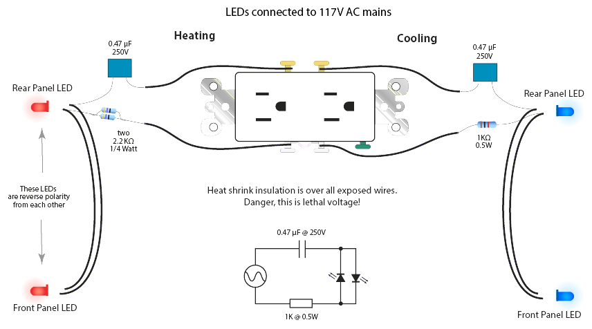
I know exactly which site that schematic came from.
I wouldn't go that route, but it should work...for awhile, at least, until an LED breaks down from the reverse voltage...
Cheers!


![Craft A Brew - Safale S-04 Dry Yeast - Fermentis - English Ale Dry Yeast - For English and American Ales and Hard Apple Ciders - Ingredients for Home Brewing - Beer Making Supplies - [1 Pack]](https://m.media-amazon.com/images/I/41fVGNh6JfL._SL500_.jpg)


And incur the voltage drop
I wouldn't go that route, but it should work...for awhile, at least, until an LED breaks down from the reverse voltage...
Cheers!
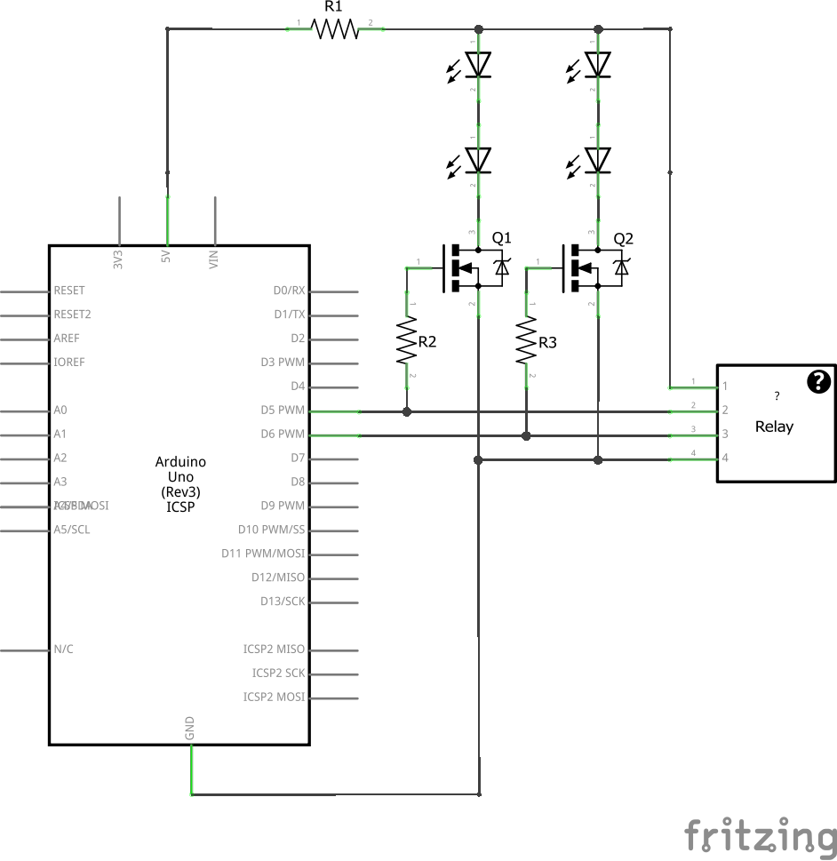
A cheap n-channel FET with a TTL compatible gate (eg: 2N7002) and wired from 5V through say a 220 ohm resistor to an LED would be a safe, sane and long-lived solution. Even a cheap FET such as the 2N7002 has RDS(on) spec in the single-digit ohm range - you're not going to notice the drop at the LED
Cheers!
love this controller. beer still fermenting at 18 degC with outside temp 43, cool.
Not sure I'm following that.
Got a napkin sketch for me? I'm out of my prehistoric audio circuit comfort zone here.
What's driving the FET 's gate? And what's powering the LED?
..Todd


DISCLAIMER: I haven't had a lick of electronics classes, instruction, or training.
but if we're using the sainsmart relay where the input pins are inverted wouldn't we need to use pnp transistors?
The inversion occurs after the relay inputs though, doesn't it.
It'd be more useful to have the indicator on the relay outputs though, so you can see if the relay board's output is alive.
I believe that the relay pins are high in the off state and low in the on state, so it's when the current stops on pins 5 or 6 that is when the relay kicks on.
But it's the logic state that's inverted, not the polarity, right? The voltage is still +5v. (I'm referring to the question about using PNP devices.)
I do have some nixie tubes in my junk box. Hmm... Nah, retro isn't going to fit in my box.
..Todd
I wonder how large they will let this thread go before they lock it to make a new oneWe gotta be getting up there by now...
But I see that someone has gone in and deleted all the unrelated posts in there. It's only 75 pages now.
Attached drawing is what I was thinking.
DISCLAIMER: I haven't had a lick of electronics classes, instruction, or training.
WARNING: Follow my schematics at your own risk!
I only post this drawing because I'm thinking of doing the same thing my self.
day_trippr, I drew the schem with npn transistors as you suggested, but if we're using the sainsmart relay where the input pins are inverted wouldn't we need to use pnp transistors?
Wouldn't the opposing polarity of the diodes alleviate the reverse voltage across the currently inactive one?
And yeah, I am trying to avoid drawing more VCC current from the Arduino pins.
LEDs are not actually diodes in the sense that they are not designed to tolerate inverse voltage like actual diodes are. While a diode might have a PIV tolerance in the many hundreds of volts, in fact many LED specs don't even state a PIV tolerance, and the ones that do almost always use the forward voltage with a note limiting the available current to a few microamps.
In the proposed application there will be periods where neither diode is fully conducting, and in those periods one of the LEDs will be seeing inverse voltage with the potential current well in excess of microamps.
Cheers!
I wonder how large they will let this thread go before they lock it to make a new oneWe gotta be getting up there by now...

microamps.
In the proposed application there will be periods where neither diode is fully conducting, and in those periods one of the LEDs will be seeing inverse voltage with the potential current well in excess of microamps.
Cheers!
Milliamps? I dont think microamps will light a standard LED but I could be wrong.
Hey day_trippr, I'm loving your electronics expertise here. Do you see any room for subtle improvement in the basic schema I presented for running LEDs on 110VAC, to extend the life of the LEDs? Maybe a Schottky or FRED in parallel with the LED to speed up that near-cut-off reverse voltage situation? (I'm totally guessing, no training here at all.) Or anything else you can think of that would improve that particular situation?
..Todd