HELP needed

Homebrew Talk - Beer, Wine, Mead, & Cider Brewing Discussion Forum

Help Support Homebrew Talk - Beer, Wine, Mead, & Cider Brewing Discussion Forum:

This site may earn a commission from merchant affiliate links, including eBay, Amazon, and others.

new2brew1221

Well-Known Member
Joined
May 29, 2012
Messages
275
Reaction score
8
Built my keezer, but am stumped on how to wire the temp controller!! If someone could tell me where the white, black and green wires go, from the locations on the controller, and the locations on a standard outlet, using a standard drop cord for the wire, I would GREATLY appreciate it!! I cannot find any diagrams using this controller.
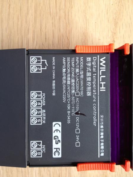
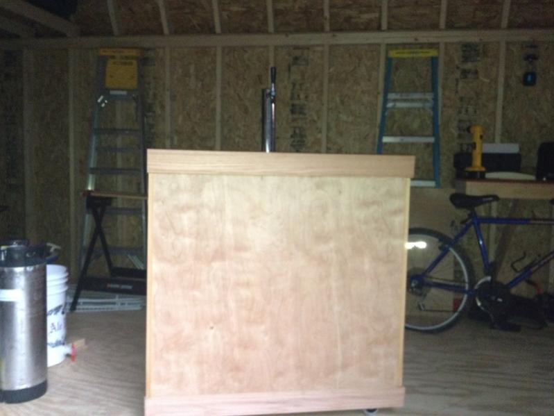
image-2840184938.jpg


image-3884418004.jpg
 
Cut a three prong extension cord where it makes sense for your installation. Inside there will be black (hot) white (return or "neutral") and green (safety ground). The male end supplies power to the Willhi controller, and you'll plug your fridge into the female end.

Then, just follow the diagram...

willhi.jpg


Cheers!
 
Sorry....Engineering Technician. I read and draw electrical schematics and write technical manuals. Missed the dots on your other terminations... :D :mug:
 
38 years designing computers, memory subsystems and solid state disks for the likes of IBM, Digital, HP, Compaq, Stratus, and now a hired gun doing 3rd generation PCIe SSDs. Extensive patent portfolio, primarily on caching algorithms, error correction, enhancing memory exchange transactions and fault isolation mechanisms.

Even when I was hand drawing schematics in the early 70s I never resorted to "jumping over" wires, or using dots for a three line connection as the one shown. Amazingly, everyone I ever worked for understood it perfectly - and they still do ;)

Cheers!
 
Oh....That explains everything! You're an Electronics Engineer. For a novice who doesn't know how to connect a well labled electronic thermal controller, I thought it best to show there was no connection before he created a neat little short circuit. Congrats on your 38 year career, I only did 33....Now, I just brew! Isn't life great? :D

:mug:
 
Ok, so if I'm reading this right, then it should be white from extension cord to 4 and from 4 to silver tab on outlet. Black from extension cord to 1, from 1 to 3, and from brass tab on outlet to 2. Green to ground on outlet. Plus, I need to cut the connector tab on the silver side?
 
Thanks for the help. I'm just trying to be able to control the temp on my new keezer.
 
If you are using a Duplex outlet, but why not just use a dedicated single gang recepricle?

Here is another option if you are using a Duplex outlet...That way, you don't have to modify the recepticle.

power.jpg
 
Ok, so if I'm reading this right, then it should be white from extension cord to 4 and from 4 to silver tab on outlet. Black from extension cord to 1, from 1 to 3, and from brass tab on outlet to 2. Green to ground on outlet. Plus, I need to cut the connector tab on the silver side?

You have everything right except the need to cut the connector tab (which - if you're determined to do that - should really be done on the brass connector tab to isolate the hot side instead of isolating the neutral side). That controller is only a single stage, so it can control a cooling device or a heating device, but not both at the same time, so there's no real need to split the dual outlet.

Further, to me it would make more sense to just buy an inexpensive three prong extension cord, cut it somewhere between the two ends, and save yourself the extra expense of the outlet, box, and faceplate...

Cheers!
 
The OP was obviously concerned about the second female recepticle being hot when the temp controller calls for cooling. He mentioned modifying the recepticle, which is very difficult and often results in cracking the body of the outlet.

A safety cover would remind one, that the other outlet is not to be used.

Oh....It was my Skullcrusher IPA..Mmmmmmm!! :D
 
Oh....That explains everything! You're an Electronics Engineer. For a novice who doesn't know how to connect a well labled electronic thermal controller, I thought it best to show there was no connection before he created a neat little short circuit. Congrats on your 38 year career, I only did 33....Now, I just brew! Isn't life great? :D

:mug:

You may be right about clarity in this case, but that's like the fifth or sixth similar diagram I've posted up in the forums and so far none of the victims has been reported to have died ;)

Life is indeed great! I actually had retired for a few years, but after running out of projects around my house, our 2nd house in the White Mountains, my sons houses, and my mom's house, then spending a couple of years flyfishing my way across the country, I got bored enough to accept an offer to do design work from home, and I've been having a ball. It still leaves me plenty of time to keep the pipeline full, and I can drink on the job! :rockin:

Cheers!
 
day_trippr said:
You have everything right except the need to cut the connector tab (which - if you're determined to do that - should really be done on the brass connector tab to isolate the hot side instead of isolating the neutral side). That controller is only a single stage, so it can control a cooling device or a heating device, but not both at the same time, so there's no real need to split the dual outlet.

Further, to me it would make more sense to just buy an inexpensive three prong extension cord, cut it somewhere between the two ends, and save yourself the extra expense of the outlet, box, and faceplate...

Cheers!

I was just thinking, that by cutting the tab, I could use it for a lamp or something. If I could leave the tab, and still have a functioning receptacle, then I would just leave it. I am planning on putting the temp controller in the side of the cabinet I built around the freezer, with the outlet further down on the side. I just want to make sure everything is wired correctly and not have to worry about shorting anything out. Thanks for the help.
 
I was just thinking, that by cutting the tab, I could use it for a lamp or something. If I could leave the tab, and still have a functioning receptacle, then I would just leave it. I am planning on putting the temp controller in the side of the cabinet I built around the freezer, with the outlet further down on the side. I just want to make sure everything is wired correctly and not have to worry about shorting anything out. Thanks for the help.

Ok, that makes sense. After removing the brass tab between the two duplex outlets, you'll need to run another black/hot wire from the line-in side to the brass screw for the socket not connected to the Wihill controller. That'll give you the dual-purposed duplex outlet you're looking for. As long as you're not going to plug something with a significant draw (eg: vacuum cleaner) into the "always hot" socket you don't really need to add a separate white/neutral wire...

Cheers!
 
WileECoyote said:
Bump, Anyone know what #5 and 6 terminals are for? I can't read the Chinese printed on them lol

Cheers :mug:

It is most likely a separate power terminal to hook up a separate heating element. I do not have the same controller but that's what the back of my dual stage controller looks like.
 
Bump, Anyone know what #5 and 6 terminals are for? I can't read the Chinese printed on them lol

Cheers :mug:

They're supposedly not meant to be used by the consumer. From the manual "Factory parameter settings of thermostat can be locked after a short circuit; user cannot modify"
 
They're supposedly not meant to be used by the consumer. From the manual "Factory parameter settings of thermostat can be locked after a short circuit; user cannot modify"

'User' in this case means he who will be pressing the buttons - not he who is wiring the controller. Of course, in our case, these two roles are played by the same guy. ;)
 
Cut a three prong extension cord where it makes sense for your installation. Inside there will be black (hot) white (return or "neutral") and green (safety ground). The male end supplies power to the Willhi controller, and you'll plug your fridge into the female end.

Then, just follow the diagram...

willhi.jpg


Cheers!

Thanks will try this hopefully I dont blow somethin up! :rockin:
 
Can I use one on these inside a mini fridge to replace the thermostat dial? I have one fridge that I was able to adjust the temperature on, however the other one i have does not have a screw that is adjustable. I live in Florida and in the middle of summer right now I need to be able to keep my fermentor in an area that stays cool in this awful heat. So far this has worked great for me. Now I would like to be able to get 2 batches going at a time! please help
 
Built my keezer, but am stumped on how to wire the temp controller!! If someone could tell me where the white, black and green wires go, from the locations on the controller, and the locations on a standard outlet, using a standard drop cord for the wire, I would GREATLY appreciate it!! I cannot find any diagrams using this controller.

It looks like I have the exact same model except mine is WH7016F. It says F instead of C and it reads in Fahrenheit. The writing on the back looks exactly the same. Would I presume that the wiring is the same. Does anyone know?
 
Can I use one on these inside a mini fridge to replace the thermostat dial?[...]

You could, by removing what should be a pair of low voltage connections at the internal controller and routing them through the relay contacts of the WillHi or equivalent controller. But you'd have to bring 110VAC into the interior of the fridge to power the WillHi. I'd think it would be easier to simply short out the internal controller/thermostat and use the WillHi externally, just bring the probe wire into the fridge...

Cheers!
 

Latest posts

Back
Top