Yet another PID Problem Thread

Homebrew Talk - Beer, Wine, Mead, & Cider Brewing Discussion Forum

Help Support Homebrew Talk - Beer, Wine, Mead, & Cider Brewing Discussion Forum:

This site may earn a commission from merchant affiliate links, including eBay, Amazon, and others.

SanduskyRiver

Member
Joined
Oct 14, 2015
Messages
20
Reaction score
2
I have a gas system controlled by a Mypin TA4 with two Auber PT100 RTD probes. I have a DPDT toggle to switch between them - one direction for HLT and one for HERMS. Since inception I have struggled with accurate temp measurements. I can adjust the PID correction factor to match an external thermometer only to find it off again later, often 30 degrees F or more. I wired the toggle according to info from Auber. Checking the PID setup I overlooked the input type and it was defaulted to K and not RTD. Before I could do the happy dance to celebrate the solution to my problems the display now reads LLLL. I spent a good portion of today reading past postings and watching PID videos (yawn) to no avail. I tried various suggestions of jumper wires and reversing polarity and all I succeeded in was sweating a lot and changing LLLL to UUUU and back again. I swapped leads, swapped RTDs, wired one directly to avoid the switch, all to no avail. If I change the input back to K I get numbers again, although of questionable reliance. Anyone else suffer the same fate and find a conclusive answer? Many thanks for your help.
 
How many leads do your RTD probes have?

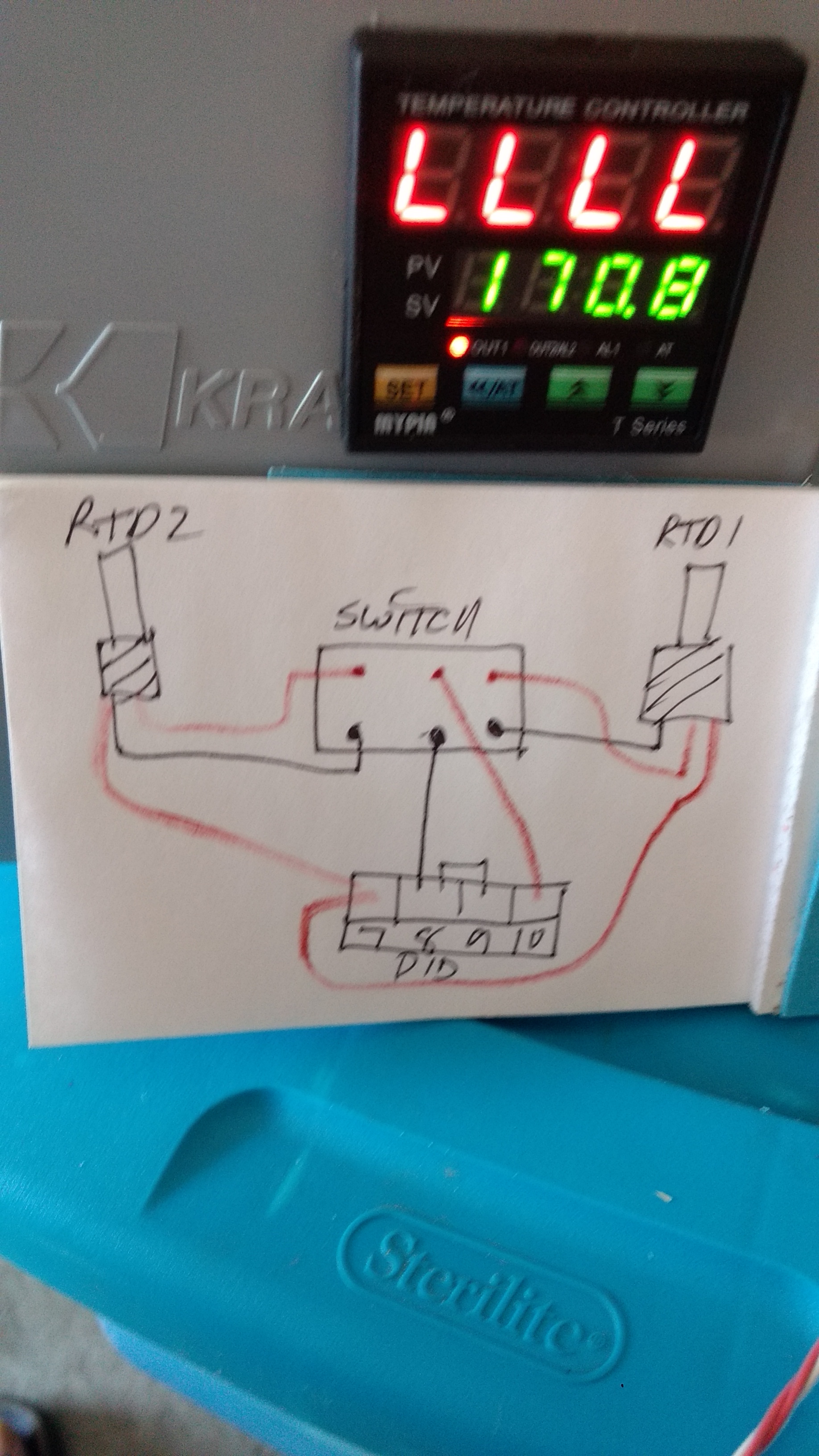
Do you have a schematic you can post of your RTD switching and connection to PID?

What make and model switch are you using to switch between RTD's?

Brew on :mug:
 
How many leads do your RTD probes have?

Do you have a schematic you can post of your RTD switching and connection to PID?

Three wire RTD, two red and one white. Forgive my schematic skills but I think you'll get the point. Black line represents the white lead.
IMG_20180528_174103424.jpg

What make and model switch are you using to switch between RTD's? Big box store brand toggle, nothing in particular.
 
It's been a while since I wired mine, but I think the problem is that you have terminals 7 and 10 connected together. Try connecting one red from each sensor to terminal 7, and keep the other red wires from the sensors to the switch as you have them. Add a wire connection from the center pole of the switch on the red wire side, to terminal 10.
 
The second schematic should work, but the first was definitely wrong. Are you sure that you haven't got any of the RTD wires mixed up at the switch terminals?

If wired according to the second schematic, then the switch itself could be the problem. Measuring temps with an RTD requires measuring milli ohm differences in resistance values. If the contact resistances of all four contact pairs in the switch are not equal and stable, then you will get flaky readings. Auber sells a switch specifically recommended for RTD switching. If you can't figure anything else out that is wrong, try the recommended switch.

Brew on :mug:
 
Last edited:
Good to know about the Auber switch. Looks like something well worth the price. Thanks for the recommendation
 
Type K is the default, it’s a thermocouple so generates millivoltage as temperatures change. RTD is a resistive temperature device, it’s a resistor and all resistors change some with temperature. You need to use the right RTD too. Your controller may want a different calibration curve. I would start by just hooking up a single RTD to the controller first to ensure you are wiring it correctly. A 3 wire RTD has to be wired correctly, if the LLLL is the temp indicator it sounds like you have a red wire where the black should be. The two reds go to one side of the RTD, the black to the other so instead of seeing 100 ohms or so it is seeing a short.
 
Type K is the default, it’s a thermocouple so generates millivoltage as temperatures change. RTD is a resistive temperature device, it’s a resistor and all resistors change some with temperature. You need to use the right RTD too. Your controller may want a different calibration curve. I would start by just hooking up a single RTD to the controller first to ensure you are wiring it correctly. A 3 wire RTD has to be wired correctly, if the LLLL is the temp indicator it sounds like you have a red wire where the black should be. The two reds go to one side of the RTD, the black to the other so instead of seeing 100 ohms or so it is seeing a short.
he may have possible damaged them like you say with the k input but Ive wired up many of these and used the same type of DKC brand rtds only I bought all mine from ebay and never had an issue once I switched them to the right probe type.
I believe the wiring schematics in the manuals are wrong for one of the mypin units but I cant remember if it was the ta4 or TD4 models. in any case the sticker on the actual unit has the correct pinouts.

also keep in mind the two red wires need to be exactle the same length and have the same resistance as they work as sort of a check system against each other as a reference point. so having one go through switch contacts and not the other should result in strange readings if any.
 
Last edited:
I doubt hooking it up wrongwould hurt anything as long as it was just inputs. Good point on length of the red leads, iactually all of them should be the same. The black lead carries current and is part of the measurement; one red lead supplies current, the other is to measure.
 
...

also keep in mind the two red wires need to be exactle the same length and have the same resistance as they work as sort of a check system against each other as a reference point. so having one go through switch contacts and not the other should result in strange readings if any.
Good point. I forgot the part about all the leads needing to be the same length for proper operation. Which is also why if you are going to switch between probes, you want all the leads to be switched. You can have the circuit work electrically by only switching two leads, but it won't work for precision resistance measurement.

Brew on :mug:
 
Following up on my original post, I checked all my leads one by one and I had two crossed. When I soldered the quick disconnects I transposed pin 1-3. Strange thing is I did this on both leads, same mistake twice or copied one off the other. I corrected the mistake and no more UUUU or LLLL errors. Thanks for the support of everyone that replied.
 
Back
Top