HarpuaScorpio
Well-Known Member
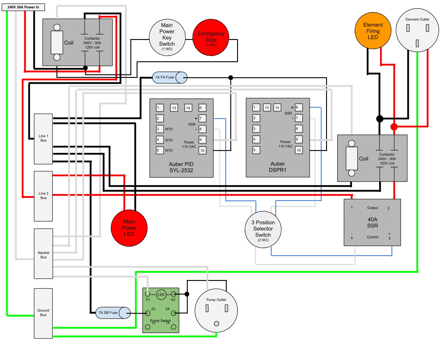
I based this mostly off of one of P-J's popular diagrams but with ideas and input from various other places on this forum. I wouldn't mind some feedback and a double check on the diagram, if you don't mind.
Here's the goals of this system:
-Indoor 240V 30A recirculating eBIAB w/ 5500W Stainless Element from Bobby
-Switching power to the element between PID (SYL-2352) for mashing and DSPR1 for ease and precision of boil control. LED to show when there is power hitting the element.
-Key switch main power with E-Stop breaking the two hot lines going in to the panel (not tripping the GFI Breaker like in P-J's designs). LED to show panel is powered on.
-The pump switch (Auber SW1) is illuminated when the pump is running, eliminating a stand alone LED.
Here's the diagram:
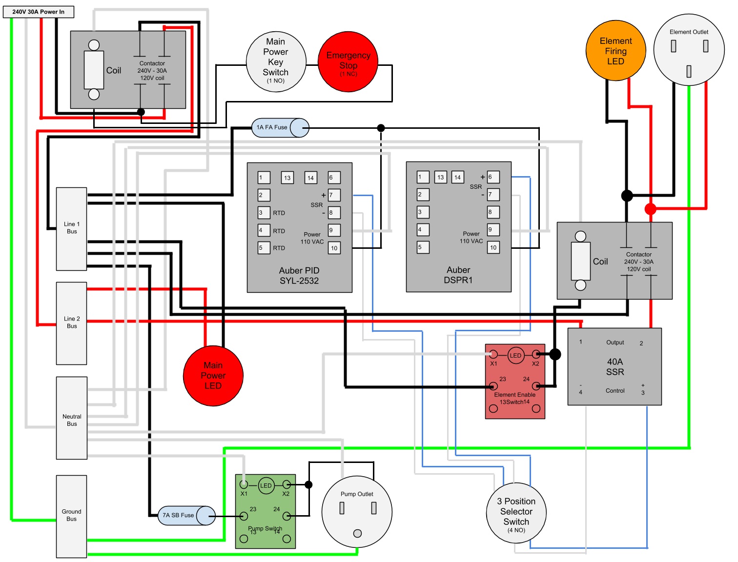
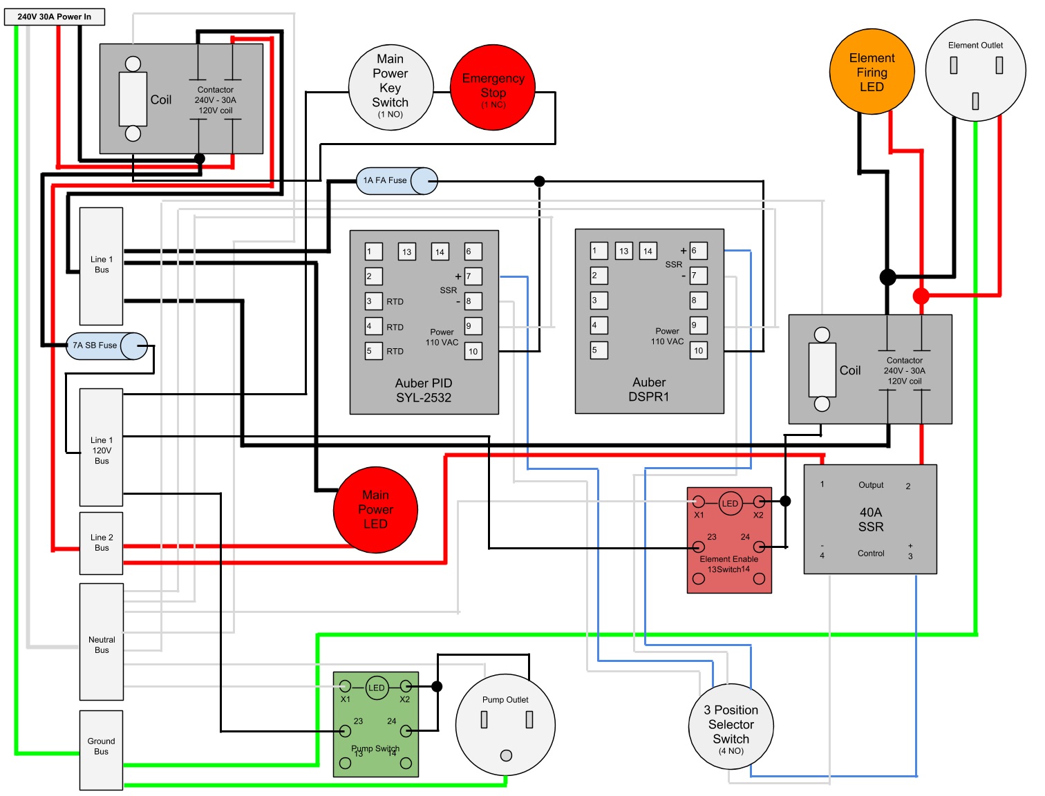
I also have a question about the necessity of the contactor. I understand that it physically breaks the connection, ensuring that no power is hitting the element but I've also read that the DSPR1 can fire the element very quickly, almost strobe-like. Wouldn't that be harmful to the contactor? I've drawn up another diagram that basically eliminates the contactor and connects the SSR directly to the element and LED.
Thanks in advance.
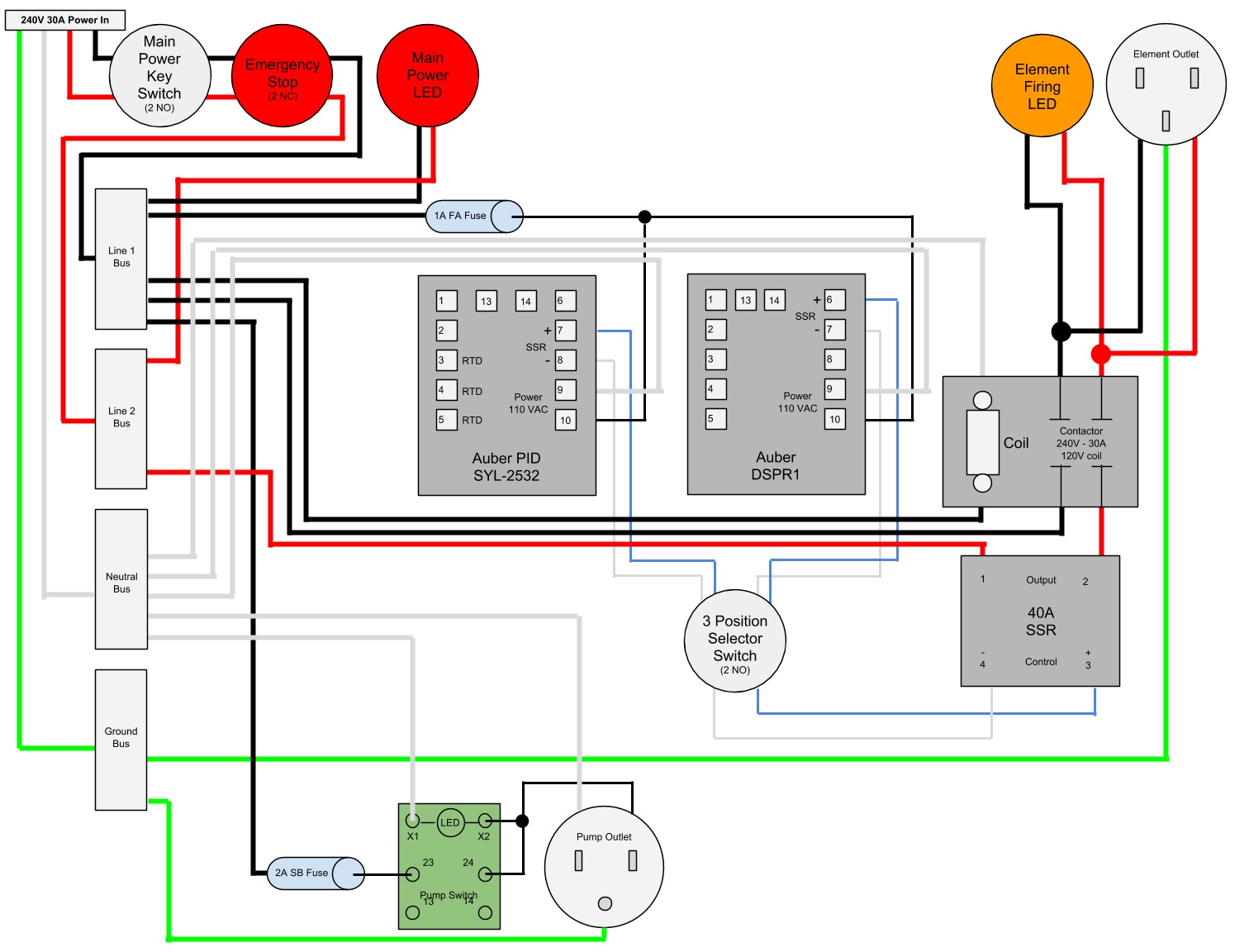
Here's the goals of this system:
-Indoor 240V 30A recirculating eBIAB w/ 5500W Stainless Element from Bobby
-Switching power to the element between PID (SYL-2352) for mashing and DSPR1 for ease and precision of boil control. LED to show when there is power hitting the element.
-Key switch main power with E-Stop breaking the two hot lines going in to the panel (not tripping the GFI Breaker like in P-J's designs). LED to show panel is powered on.
-The pump switch (Auber SW1) is illuminated when the pump is running, eliminating a stand alone LED.
Here's the diagram:
I also have a question about the necessity of the contactor. I understand that it physically breaks the connection, ensuring that no power is hitting the element but I've also read that the DSPR1 can fire the element very quickly, almost strobe-like. Wouldn't that be harmful to the contactor? I've drawn up another diagram that basically eliminates the contactor and connects the SSR directly to the element and LED.
Thanks in advance.