Wiring Diagram Check Please

Homebrew Talk - Beer, Wine, Mead, & Cider Brewing Discussion Forum

Help Support Homebrew Talk - Beer, Wine, Mead, & Cider Brewing Discussion Forum:

This site may earn a commission from merchant affiliate links, including eBay, Amazon, and others.

Antonio Martinez

Well-Known Member
Joined
Apr 14, 2018
Messages
133
Reaction score
83
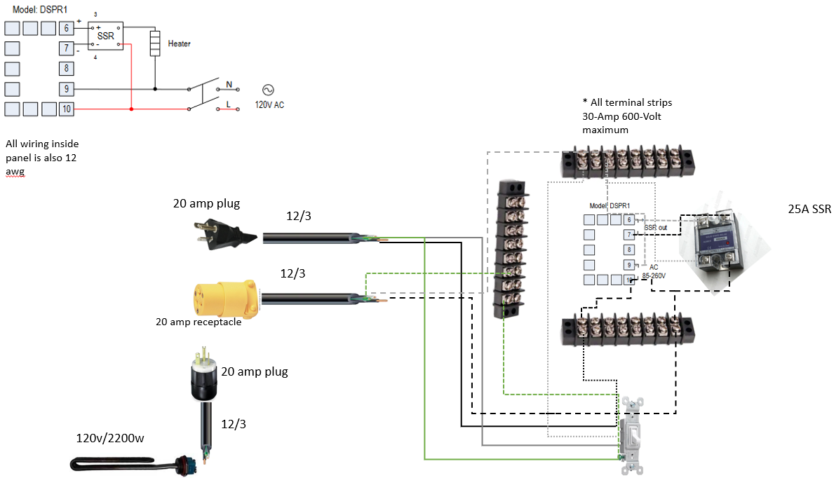
Looking for a double check on the layout/wiring. The system will be a 120v 2200w control panel based on DSPR1 controller from Auber. This will be plugged into a dedicated 20a GFCI protected circuit and will not run anything else (i.e. no pump outlet in the control panel). The heatsink for the SSR is actually going to be oversized and intended for 40a SSR but in the event an upgrade is done I'm trying to cut down on the parts needing to be replaced. All wiring will be 12 awg wire for simplicity even though I understand smaller gauge wire could be run to the DSPR itself. I am also planning to use terminal strips rated to 30a 600v as hot, neutral, ground bus bars to simplify wiring and make it easier to add any future connections. Jumper wires will be used to make connections between lugs on the bus bars.

Cheers
 

Attachments

  • 120v 2200w Control Panel.PNG
    120v 2200w Control Panel.PNG
    283.1 KB · Views: 69
You will likely have arcing issues plugging and unplugging an 18.3A live load. You can mitigate this by always turning the power setting to 0 prior to unplugging. Also, if your SSR fails, you have no way to cut power to the element except unplugging the controller or element, accompanied by arcing. Arcing can damage plugs and outlets.

Brew on :mug:

Appreciate your looking it over. I planned to turn the power to 0 before unplugging the controller but would physical switches for both power to the controller and element be better?
 
The DSPR uses very little current, so arcing on plugging/unplugging will be non-existent. I do recommend a switch on the hot line that feeds the SSR.

Brew on :mug:
 
Attached is an updated version, hopefully the wiring is a little easier to distinguish in this one. I added the switch as you recommended, if you wouldn't mind letting me know if its setup correctly I'd appreciate it. Thanks again.
 

Attachments

  • 120v 2200w Control Panel v2.PNG
    120v 2200w Control Panel v2.PNG
    217.5 KB · Views: 31
Can't really follow the drawing very well. Looks like you might have the hot and neutral both connected to the SSR AC terminals (but not the same terminal.) If so, this is incorrect, and would instantly fry the SSR.

Also looks like you have both hot and neutral going to the switch, which you would only do for a double pole switch. For a single pole switch (most common type) only the hot goes to the switch. What type of switch are you using (mfg and PN if possible)?

Brew on :mug:
 
Doug,

Its a Leviton 54521-2W 20-Amp from amazon I haven't purchased it yet so if you have something that might serve me better I'm open to it. Not the best at designing circuits and the diagram provided by Auber is a bit vague at least to me. Correct me if I'm wrong but in the diagram at the top right they show the neutral running to positive on the SSR and hot to negative. As I've read elsewhere it wouldn't be the first time Auber mixed up their diagram. My basic desire is to run a single 2200w immersion heater controlled by the DSPR1 and implement your suggestion of a physical switch to shut off power to the element out. I'll link the parts below. The incoming power cord and GFCI I already have and are not listed below. Thank you for all your help and responses.

Leviton 54521-W 20 amp switch
DSPR1
2200w element
20 amp plug (element power to control panel)
20 amp receptacle (element power out)
25a SSR
40a Heat Sink
Project Box
terminal strips
Auber's drawing while topologically correct, is confusing. The top wire coming from the SSR to the element should be red. (The electrons don't care what color the wires are. The colors are just to make things easier for humans to figure out and troubleshoot.)

Also, Auber's drawing was originally for a 240V, split phase application, and they didn't fully modify it for a 120V application. There is no need to switch the neutral wire in a 120V system, but when you have two hots in a 240V system, you need to switch both hots. Thus you only need a single pole switch for a 120V system. Your selected switch is single pole, so will work for you.

I'll put together a better drawing for you.

Brew on :mug:
 
I looked around a bit before settling on that leviton switch and didn't see others rated for 20a but I know its done since I see them in prebuilt & diy systems frequently. Function is more important to me than the aesthetic though so I'm okay with keeping it. I would really appreciate a new diagram. This community owes you and others who have lent their knowledge to guys like me trying to put together their own builds.
 
I looked around a bit before settling on that leviton switch and didn't see others rated for 20a but I know its done since I see them in prebuilt & diy systems frequently. Function is more important to me than the aesthetic though so I'm okay with keeping it. I would really appreciate a new diagram. This community owes you and others who have lent their knowledge to guys like me trying to put together their own builds.
Some of the switches you see are probably Leviton 3032's. These are double pole, 30A switches that are suitable for use with 240V systems.

Brew on :mug:
 
I found a possibly better switch based on what you're saying, its a rocker switch rated to 20A/125 VAC and the only mention of a model number on Aubers site is KCD2 but no mfg information. Reworked the diagram a bit and added a background and made neutral purple so its easier to see than white/yellow. I was also able to find an image that shows the positive and negative terminals on the Auber SSR and labeled the in and output based on that information.
 

Attachments

  • 120v 2200w Control Panel v3.PNG
    120v 2200w Control Panel v3.PNG
    228.4 KB · Views: 13
I found a possibly better switch based on what you're saying, its a rocker switch rated to 20A/125 VAC and the only mention of a model number on Aubers site is KCD2 but no mfg information. Reworked the diagram a bit and added a background and made neutral purple so its easier to see than white/yellow. I was also able to find an image that shows the positive and negative terminals on the Auber SSR and labeled the in and output based on that information.
The connectivity on that drawing is still messed up. I'll get a drawing out later today.

Brew on :mug:
 
Just a suggestion, get rid of the terminal strips and just use wirenuts. Based on the way you have the lines hitting them, I think you think they work a different way. The screws on any given strip are not all electrically connected together. Only the pairs are connected so connecting pair one to pair two requires a jumper wire. In the end you'll have a bunch of unnecessary connections to make it "simple".

diagram.jpg
 
Note that you can tap the hot line to feed the DSPR1 EITHER from where I show it in the picture before the switch or you can tap on the right (switched) side. That's up to you. In the picture the display on the DSPR1 will be lit up when it's plugged in. The switch then becomes an element enable/disable. If you tap after the switch, the switch acts more like a main power on/off.
 
Note that you can tap the hot line to feed the DSPR1 EITHER from where I show it in the picture before the switch or you can tap on the right (switched) side. That's up to you. In the picture the display on the DSPR1 will be lit up when it's plugged in. The switch then becomes an element enable/disable. If you tap after the switch, the switch acts more like a main power on/off.
Bobby, I think the terminal strips are what's confusing me trying to make sure I get everything tied together with them. I'd hoped it would be a smart add in the event I ever decided to add a 120v outlet in the future and make the wiring cleaner.
 
The connectivity on that drawing is still messed up. I'll get a drawing out later today.

Brew on :mug:

I figured it would still have issues. Like Bobby mentioned I think the terminal strips are making me go cross eyed trying to follow the connections through my diagram.
 
Note that you can tap the hot line to feed the DSPR1 EITHER from where I show it in the picture before the switch or you can tap on the right (switched) side. That's up to you. In the picture the display on the DSPR1 will be lit up when it's plugged in. The switch then becomes an element enable/disable. If you tap after the switch, the switch acts more like a main power on/off.
The potential issue with switching the power to the DSPR is that it comes up in the same state as it was when powered off. This could lead to the element coming on before you can set the DSPR appropriately, and could lead to dry firing the element. You are more likely to remember to properly set the DSPR if it comes on before the element gets enabled. If you want to switch the DSPR, you can implement that with additional switches, and even implement a safe start interlock. But this requires more hardware.

Brew on :mug:

My personal preference, without having used one of these systems, would be to allow the DSPR to receive power when the controller is plugged in and manually control power to the element. My logic is that the DSPR itself already has an on/off capability built in.
 
Ok, here's my take on a design for OP. I added an "Element Firing Light" as it is the quickest way to know that your SSR has failed. If it is on when the SSR should be off, then your SSR has failed, either temporarily because it got too hot, or permanently. I also showed how to add a fuse if you don't want to use 12AWG wire to connect to the DSPR1. Fuse is not needed if 12AWG wire is used.

DSPR1 120V Simple.PNG


Brew on :mug:
 
Doug, I really appreciate it. I apparently also misunderstood the SSR wiring and thought the neutral from the main source was fed through it as well. I really appreciate this and it makes more sense looking at it now. I will keep the panel wiring 12 gauge but will definitely incorporate the light. No reason not to have some indicator as to whether the SSR is being powered unintentionally.
 
Last edited:
One odd behavior you might run into with the element on light is that if you test the control panel without the element connected, the light will come on (usually dimmer than normal.) This is due to the electrical characteristics of SSR's.

Brew on :mug:
 
Bobby, I think the terminal strips are what's confusing me trying to make sure I get everything tied together with them. I'd hoped it would be a smart add in the event I ever decided to add a 120v outlet in the future and make the wiring cleaner.

If you absolutely want to use the terminal strips, just use one of them. Like I mentioned, each pair of screws are connected and those molded plastic walls separate them. In a controller this simple though, just use any screw terminals that happen to be present to tap off. When you cant, just use wirenuts.
 
If you absolutely want to use the terminal strips, just use one of them. Like I mentioned, each pair of screws are connected and those molded plastic walls separate them. In a controller this simple though, just use any screw terminals that happen to be present to tap off. When you cant, just use wirenuts.

Not sure why I didn't realize they were paired vertically like that. I was originally thinking joining any of the screw terminals required jumper wires.
 
Not sure why I didn't realize they were paired vertically like that. I was originally thinking joining any of the screw terminals required jumper wires.
Also, they make small, flat, kind of "U" shaped jumper connectors to connect the vertical pairs horizontally. Much easier than using wires to jumper pairs.

Go to "images.google.com" and search for "terminal strip jumpers" to see several different varieties.

Brew on :mug:
 
Also, they make small, flat, kind of "U" shaped jumper connectors to connect the vertical pairs horizontally. Much easier than using wires to jumper pairs.

Go to "images.google.com" and search for "terminal strip jumpers" to see several different varieties.

Brew on :mug:

Thanks for the tip. I found some on Amazon that are 5 position jumpers. Would there be any issue with breaking them to into say 2 or 3 position depending on my need?
 
Thanks for the tip. I found some on Amazon that are 5 position jumpers. Would there be any issue with breaking them to into say 2 or 3 position depending on my need?
Cutting/breaking them shouldn't be an issue. Just make sure there are no burrs left that could short to adjacent terminals. Leaving an empty pair of terminals between terminals on different nets would make shorting pretty much impossible, even with burrs.

Brew on :mug:
 
Cutting/breaking them shouldn't be an issue. Just make sure there are no burrs left that could short to adjacent terminals. Leaving an empty pair of terminals between terminals on different nets would make shorting pretty much impossible, even with burrs.

Brew on :mug:

I couldn't think of any reason it would but I figured I'd ask the question. Hopefully I'll be able to get all the parts soon and get everything put together. I already sold my propane burner so I'm all in on the electric setup.
 
sorry if i missed it, but a 20 amp breaker is really only good for 80% of the load.
so we like to figure 16amps a circuit thats the same for a #12 wire. your running 18.3 on an element.
I would at least use #10 thhn. just my two pennies worth
 
sorry if i missed it, but a 20 amp breaker is really only good for 80% of the load.
so we like to figure 16amps a circuit thats the same for a #12 wire. your running 18.3 on an element.
I would at least use #10 thhn. just my two pennies worth

My understanding based on the reading I've done is that the 80% load is based on continuous operation, which in brewing application doesn't apply. I'm definitely not an expert or authority on this so take that with a grain of salt. Just sharing what I've seen to be a consensus.
 
usually 3 hours for a continuous load so you are right in that, but I would still go larger to cut down on the load on the wires. I havent wired my own brew controller, but have worked on commercial ovens and have seen wires burnt from overloading. not trying to say anyone is wrong, you probably wont have an issue.
 
Back
Top