
- Joined
- Jul 21, 2013
- Messages
- 1,317
- Reaction score
- 305
Ok, so I randomly bought this switch when getting other things because it looked neat. LOL. It turned out to be pretty damn big. Anyway, it is the replacement to the mushroom emergency off because that thing just frikken fell apart on me in my test set up.
It looks kinda like this, but mine has start and stop labeled on the buttons:
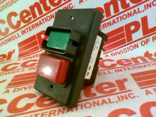
Here is the only wiring info I can find based on many clicks through the interwebz:
http://cdn0.grizzly.com/manuals/h8243_m.pdf
I am only running 110/120v so I figure I am running black from my wall wire to the Line side? Then black from the load side out to my power block? Do I need to run the neutral from my wall wire to the switch as well...and then to the neutral block? Now that I write this out it sounds right.
(What I think confused me is I tried to wire the wall to the power block and the block to the switch. That would have worked for only one device instead of whole control panel.)
PJ, if you see this, I am assuming the switch is powerful enough to run a 120v element at 20 amps.
It looks kinda like this, but mine has start and stop labeled on the buttons:
Here is the only wiring info I can find based on many clicks through the interwebz:
http://cdn0.grizzly.com/manuals/h8243_m.pdf
I am only running 110/120v so I figure I am running black from my wall wire to the Line side? Then black from the load side out to my power block? Do I need to run the neutral from my wall wire to the switch as well...and then to the neutral block? Now that I write this out it sounds right.
(What I think confused me is I tried to wire the wall to the power block and the block to the switch. That would have worked for only one device instead of whole control panel.)
PJ, if you see this, I am assuming the switch is powerful enough to run a 120v element at 20 amps.
