[Version 2 Release] RaspberryPints - Digital Taplist Solution

Homebrew Talk - Beer, Wine, Mead, & Cider Brewing Discussion Forum

Help Support Homebrew Talk - Beer, Wine, Mead, & Cider Brewing Discussion Forum:

This site may earn a commission from merchant affiliate links, including eBay, Amazon, and others.
Thanks for previous responses! I've been trying to tap kegs for the last half hour, but nothing shows up, no matter what status I set for the keg before putting it on tap. Am I missing something obvious? TIA!
 
Thanks for previous responses! I've been trying to tap kegs for the last half hour, but nothing shows up, no matter what status I set for the keg before putting it on tap. Am I missing something obvious? TIA!

Are you doing a "Flow Meter" install or a "non-Flow Meter" install?

If the former, you need to specify the AlaMode pin to be associated with the tap, otherwise the keg will not be listed in the Tap List screen.

If the latter, you might need to replace /var/www/admin/includes/models/tap.php with the updated version on Github here.
Don't forget to fix the ownership/rights to match the other files in the same folder...

Cheers!
 
If the latter, you might need to replace /var/www/admin/includes/models/tap.php with the updated version on Github here.
Don't forget to fix the ownership/rights to match the other files in the same folder...

Cheers!

Thanks. It's the latter (without flowmeters). I'll try to do what you said.
 
Thanks. It's the latter (without flowmeters). I'll try to do what you said.

Edit: Okay, went to link. How do I download the .php file? I just see an edit window.
 
Probably easier to fetch the file from here, then right-click and Save As...

Cheers!

OMG. I just got it but my fingers on the tiny keyboard ended up saving it as tap_form.php. Where can I get a replacement tap_form.php? TIA!
 
OMG. I just got it but my fingers on the tiny keyboard ended up saving it as tap_form.php. Where can I get a replacement tap_form.php? TIA!

LOL! Meh, stuff happens.

You can grab a new tap_form.php from this folder, and noting that tap_form.php resides in /var/www/admin, whereas tap.php goes in /var/www/admin/includes/models/.

Cheers!
 
fwiw, I inserted a 240 ohm 1/4w resistor in the 5V feeds to all six meters, then had to test them, of course. Pour two neat ounces, send 'em home, move to the next tap, repeat five times. Woof! :drunk:

Anyway, the meters work same as before, and will likely last a lot longer...

Cheers!
 
Is this required?

I would say yes, definitely. Some might want to argue the point, but the fact is that without a current limiting resistor - integrated or discrete - an LED will dissipate more than its rated safe power rating which will shorten its life span.

The fact that the manufacturer puts their recommendation right on the package should inspire compliance, imo...

Cheers!
 
This got me thinking as well. Couldn't find much but found this on Google images which is slightly different. Says in the case of 5v Rs =0. I've emailed SwissFlow for some clarification.
Day_Trippr, are you running a 2.2k between the + and digi pins as well?

swissflow_setup.jpg
 
Probably easier to fetch the file from here, then right-click and Save As...

Cheers!

Okay, I did a right click and save as, then changed the permissions. But I think it must have saved the web page (even though it said save as php) and not the php file itself, because that's what my web server is now serving up...the page that shows the coding for taps.php. So I went to my laptop and tried to do a save as, and apparently saving the file is not an option? Only an htm format save.

Edit: Hot damn. I sucked it up and installed WINSCP. Copied the text for the updated tap.php file from the github source and pasted into a text file, saved as tap.php. Used WINScp to FTP to my raspberry pi. Eureka!
 
fwiw, I inserted a 240 ohm 1/4w resistor in the 5V feeds to all six meters, then had to test them, of course. Pour two neat ounces, send 'em home, move to the next tap, repeat five times. Woof! :drunk:

Anyway, the meters work same as before, and will likely last a lot longer...

Cheers!

How / where did you insert them? Can we see a photo? Thanks! Wether it's "required" or not, it can't hurt to add them.
 
This got me thinking as well. Couldn't find much but found this on Google images which is slightly different. Says in the case of 5v Rs =0. I've emailed SwissFlow for some clarification.
Day_Trippr, are you running a 2.2k between the + and digi pins as well?[...]

Arrgh! I hate conflicting manufacturer information!
I wonder if they changed IR LEDs somewhere along the line?
I'll be interested in reading what SwissFlow has to say.

I did build my breakout board with 2.2K pull-up resistors but have since disconnected them after verifying (with an oscilloscope) that the internal pull-ups on the Arduino - though nearly an order of magnitude weaker - are still sufficient to produce good looking pulse trains...

Cheers!
 
If I understand the purpose behind the resistor, it would be to drop anything over 5v down to that magic 5v area (look at the schematics, you're taking 5 - 24v in, passing it thru the resistor and then sending the 5v on to the meter....)

Coming off the alamode or arduino, you're going to be at 5v anyways so you're not gaining much from adding the resistor (from what I can tell.... I could be wrong).

fwiw, I've been designing computers and associated devices since 1973, and I have always included a current limiting resistor in series with any LED I've ever used (and I've used tons of them). It's basic solid engineering because you never want to feed a bare LED with low impedance power as the LED will draw more current and dissipate more heat than is necessary for it to achieve its nominal rated output. And that is a life-shortening paradigm for any electrical component.

In this specific case there are two "data sheets" that are directly conflicting, with one providing what would be a rather typical application directive (50 ohms per volt) versus another (Vin - 5) * 50 ohms.

The former leaves no wiggle room and requires a current limiting resistor for any applied Vin. The latter suggests that the meter either used an IR LED with an integrated resistor or the module included a discrete resistor, in either case likely 220 to 240 ohms (tolerance type E12 vs E24 with the latter a tiny bit more expensive). This would indeed allow safe operation at 5V without an external resistor; higher voltages would have to comply with the rule as provided.

So...until we know for sure which of the conflicting advisories is the correct one, the safest way to proceed is to go with the 50 ohms per volt rule. It may turn out that there are two generations of meters, one with an integrated resistor, the other without, but unless there was a physical change made along with the functional one, we may not be able to discern which is which.

Anyway...fwiw, here's the front and back of my revised breakout card showing the now-unused pull-up resistors along with the newly added Vin current limiters. R'Pints is still metering just fine...

Cheers!

breakout_board_01.jpg


breakout_board_02.jpg
 
This is AWESOME! Parts are ordered and now in the waiting stage. I had a few questions that I could find "how to" on. I have read all of the previous thread and this one. So, sorry if it has been covered but I haven't seen it.

Questions:
1. How do we integrate Untapped? I think this is a way cool idea.
2. How do we add our labels to the beer. I think it is mcangeli that has it on his tap list. Also, is there a way to link a brew pdf to the label, that way if we are explaining it to a guest we can click on it and go through the brew sheet?

I'm married so bear with me on this last question. Is there a way to have a photo album showing when we don't want to have the list up? The wife is not so stellar on the idea of the list going over the keggerator, its in the kitchen, so I thought it may help ease her mind :)

These are just ideas I have so I'm sorry if they are already being developed or discussed. Thanks to every developer that is working on this project, it is the coolest DIY I have seen yet.

1. Untappd.... I'm planning on releasing the code for untappd in v3. It requires you to have your brewery signed up on untappd (which homebrewers can do) and it requires access to their API so you have to apply for a secret and ID. At the very least, it does require you to have your brewery signed up (You *could* use my api keys as long as you do not adjust the cache rate).

2. the labels and rating for my beers are being linked directly from untappd.

There are a number of additions to the Database that needed to be made in order for this to happen... one of the things I need to do is install a base copy of the untapped code again and make only those changes so that I can create the correct sql schema files...

You should be able to set a screensaver with photos on your pi that comes on (if the monitor is directly hooked to the pi that is) after a set time. You could then use something like the motion sensor hack to knock the screen back to the rpints page or have a mouse attached that you move.
 
Got everything working (without flowmeters version), except... I can't change the background picture. Tried it through the personalization screen, which says the replacement happened, but it never shows up in the real display, even several reboots later. Then I replaced background.jpg directly, but no change. Interestingly, when I 'Restore Default Background' it shows me the picture I copied over, but it never shows up in the real display.

BTW...using WinSCP to manage files is SO much easier than messing around in the Raspian GUI/console with a tiny remote keyboard.
 
Arrgh! I hate conflicting manufacturer information!
I wonder if they changed IR LEDs somewhere along the line?
I'll be interested in reading what SwissFlow has to say.

I did build my breakout board with 2.2K pull-up resistors but have since disconnected them after verifying (with an oscilloscope) that the internal pull-ups on the Arduino - though nearly an order of magnitude weaker - are still sufficient to produce good looking pulse trains...

Cheers!
Thanks for the info on the 2.2k. I'll post back if/when I hear from SwissFlow. If anyone on here happened to purchase factory new, please post up a copy of your instructions! :mug:
 
Got everything working (without flowmeters version), except... I can't change the background picture. Tried it through the personalization screen, which says the replacement happened, but it never shows up in the real display, even several reboots later. Then I replaced background.jpg directly, but no change. Interestingly, when I 'Restore Default Background' it shows me the picture I copied over, but it never shows up in the real display.

Just talking to myself some more... It was the persistent browser cache. CTRL F5 to the rescue.
 
In this specific case there are two "data sheets" that are directly conflicting, with one providing what would be a rather typical application directive (50 ohms per volt) versus another (Vin - 5) * 50 ohms.

The former leaves no wiggle room and requires a current limiting resistor for any applied Vin. The latter suggests that the meter either used an IR LED with an integrated resistor or the module included a discrete resistor, in either case likely 220 to 240 ohms (tolerance type E12 vs E24 with the latter a tiny bit more expensive). This would indeed allow safe operation at 5V without an external resistor; higher voltages would have to comply with the rule as provided.

So I like your logic, based upon blind faith and confidence, plus the idea that it's better to be safe than sorry. Question - you have 6 meters and installed 6 resistors. Any reason why you couldn't have installed 1, and jumpered all your VINs together like you did your grounds? Or did I just show how little I know about electronics? I'm an engineer - honest!
-Kevin
 
1. Untappd.... I'm planning on releasing the code for untappd in v3. It requires you to have your brewery signed up on untappd (which homebrewers can do) and it requires access to their API so you have to apply for a secret and ID. At the very least, it does require you to have your brewery signed up (You *could* use my api keys as long as you do not adjust the cache rate).


2. the labels and rating for my beers are being linked directly from untappd.


There are a number of additions to the Database that needed to be made in order for this to happen... one of the things I need to do is install a base copy of the untapped code again and make only those changes so that I can create the correct sql schema files...


You should be able to set a screensaver with photos on your pi that comes on (if the monitor is directly hooked to the pi that is) after a set time. You could then use something like the motion sensor hack to knock the screen back to the rpints page or have a mouse attached that you move.

Thanks a bunch for the reply and info. I will be patient for v3 for now. Once installed I'm going to give the screensaver the old try and see if it pleases the boss.


Sent from my iPhone using Home Brew
 
1. Untappd.... I'm planning on releasing the code for untappd in v3. It requires you to have your brewery signed up on untappd (which homebrewers can do) and it requires access to their API so you have to apply for a secret and ID. At the very least, it does require you to have your brewery signed up (You *could* use my api keys as long as you do not adjust the cache rate).


2. the labels and rating for my beers are being linked directly from untappd.


There are a number of additions to the Database that needed to be made in order for this to happen... one of the things I need to do is install a base copy of the untapped code again and make only those changes so that I can create the correct sql schema files...


You should be able to set a screensaver with photos on your pi that comes on (if the monitor is directly hooked to the pi that is) after a set time. You could then use something like the motion sensor hack to knock the screen back to the rpints page or have a mouse attached that you move.

Thanks a bunch for the info. I'll be patient for v3 but at least I know I can start with getting my brew on untapped. I'll also give the screensaver a try when I'm up and running. Thanks again!


Sent from my iPhone using Home Brew
 
Sorry everyone for the multiple posts! I hate this dang iPhone :(


Sent from my iPhone using Home Brew
 
So I like your logic, based upon blind faith and confidence, plus the idea that it's better to be safe than sorry. Question - you have 6 meters and installed 6 resistors. Any reason why you couldn't have installed 1, and jumpered all your VINs together like you did your grounds? Or did I just show how little I know about electronics? I'm an engineer - honest!
-Kevin

Thats what I did. I sloppily redneck rigged together a jumper of sorts from a piece of the pins that are connected by plastic (soldered the short ends together with a piece of wire, and soldered another wire to the same spot) then with it being 5 pins wide, did the same for the ground. This way I connected Vin and Grnd and had the connectors go in the center by wire. The flowmeter connectors all sit one next to the other with no wiggle or anything else. Work great. Will take a pic soon hopefully.
 
So I like your logic, based upon blind faith and confidence, plus the idea that it's better to be safe than sorry. Question - you have 6 meters and installed 6 resistors. Any reason why you couldn't have installed 1, and jumpered all your VINs together like you did your grounds? Or did I just show how little I know about electronics? I'm an engineer - honest!
-Kevin

If you want to limit the current that a single device can draw, you can't gang a bunch of those devices together on a single current limiting element. If you scaled the element up so it met the nominal requirements of the collection of loads, there's no guarantee that any one device wouldn't draw more current than nominal. And as you had to scale the current limiter up, a rogue device could easily draw excess current (in this case up to six times nominal) and there's nothing to stop it...

Cheers!
 
I ended up going with 3 (I have 3 taps) anyways - it was easy enough to do given the setup I was running, and I just pulled the jumpers I had installed earlier. Waiting on one last component and I'll post what I've put together - I think it's a pretty elegant solution to the situation.
-Kevin
 
Is there any other program accept "win32disk" to make a backup on a windows system? Can't seem to fix the "lock"(win7) or semaphore timeout(winxp)?
 
Is there any other program accept "win32disk" to make a backup on a windows system? Can't seem to fix the "lock"(win7) or semaphore timeout(winxp)?

You could give this a try. I've never used it myself but the reviews seem favorable and the price is right.

That said, I wonder if whatever issue Win32DiskImager is seeing won't also appear with another disk duplicating tool...

Cheers!
 
You could give this a try. I've never used it myself but the reviews seem favorable and the price is right.

That said, I wonder if whatever issue Win32DiskImager is seeing won't also appear with another disk duplicating tool...

Cheers!
If it's an "image" file can't I use nero to make an image file?
I also have "Acronis True Image"
 
OK, so as promised, here's my hardware solution (it's picture intensive because I'm not sure what all the doodads are called, and allegedly the picture to word exchange rate is quite favorable these days!)

These pictures show the 'shield' (I think that's the term) I made to sit on top of the Alamode. It is just a piece of perfboard, no solder traces on it. I placed it on top of where I wanted to drop the pins (VIN, Gnd, and 3 of the digital pins, I think I'm using 4-6?). I put the pins through, and super glued them on the top - technically the pins should be BELOW the perfboard, but I found it was more stable if I mounted it this way, and it looks like the pins make decent contact with the female receivers I soldered onto the alamode. I then mounted an RJ45 breakout board on top using two screws, a nut between the breakout board and the perfboard, and a nut to hold it all together. This will all sit on my wall, behind my monitor, and an RJ45 cable will run into my kegerator (I bought a cable crimper tool and ends so I could drill a smaller hole and make the right length cable)
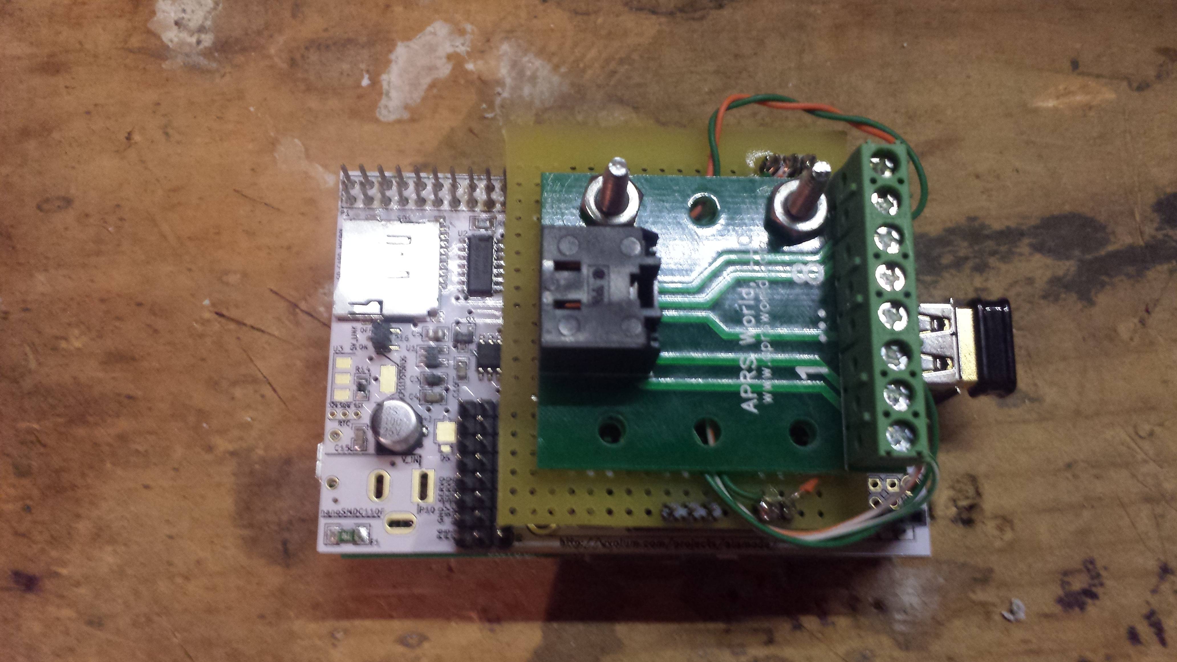
Top view
tpy4SfQ.jpg


Here you can see the 3 pins that are for the data (to the digital inputs) and the orange / green wires coming from the other side (orange is VIN, green is Gnd)
ECI0PbQ.jpg


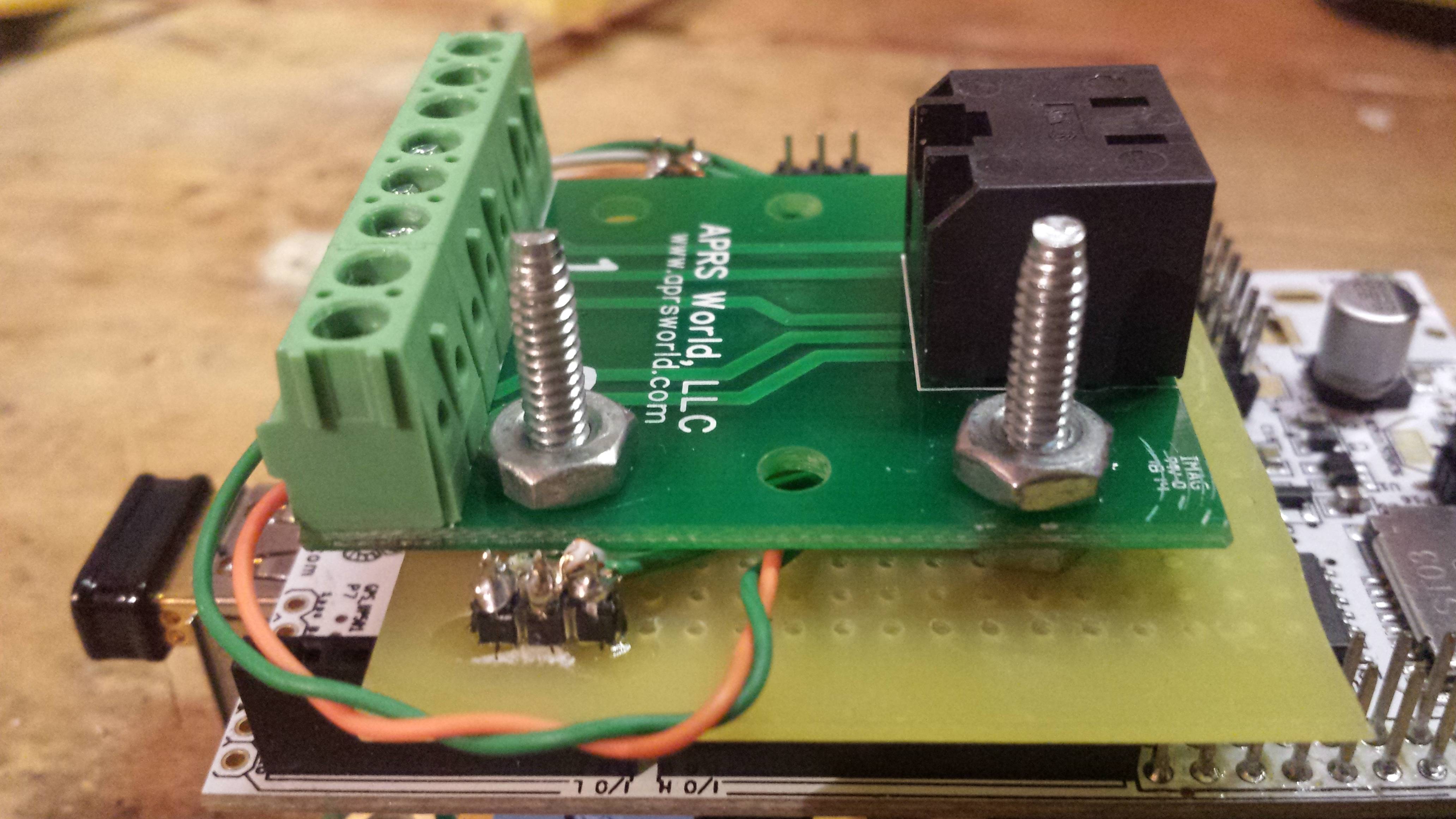
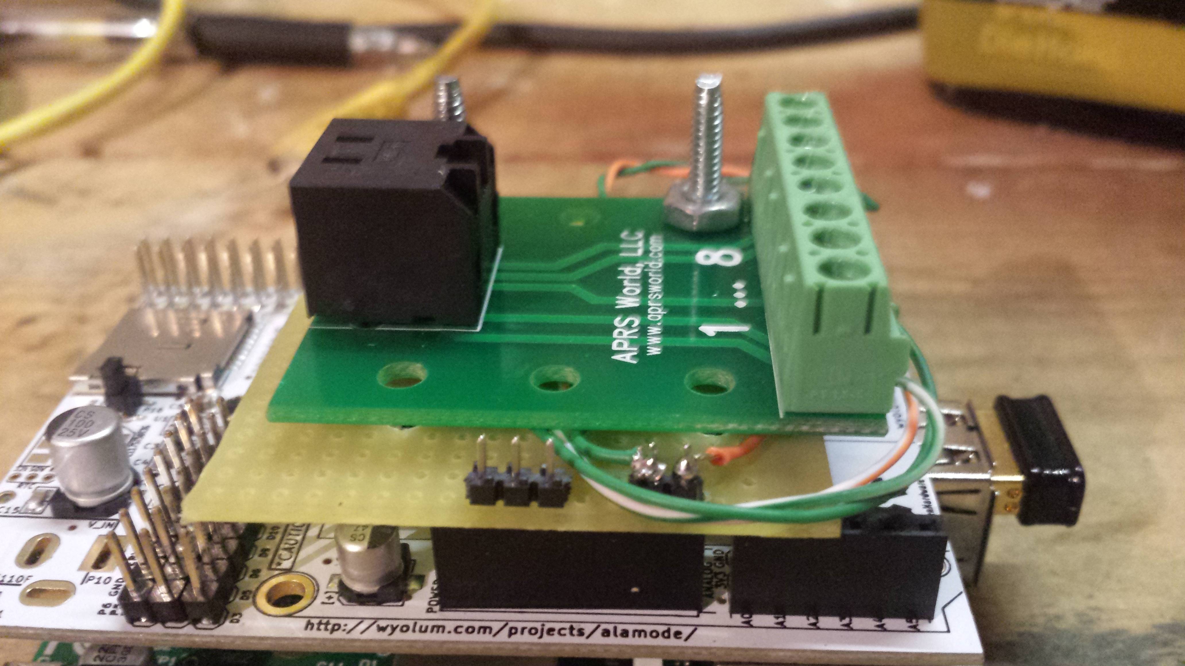
Here you get a pretty good view of how the perfboard sits on top of the alamode. The two pins to the right are Gnd (green) and VIN (orange). The 3 pins with nothing on them are just there to help hold everything together - they are not glued to the perfboard.
921ZT0j.jpg


The next photos will be of the other end of the box that will live in the kegerator.

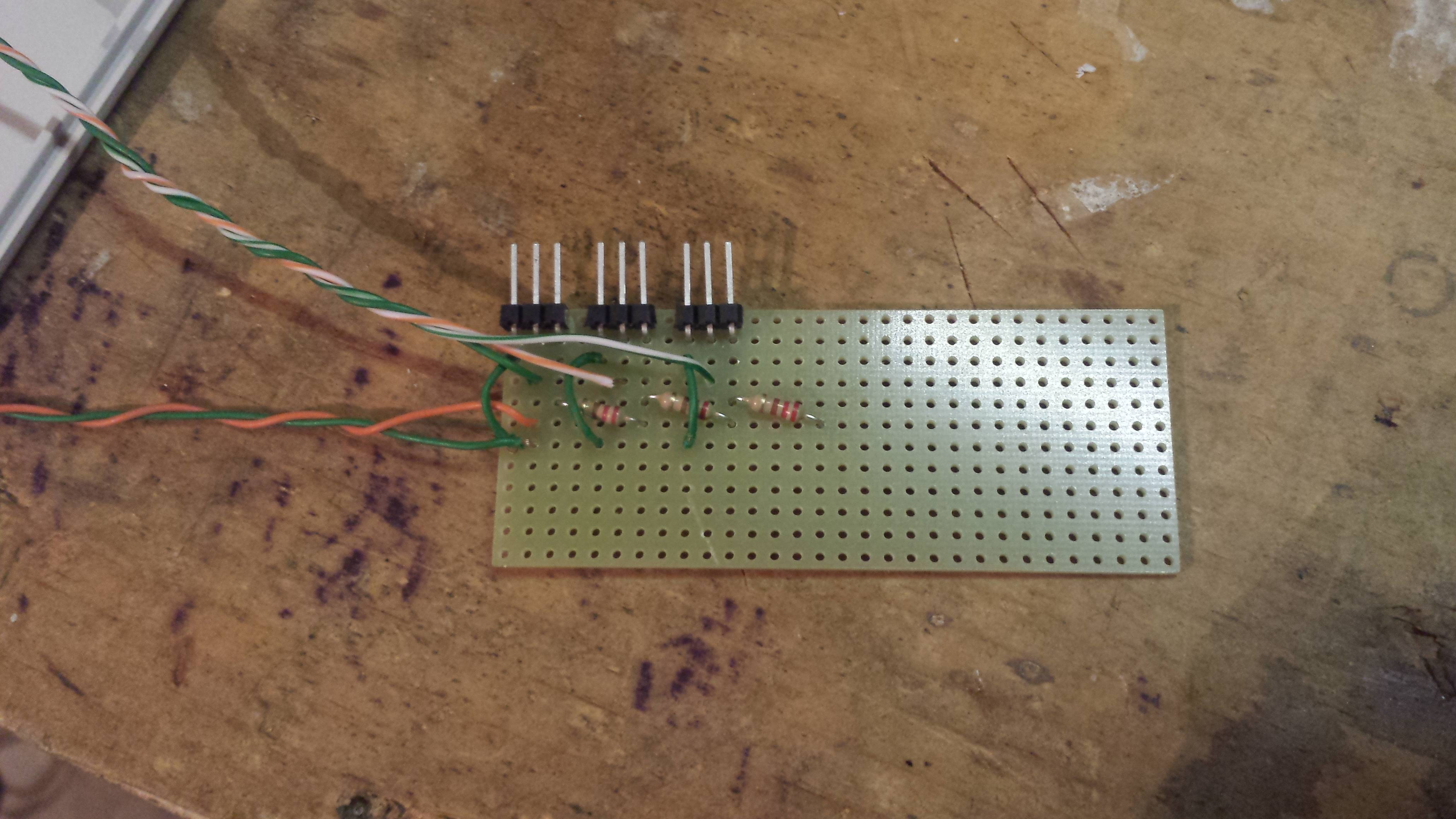
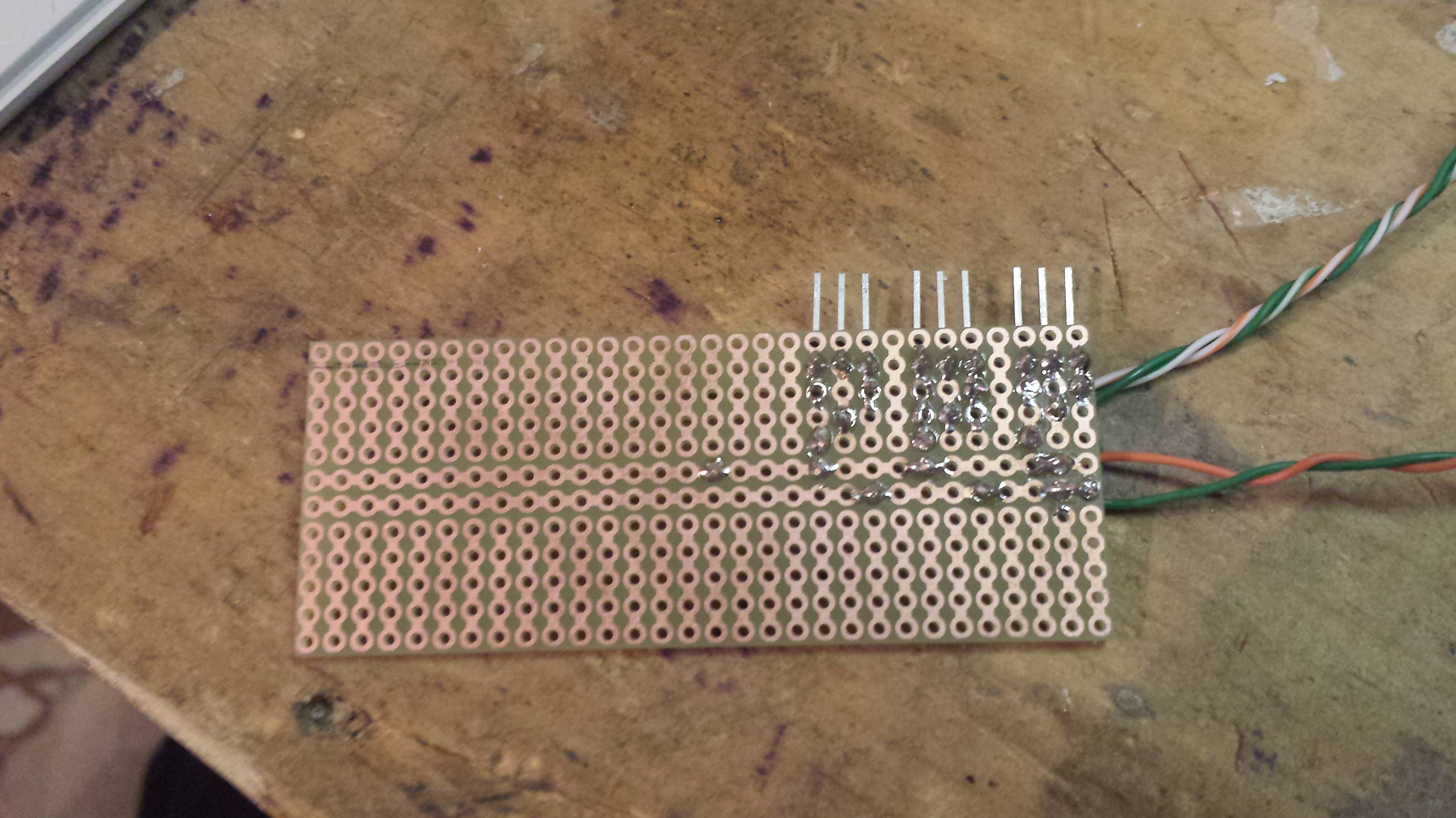
This is a photo of the breakout board I made to receive the pins from the flow meters. I have the resistors that day_trippr suggested. The green jumpers are for gnd. The colors of the wires in their bundles match the color codes of the previous segment.
GY07gFP.jpg


Here's the flip side - this board helped me lay things out and minimized the jumpers needed with wire. There's some excess solder from when I had jumpers going every which way, before I added the resistors and figured out a way to streamline it. The lowest horizontal trace is ground, the upper is VIN.
Lm3K3fc.jpg


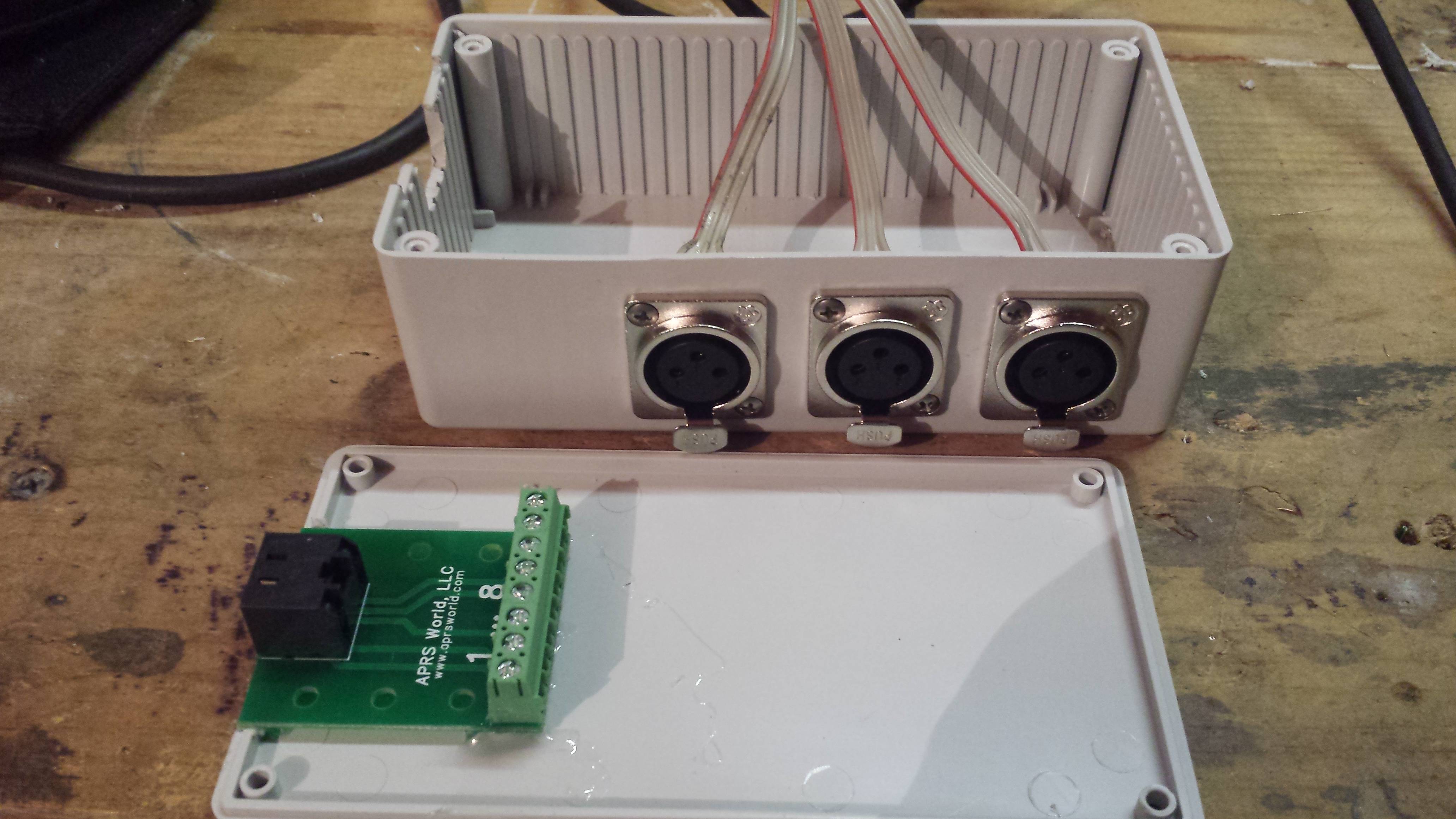
Here's what the project box will look like - I run the pins from the previous board to XLR connectors mounted to the outside, and will plug the flow meters into those. The RJ45 breakout board is glued to the lid.
uBWHBj6.jpg


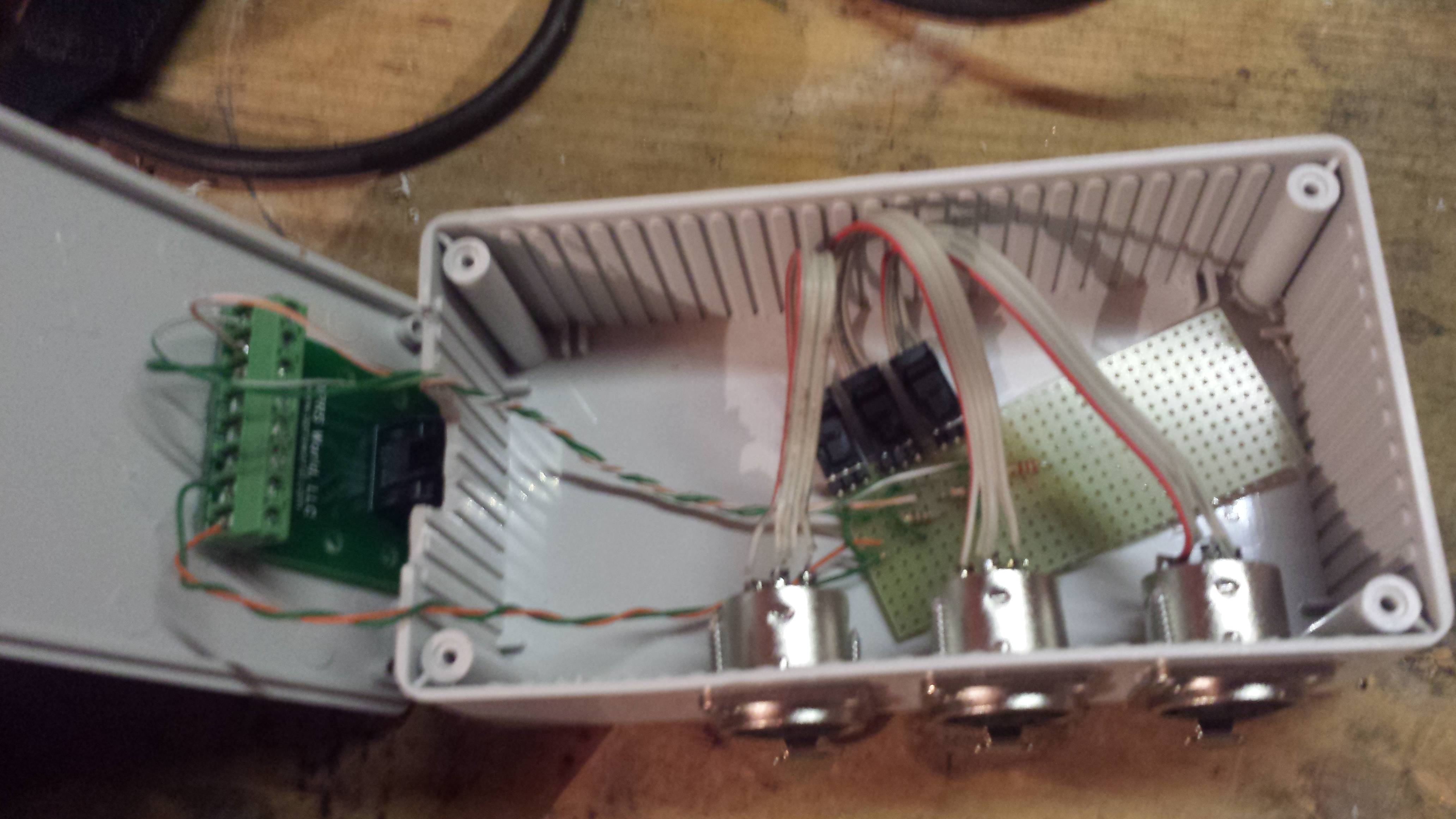
A picture of everything in the box - the lid just needs to be screwed on, once the box is screwed into the kegerator somewhere. I didn't secure the board - I figure it's not going to move once it's mounted.
PWSMBk2.jpg


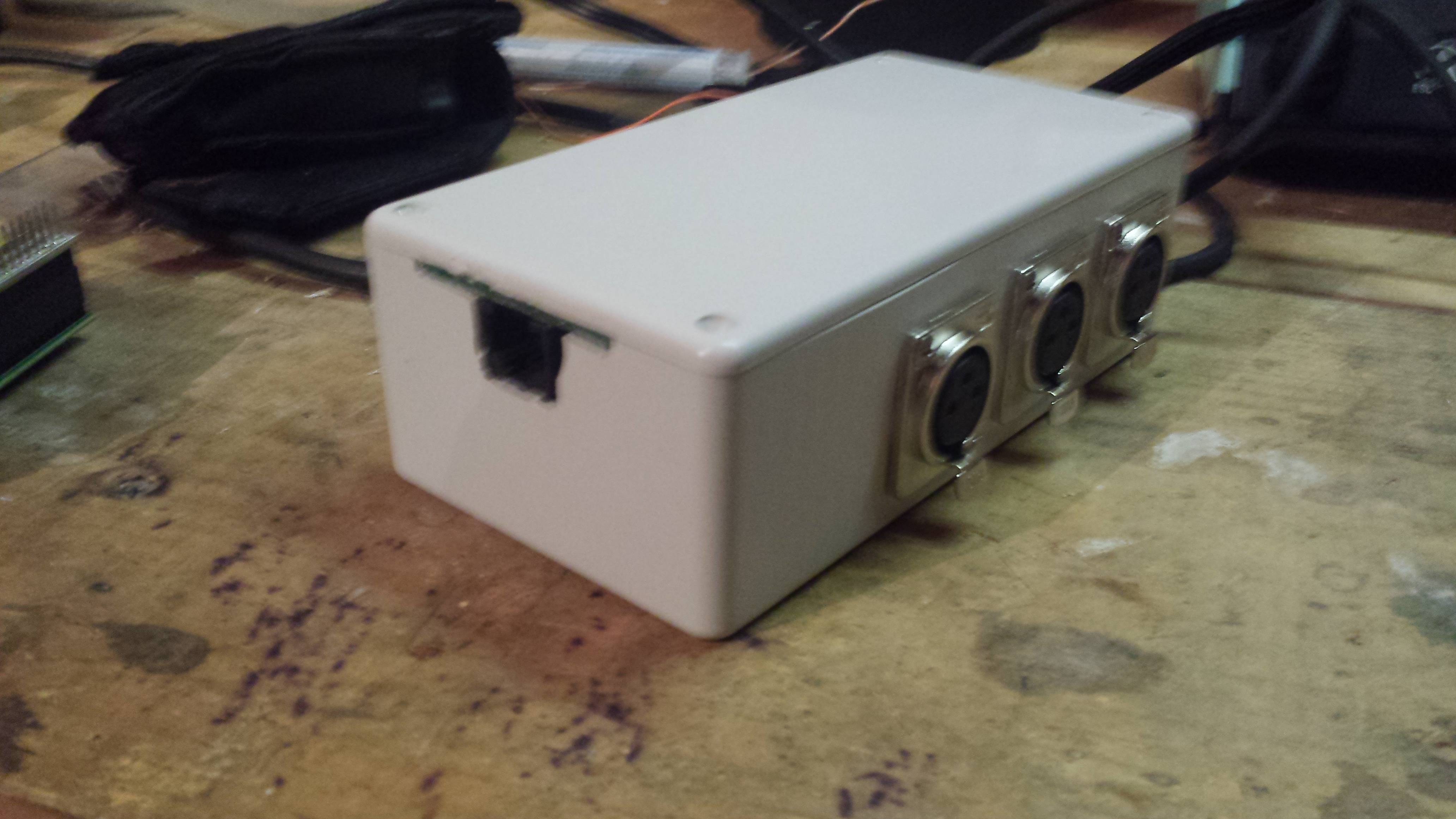
All buttoned up, ready to install into the kegerator and ready for an RJ45 cable to be plugged in and 3 flow meters!
zYeH6qr.jpg


I've never dealt with any circuitry of this nature, so hopefully I did OK. The next step is installing the flow meters, and then getting the programming figured out (which I'm saving for last out of pure terror).

Thanks all for your help, and hopefully this gives other's in my situation some ideas on how to do this!
-Kevin
 
Back
Top