Upside Down Keggles?

Homebrew Talk - Beer, Wine, Mead, & Cider Brewing Discussion Forum

Help Support Homebrew Talk - Beer, Wine, Mead, & Cider Brewing Discussion Forum:

This site may earn a commission from merchant affiliate links, including eBay, Amazon, and others.
Also, another question. Is there any benefit as far as flexibility goes using 60A vs 50A? Is it possible to run 2x 5500w elements on a 50A or do I need 60A for that? The breaker and spa panel are only a few $$ more for the 60A, but the plug and receptacle aren't cheap and are a lot more difficult to find than 50A it seems.

I've seen this guy's build and he uses 60A, but haven't seen many other examples:

https://www.homebrewtalk.com/f170/my-60-amp-kal-mutation-422931/

One 5500w element at 240v draws around 23a, less if the actual voltage is less, so you should be fine on a 50a circuit. Some will say you need to stay under 80% of the circuit rating, but my understanding is that only applies to continuous loads over 3 hours, and a pulsing SSR is not continuous.
 
Jeffmeh,

Perfect -- thanks. Unless anyone has a reason why I should keep the 60AMP stuff I'll return them tomorrow and switch to 50AMP.

One 5500w element at 240v draws around 23a, less if the actual voltage is less, so you should be fine on a 50a circuit. Some will say you need to stay under 80% of the circuit rating, but my understanding is that only applies to continuous loads over 3 hours, and a pulsing SSR is not continuous.
 
I think this drawing by PJ matches what I'm looking for perfectly. Anyone do something similar and have a parts list that you used? Will start piecing this together this week.

BCS-460-wiring-2-4-c.jpg
 
One 5500w element at 240v draws around 23a, less if the actual voltage is less, so you should be fine on a 50a circuit. Some will say you need to stay under 80% of the circuit rating, but my understanding is that only applies to continuous loads over 3 hours, and a pulsing SSR is not continuous.


Not correct about amperage draw, it would actually draw more amperage if the voltage is less. 5500 W is fixed. If volts go down amps go up, amps go down volts go up. You are right on continuous loads, those defined in the NEC as loads that are operated for 3 hours more. That just means for a 20 amp continuous circuit, it's max continuous load should be 16 amps. You should be fine operating this as a non continuous load, but no harm in upsizing.


Sent from my iPad using Home Brew
 
Thanks. To keep things simple I'm going to switch out the 60a spa panel and breaker and use 50a for both. Still using 6-3 with ground for wiring.

I assume PJ uses all 25a components for the control panel build listed above because the max draw per element is less than 25a? Even tho other builds use 40a SSRs, etc...

I meant no harm in upsizing the wire. Don't upsize the breaker. Match breaker to wire size.


Sent from my iPad using Home Brew
 
Not correct about amperage draw, it would actually draw more amperage if the voltage is less. 5500 W is fixed. If volts go down amps go up, amps go down volts go up. You are right on continuous loads, those defined in the NEC as loads that are operated for 3 hours more. That just means for a 20 amp continuous circuit, it's max continuous load should be 16 amps. You should be fine operating this as a non continuous load, but no harm in upsizing.


Sent from my iPad using Home Brew


That's not correct for our heating elements...

This may be true for devices that operate at a fixed level, but these are just big resistors, that's why people say that when you operate a 5500w element rated at 240v on 120v, you only get 1/4 the heat/watts output.

Search for the "electric-heat.xls" file that is floating around... It has a calculator to get the actual wattage from the elements rated specs when operated at different voltages, then you can calc the real amperage draw from the real watts and voltage being used.

**edit**
seems i cant upload the xls file, but it is here:

http://gnipsel.com/beer/software/calculators/electric-heat.xls

Hope that helps explain!!
 
Not correct about amperage draw, it would actually draw more amperage if the voltage is less. 5500 W is fixed. If volts go down amps go up, amps go down volts go up. You are right on continuous loads, those defined in the NEC as loads that are operated for 3 hours more. That just means for a 20 amp continuous circuit, it's max continuous load should be 16 amps. You should be fine operating this as a non continuous load, but no harm in upsizing.


Sent from my iPad using Home Brew

Check Ohm's Law with a constant resistance. I stand by my statement. :)
 
PJ drew that diagram up for me... I ended up radically "enhancing" that design when I decided to ru a BCS-462.

That said though, the design is solid. I used it to start with, and did just what I wanted. I wanted visual to know if a device was on BCS or Manual mode, and also wanted to know when things were also truly "on". This design achieves that.

As for parts, I got some off ebay, and some off of of ebrewsupply. I price shopped because I had time to do so... I knew the build wasn't going to happen fast.

If you're in a hurry, go ebrewsupply; good guy, a vendor here, and really the cheapest prices for everything for a single vendor.

-Kevin

I think this drawing by PJ matches what I'm looking for perfectly. Anyone do something similar and have a parts list that you used? Will start piecing this together this week.
 
PJ drew that diagram up for me... I ended up radically "enhancing" that design when I decided to ru a BCS-462.

That said though, the design is solid. I used it to start with, and did just what I wanted. I wanted visual to know if a device was on BCS or Manual mode, and also wanted to know when things were also truly "on". This design achieves that.

As for parts, I got some off ebay, and some off of of ebrewsupply. I price shopped because I had time to do so... I knew the build wasn't going to happen fast.

If you're in a hurry, go ebrewsupply; good guy, a vendor here, and really the cheapest prices for everything for a single vendor.

-Kevin
Kevin,

Awesome. Do you have a drawing of the version you used?

Also considering how I can use the same BCS to control fridges in another room...
 
Kevin,

Awesome. Do you have a drawing of the version you used?

Also considering how I can use the same BCS to control fridges in another room...

I attached it on here for you. If you want a full size image, shoot me your email.

In the diagram you'll notice I have terminal strips drawn in; that is so I had an exact number I knew I needed to purchase. For the LEDs I just jumpered from one light to the next for the neutral, so that is why there is non terminal strips drawn in on the neutral lines to the LEDs.

You'll also see I did not use PJ's Radio Shack backup power source, and I am also driving my things in manual mode, not off of the +5vdc on the BCS but rather an external 5vdc converter (by Meanwell). This gives me power backup if the BCS ever goes down, in an industrial converter with DIN mounting.

That brings up one other thing- I used all DIN mount components except for SSR's-- they really made install go very smoothly. I also bought a really nice spring loaded DIN clip which I added to the BCS casing so it could be mounted/removed very easily too via the DIN rail. It was $8.00 shipped to me, and definitely worth it. I got it from http://www.winford.com and the part# is DINM15V2-RC

IF you have other questions, fire away.

image5-64148.jpg
 
Oh, I forgot to mention... For remote fridges/ferm chambers I use CAT5 cable to carry the BCS signal wires and temp wires from the Control Panel to the external source, then run them into junction boxes with SSR's to control my KegErator or ferm chamber, etc. that is why you see wires out of the BCS not terminated to anything for the KegErator and ferm chambers.

Also, ignore the outputs on the BCS I used in the drawing... It was done merely for the ease of the drawing, and do not reflect the actual outputs I use (important to note because you only get PID control on outs 0-5, although with firmware 4.0 that feature will expand and be available to outs 0-7).

PS. This whole drawing was done using MS Paint!
 
Very cool! Thank you! I tried finding your build thread but didn't see one... Did you document your build somewhere?

Will read through your diagram and see if I have any questions. One right off the bat -- is the 6 amp breaker a double pole?

Do you have pictures of your control panel?

You're welcome; unfortunately I do not have a build thread... I built an entire room, rig, KegErator, etc and took some pics, but I am bad about remembering to take pics all along, and then writing it up when I am done!

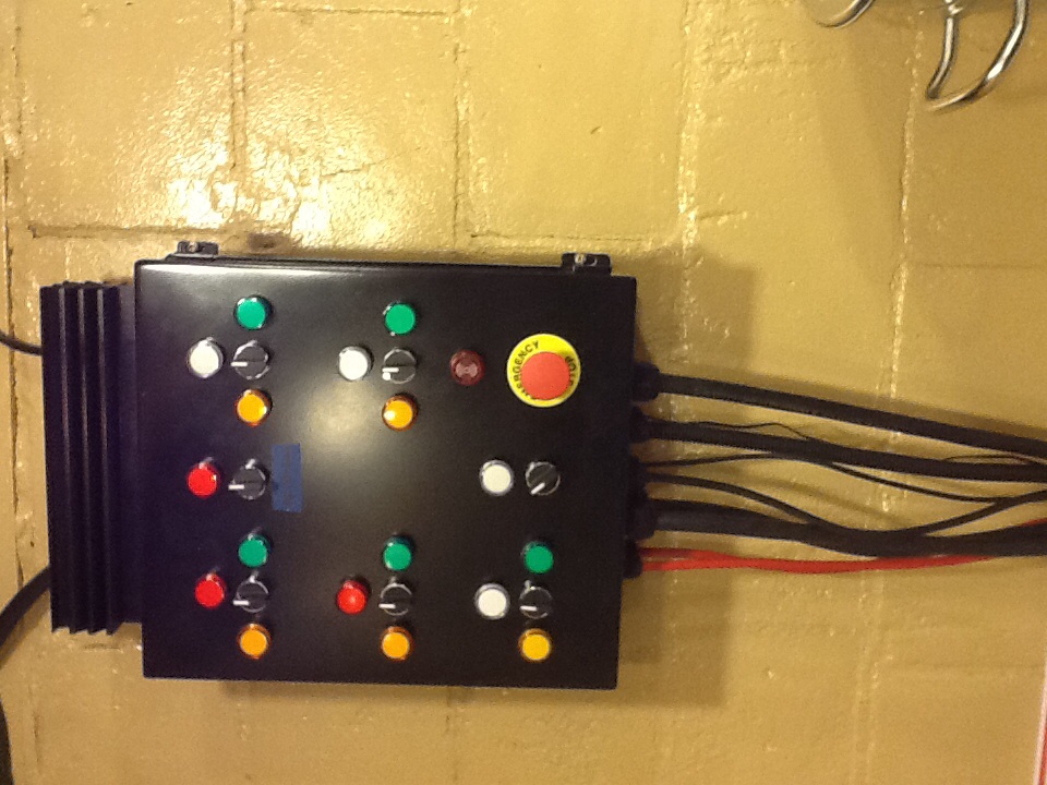
Here are a few pics of the panel.

In regards to the 6a breakers, they are single pole.

image4-63869.jpg

image-63870.jpg

image1-63871.jpg
 
There are no "sub-panels" per se for the ferm chambers and KegErator. The CAT5 cable is run into a dual gang electric box, hooked up to an SSR, the outputs for the SSR are then wired into a receptacle. Plug the unit into receptacle: voila!

For the temp probes, I pull two wires for the temp probes and do not insert them into the gang box, but rather connect them to a temp probe and insert the probe where appropriate.
 
Got it.

Looking at enclosures now. Would a 16x16x8 enclosure be good enough or would people recommend going a little larger (IE: 20x20x8) to get more room?
 
Another Q -- you have 5 SSRs in your setup. 2 go to the elements, 2 go to the pumps, and 1 goes to the alarm, is that correct?

So basically, the BCS turns on / off the pumps based on what is set in the unit, and also turns on / off the alarm for various reasons?

There are no "sub-panels" per se for the ferm chambers and KegErator. The CAT5 cable is run into a dual gang electric box, hooked up to an SSR, the outputs for the SSR are then wired into a receptacle. Plug the unit into receptacle: voila!

For the temp probes, I pull two wires for the temp probes and do not insert them into the gang box, but rather connect them to a temp probe and insert the probe where appropriate.
 
Another Q -- you have 5 SSRs in your setup. 2 go to the elements, 2 go to the pumps, and 1 goes to the alarm, is that correct?

So basically, the BCS turns on / off the pumps based on what is set in the unit, and also turns on / off the alarm for various reasons?

In the drawing there are 5 yes- 2 for elements, 2 for pumps, and 1 for the alarm. In the pic of the panel there are actually 6 SSR's, as I added an extra in case I wanted to add a mixer.

But yes, the BCS turns on/off everything based on my process programs. However, there are the switches involved, so when the switch is turned to "manual" mode the SSR's are still being used to activate the device, but the SSR input is being driven by the Meanwell 5DVC converter I referenced in an earlier post.

As far as CP size... Go bigger if you can afford it. The CP above is 16 x 18 IIRC and it is TIGHT! It might look okay, but for working in the panel, the extra space would be very nice to have.

:mug:
 
ImageUploadedByHome Brew1415238649.039566.jpgImageUploadedByHome Brew1415238669.574538.jpgImageUploadedByHome Brew1415238682.677312.jpgImageUploadedByHome Brew1415238692.427832.jpgImageUploadedByHome Brew1415238710.959729.jpgImageUploadedByHome Brew1415238723.294776.jpgImageUploadedByHome Brew1415238737.909627.jpgImageUploadedByHome Brew1415238746.779188.jpg

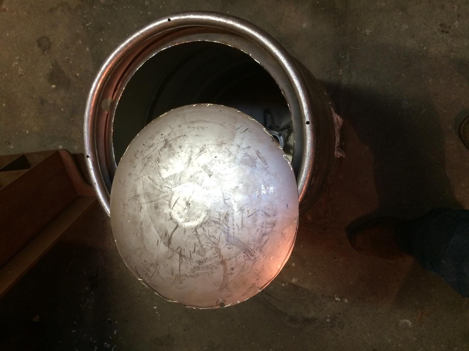
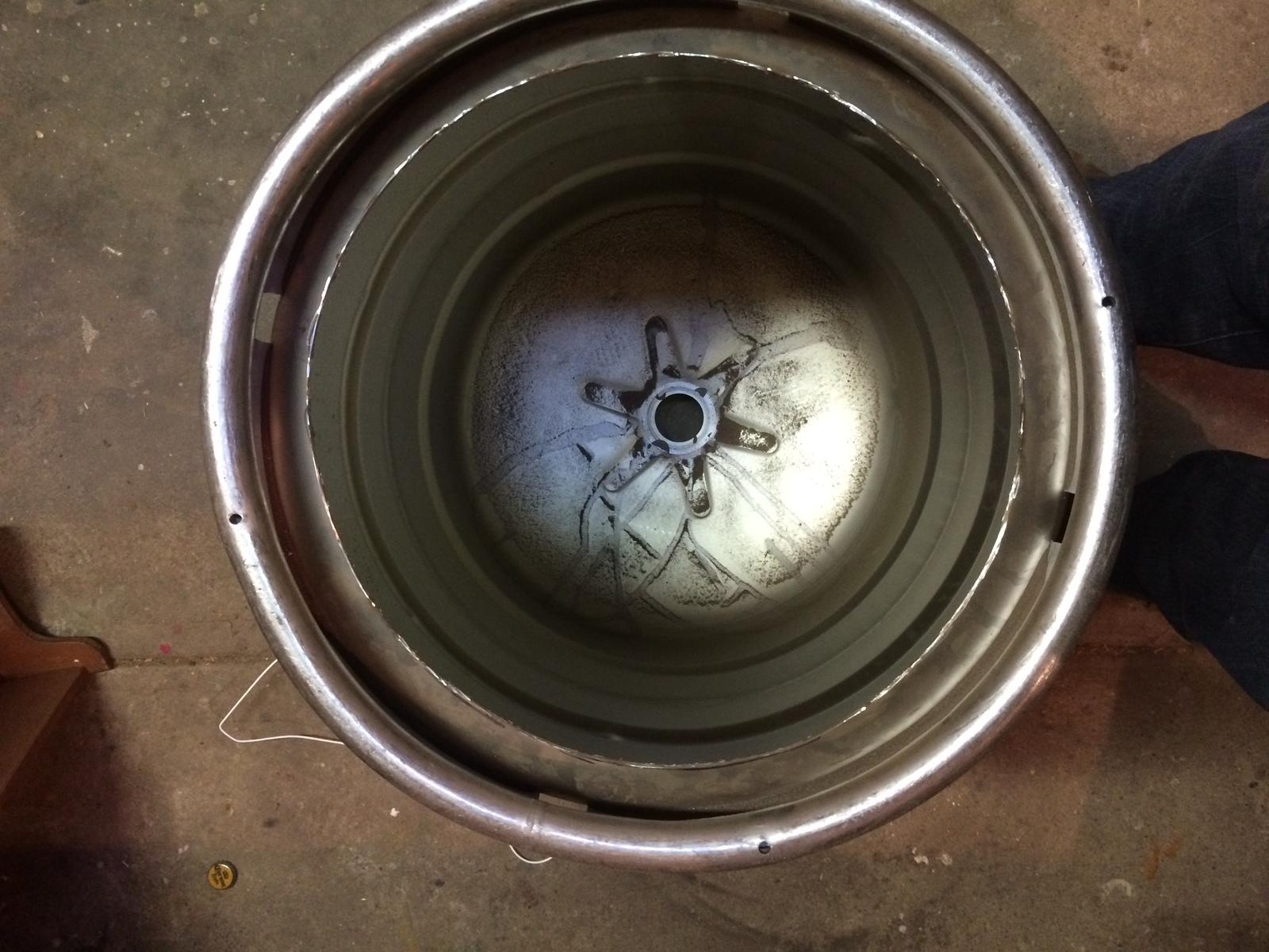
Here's a little progress on my build! First Keggle getting trimmed up!
 
ImageUploadedByHome Brew1415238820.238947.jpgImageUploadedByHome Brew1415238831.188476.jpgImageUploadedByHome Brew1415238847.904837.jpgImageUploadedByHome Brew1415238861.454731.jpgImageUploadedByHome Brew1415238872.871464.jpg

Tops cut!! Still need to dull the edges. My old Boil Kettle lid fits perfect!!
Still hunting for a third keg.
 
Thanks. I'll get a bigger one.

Will post up my BOM later today... Trying to piece together the kettle parts first and then will go back to the control panel... A ton of pieces.

Came across this today for a locking 50A receptacle; the price seems right and it looks like i can take off the black housing at the end, would this work to install into the control panel?

http://www.ebay.com/itm/50-amp-125v...Parts_Accessories&hash=item5b0074363e&vxp=mtr
 
Here's my build list for the kettles and misc. Anything I'm missing? I'm thinking I'll do a sight glass on the BK and HLT, but with the bottom drain / pipes and ball valve where would I mount it?

Also, based this primarily on Kal's part list but made modifications based on some of the parts BrewHardware has -- bulkheads, etc.

HLT:

attachment.php


BK:

attachment.php


MLT:

attachment.php


Hoses:

attachment.php


Wort Chiller:

attachment.php


Pumps:

attachment.php


HLT.jpg


BK.jpg


MLT.jpg


Hoses.jpg


Pumps.jpg


WortChiller.jpg
 
I'm sure others will disagree with me, but I don't like my sight glass, it's a pain to clean, not all that accurate (my fault admittedly), and in my opinion not much better than eye balling things...(half of the 15.5 gal keg is marked, as is thirds with the rings)

I'm in the process of plugging my sight glass and I'll put etchings on the inside of my keggles, not sure how much better that is, but I'm close enough to hitting figures for what I want.
 
I'm in the process of plugging my sight glass and I'll put etchings on the inside of my keggles, not sure how much better that is, but I'm close enough to hitting figures for what I want.


Brew Your Own magazine had an article a couple months back that showed how to do your own etching at home with household ingredients. I haven't tried it yet but it appeared to be pretty effective.
 
Alright I'm $1,200 poorer. I'm all in now. :) Keg parts on the way, will order pieces for the control panel this week.

Guess this will become my build thread as well.
 
Cool, thanks!

Did you guys build some type of jig to cut out the bottom or did you more freestyle it?

Also, what did you build your frame out of?


I used a sharp, a ruler, and a dremel with the cutting wheels. unless you get the separate pack of cutting wheels it will take a while, make sure to score your lines by going over it a few times to get a groove and don't try to cut right into the keg, that will run down your wheels really fast... i learned that the hard way. all told it took about 45 minutes and i got really nice cuts.

IMG_7405.jpg


IMG_7406.jpg
 
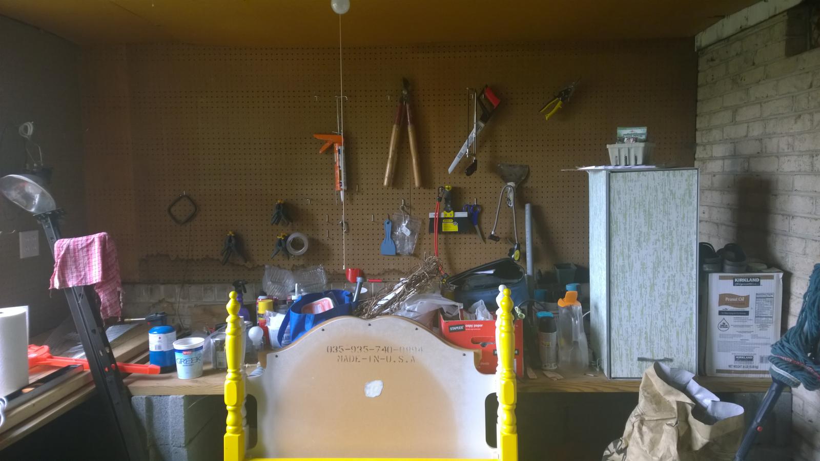
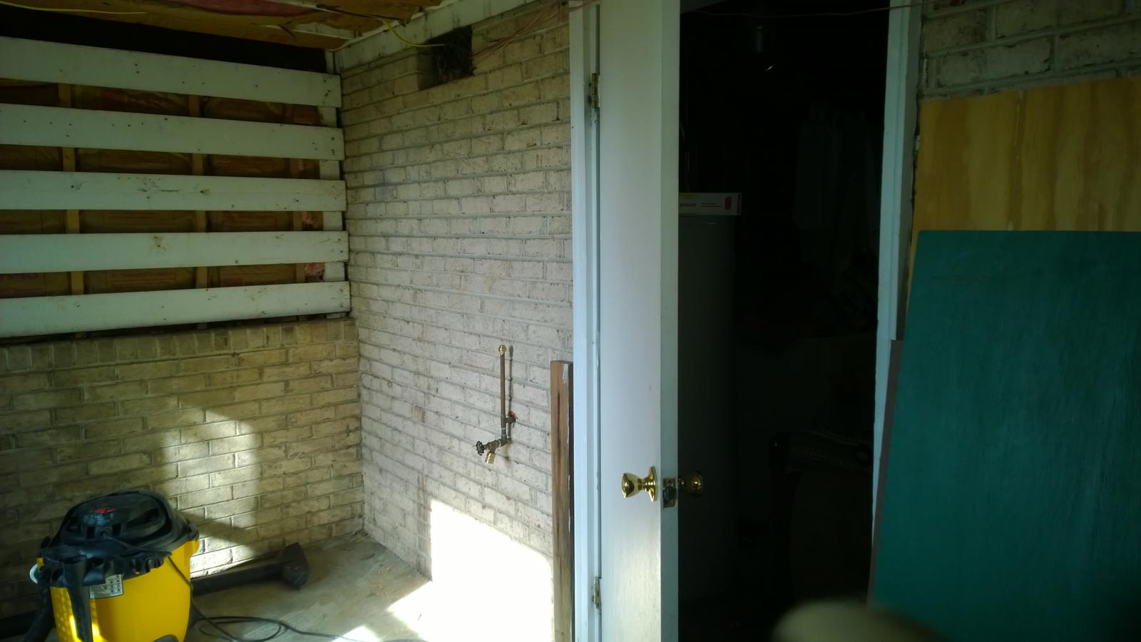
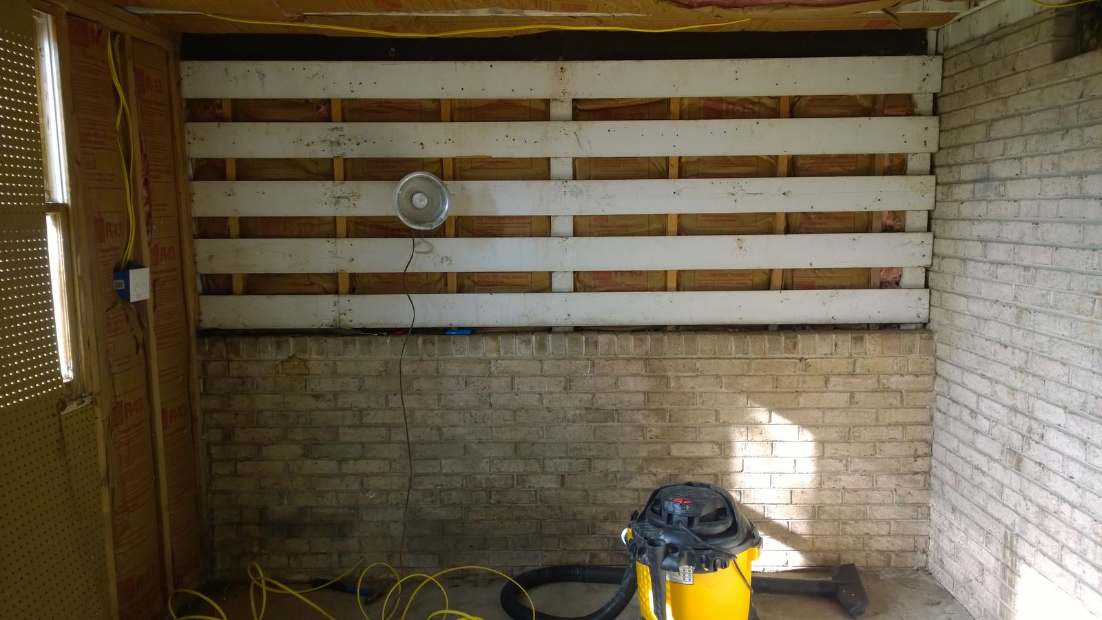
Alright so I'm cleaning out what will be my brewery today. This room is currently a "potting shed" that is directly attached to the house. Plumbing / electric are on the other side of the wall on the right and in the basement. On the left are some old windows. Room is roughly 10' wide so I should have enough space.

attachment.php


I'll be cleaning this all out today and may start running electric / plumbing through the wall if time permits.

I'm considering building two fermenters right underneath of the bench -- an ale fermenter and a lager fermenter, similar to this build:

https://www.homebrewtalk.com/f258/my-mini-fridge-fermentation-chamber-build-256068/

Basically two fridges opposite each other and my pumps in the middle.

WP_20141103_12_58_17_Pro.jpg
 
Subbed. Love the idea of the etching. I was just looking to buy sight glasses but I think I will go with etching instead.
 
Got everything cleaned out yesterday. Ran a new 20 amp circuit for outlets in the room. Will run another for ceiling lights and a vent fan.

At this point I'm planning on using track lighting, anyone have any other suggestions?

Also, any recommendations for a ceiling? Will likely use plywood at this point.

Looking at using some bathroom faux tile sheets for the backslash. Comes in 4x8 sheets and it's cheap.

WP_20141109_09_55_26_Pro.jpg


WP_20141109_09_55_17_Pro.jpg
 
Back
Top