Two panel set up. Separate high voltage panel

Homebrew Talk - Beer, Wine, Mead, & Cider Brewing Discussion Forum

Help Support Homebrew Talk - Beer, Wine, Mead, & Cider Brewing Discussion Forum:

This site may earn a commission from merchant affiliate links, including eBay, Amazon, and others.

cank

Supporting Member
HBT Supporter
Joined
Nov 17, 2012
Messages
523
Reaction score
36
Location
Jonesboro
Two panel set up
Separate high voltage panel.
I am working on a new setup and trying to come up with a drawing. I want to have 4 three way selector switches that switch from manual to auto(raspberry pi) and off for the elements and two pumps.
I also need to figure out an automatic valve with a float switch for filling the hlt in the morning.

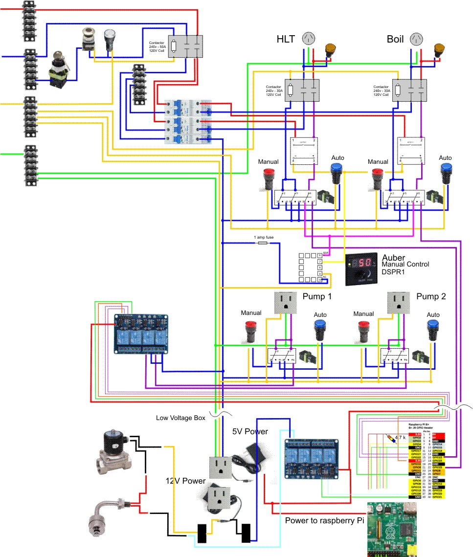
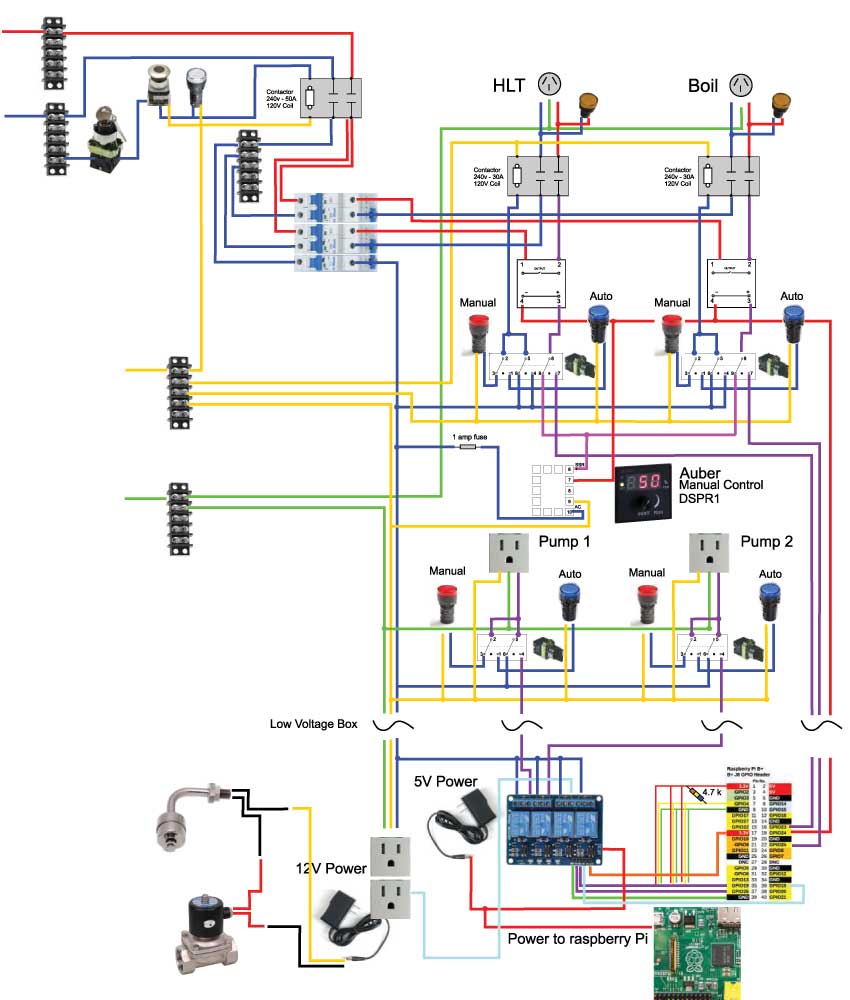
Right now I'm working on the high voltage box. I have this drawing that I came up with but wanted the experts to let me know where I've gone wrong, if at all. It might look similar to PJ's but don't be fooled, I designed this mess and don't want anybody else to run with this until the experts chime in.

I have a keyed switch then an e-stop going to a 50 amp contactor which leads to one 15 amp and two 25 amp breakers. The 15 amp breaker runs the indicator lights, contactors, two pumps and runs to the low voltage box. In the high voltage box I will have an Auber dial boil control that is hooked to each of the ssr's in the manual mode. In the "auto mode", the raspberry pi will drive the ssr's. Similarly, the pumps will turn "on" in the manual mode and be controlled with a Sain-smart 4 channel relay and the raspberry pi.

Other components like the float switch, valves and temp probes will all be hooked up to the low voltage box and any connections to the high voltage box will be maid with a xlr plug.

My thoughts with separating the boxes is so that if anything happens to the pi, I can still run it with just the high voltage box and also to just separate those components.
TwoBox-Wiring.jpg
 
Starting on the panel....
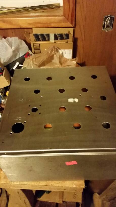
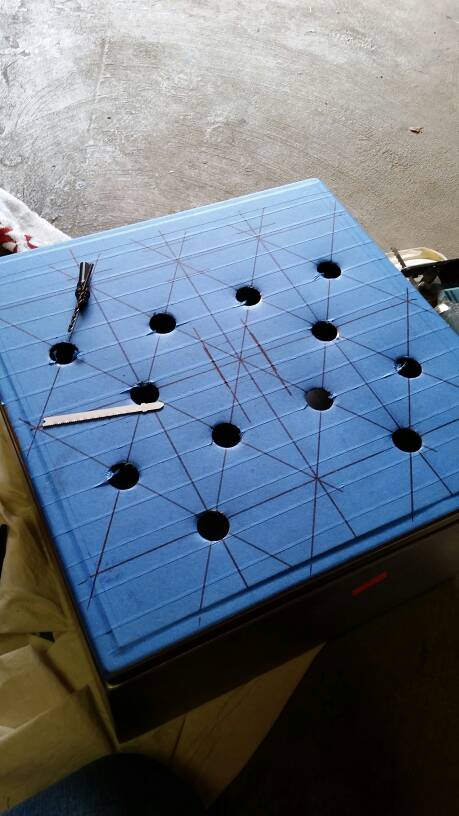
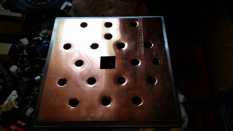
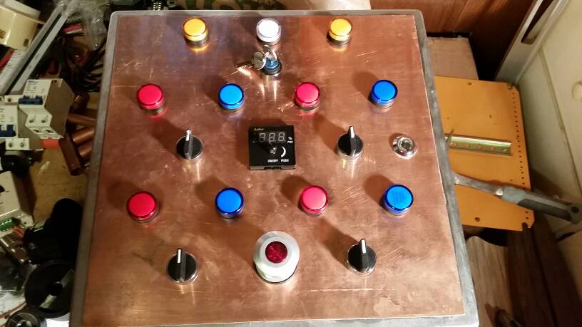
I got a stainless panel from ebay that had holes in it already. I thought I might get away with using them but I couldn't get all the lights in. I put a piece of copper on top with silicone and started laying out the panel.

1411872856748.jpg


1411872930820.jpg


1411873125743.jpg
 
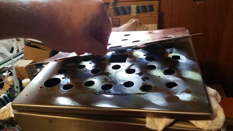
Ok. So I lied. I tried to use job weld and after I punched to holes, the copper started coming off. Last pic just shows how I'm using lights to help clamp the copper down(some of those will be switches).

1411873565563.jpg


1411873581883.jpg


1411873597271.jpg


1411873617578.jpg
 
Well I looked through your design. It all looks well to me. You specifically asked about 'safe' from another thread. So you have the right breakers, your contactors have the right ratings. You fused your controller. Your estop is done correctly. Don't know what to say. It looks good. As long as all your wires are the correct size all should be well.
 
Looks nice! If I was going to make any changes it would to add a fuse or diode to the wires coming from the pi into the high voltage box. Just in case a stray wire hit one of them and made the pi melt. Any chance of a finalized BOM?

As a pi owner I'd love to see the whole process.
 
This brings me to a question.
Neutral doesn't care where it comes from does it? I originally had a seperate neutral for the lighted e-stop and the Auber boil control but decided to nix it.
 
depends if your fuse box has a 4 wire or 3 wire set up, isolated ground to earth I mean.

and that purely has to do with lightning and jumping across and shorting out not your design, for the box that gets unplugged after every use, common and neutral and ground can come from the same place
 
depends if your fuse box has a 4 wire or 3 wire set up, isolated ground to earth I mean.

and that purely has to do with lightning and jumping across and shorting out not your design, for the box that gets unplugged after every use, common and neutral and ground can come from the same place
And it also depends on if you want to meet code.... bonding the neutral and ground in the panel is a no no for safety reasons... since the OP is going all out on safety it doesn't make sense to break code this way to me...the only place the N and Ground can be bonded is in the main electrical breaker panel.
I would believe if something ever did happen its a sure excused for the insurance company to not pat the claim...
 
Yes, my line-in neutral and ground are separate. I was referring to inside the panel where I took the neutral for the boil control from the neutral at the e-stop.

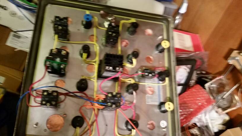
In the photo in post 11, bottom left center is the e-stop. Center left is the boil control. Neutral is Yellow
Neutral for e-stop comes straight from the terminal block. The other neutral from the terminal block goes to all the led lights.
 
I'm not sure if I understand your question correctly, but the neutral doesn't care where it comes from at all. Technically it is all coming from your neutral bus at the panel, so as long as you don't have any separately derived systems (transformers) and your neutrals have a path back to the panel then you are good.

One thing to consider is loading on the lugs. If you have a small lug carrying a lot of current then that can become a hot spot. So assuming that your elements are 240v, my being lazy and not looking back at your original design, you shouldn't have anything that would cause considerable loading on the neutral.
 
I'm not sure if I understand your question correctly, but the neutral doesn't care where it comes from at all. Technically it is all coming from your neutral bus at the panel, so as long as you don't have any separately derived systems (transformers) and your neutrals have a path back to the panel then you are good.

Finishing up on high voltage panel and starting to look at my low voltage set up.

So Facinerous, if I am understanding you correctly, I will have 2 separate transformers, 5v and 12v, to power the pi, sain smart relay, and a 12v valve. Any neutral coming off these should not be connected to a 120v neutral bus and in fact should be seperate from each other?

One more question:
The positive side of my ssr will be switched between the pi and the Auber boil control, can the ssr neutral just be connected to the Auber Boil Control?

In my drawing I had it coming back to the pi also.

Thanks to Doug for getting a PH probe set up for the pi too.
 
For the low voltage side, will you be rectifying the DC yourself? (i.e. transformer, diode bridge and regulator or something similar) or just using a ready-made rectifier?

Essentially, the 120v supply leads going to your rectifiers will get a hot and a neutral but that will be the last of the use of either of those lines on the low voltage side. From there, it's all DC so you have +12v, +5v and Ground. You'll run the +5v and ground to the rpi. I've not used a sainsmart board yet but if they work how I think they work, you'll run a 12v line to the Common port of the sainsmart relay, a line from the rpi GPIO to the coil+ side of the relay and ground to the coil- side. Then, a wire from the normally-open (NO) port on the relay to the +12v side of your pump/valve/load and then a ground to the other side. Essentially, when the rpi GPIO provides a +5v signal, the coil on the relay will energize and close the NO-Common connection which will then provide +12v to the load of choice.
(That is all of course assuming the programming is setup for a GPIO "high" condition to activate the loads and that the relays can be tripped with 3.3v)

if the relays won't trip at 3.3v, we'll need to add a transister in there to switch a 5v control signal to the relays, not a big deal.

If you haven't picked out your power rectification yet, I like to rectify to 20v or so (old laptop power supplies work great!) and then use adjustable switching regulators to get my desired voltage. I run my rpis this way and when I tune it to 5.10V across the test points, I get rock solid stable performance even overclocked at 1ghz. I can help you more with that if you go down that path.

-Josh

Edit. The adjustable regulators I use are the LM2596. If you you search for that on Amazon there are an assortment of options. I just use the ones without the LCD because I can usually pick them up for less than $1 a piece. They are good for about 3A.
 
Just going through what JayElDubya said he sounds right. Its hard to build in my head without the parts in front of me.

As far as the neutral part goes. It sounds like you already know what is going on with that stuff. When I refer to neutral I am referring to an AC voltage, where a DC system does not have a neutral... Technically.

I only brought that up the separately derived system thing because I was not sure what you are using to bring your rectify your AC voltage for use with your control devices. If you are simply going to use a 120V plug and wall wort then don't worry about it. Also if you use JayElDubya's idea (which I personally like) using a laptop power supply you still don't need to worry.

Still you are right. Once your voltage is regulated down to 5v or 12v then all of those wire should only go to their respective voltage. I am going to assume you are going to use two separate wall worts for your project, so please also note that your 5v system needs to be separated from your 12v system.

I looked back at your original drawing and it all makes sense there.
 
Correct. You will need to keep the +12v bus isolated from the +5v. However, the grounds (- lines) can (and should) be bonded together.
 
I agree JayElDubya that you 'can' bond the two together, and sometimes this is necessary. As when you have multiple digital devices using various voltages and need signal reference point. I don't think the op would need to have to much concern for his system, but here are two threads which supply reasons not to bond your negative between different sources.

I don't mean to be argumentative, please just take it as food for thought.

http://www.edaboard.com/thread49359.html

http://forum.arduino.cc/index.php?topic=13452.0

As it would be post #4 in both links are good to know when working with low power signal circuits and higher current loads.
 
I'm planning out a controller, to this point I hadn't even considered a seperate box for LV and HV. Thank you for posting this thread. My LV was going to be arduino based with what seems like an endlessly expanding set of sensors and... junk, seperating the two sounds like a good idea at the moment.

I'm looking forward to watching your progress.
 
I agree JayElDubya that you 'can' bond the two together, and sometimes this is necessary. As when you have multiple digital devices using various voltages and need signal reference point. I don't think the op would need to have to much concern for his system, but here are two threads which supply reasons not to bond your negative between different sources.

I don't mean to be argumentative, please just take it as food for thought.

http://www.edaboard.com/thread49359.html

http://forum.arduino.cc/index.php?topic=13452.0

As it would be post #4 in both links are good to know when working with low power signal circuits and higher current loads.

Please, I am on a never ending quest for personal knowledge-expansion and I welcome respectful counter points. I think both of your links basically make my point though. I don't think you should tie the AC and DC grounds together. I'm saying the DC buses should have a common 0vdc reference though. i.e. the +5vdc and +12vdc lines should have a common return line or point where the "negatives" are tied together. Otherwise, your +12 and +5 are arbitrary to each other and much care must be taken to avoid ground loops. I think both of those links support my thinking. I do not however recommend connecting that 0vdc reference to the AC neutral line. Connecting that 0vdc reference to chassis ground *should* be okay, but not necessarily required, and the merits or hesitations of that I'd be interested in discussing.

(All of this is assuming your grounds are properly bonded back to your building ground system and that your AC neutral lines are bonded to ground in only one location...your building's primary electrical panel per NEC and NFPA-70 in the U.S.)

-Josh
 
DC voltage will be supplied by two wallworts. I have also decided to place another Sain-smart to control the pumps inside the HV panel so there will only be 120v coming in to the outlets and the rest will be DC.

TwoBox-Wiring2.jpg
 
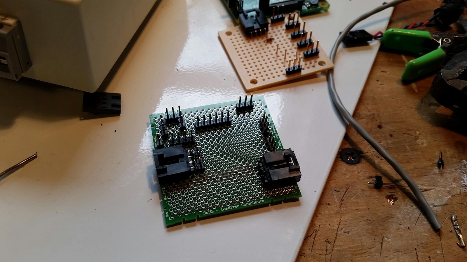
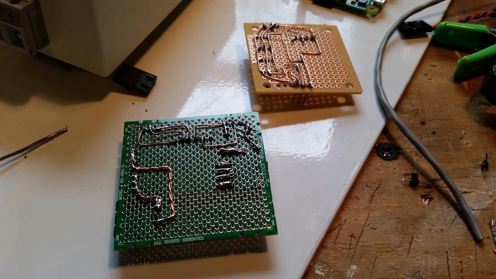
Here are the first parts of the LV box coming together. The Tan board will be for all my temp sensors. The green board will have connections for both Sain-smart relays, Main Element SSRs, PH probe, 5v and 12V power.
Still trying to figure out all the wiring.
This gets confusing :drunk:

20141231_094850_resized.jpg


20141231_094900_resized.jpg


20141231_191045_resized.jpg
 
What kind of connectors and cables are you thinking of using to connect the HV box to the LV box? Are you putting your relays in your LV box?
 
What kind of connectors and cables are you thinking of using to connect the HV box to the LV box? Are you putting your relays in your LV box?

Relays that switch HV are in the HV box. I'm using a Mini XLR 6-Pin connector for the sainsmart in the HV panel that controles the pumps and a 3-pin Mini XLR to send the signal from the pi to the ssr's.

A L5-15 connects 120 from HV to LV panel.

I'll use these to connect temp probes:
XS8-3Pin Quick Pull/push Steel Ball Lock Aviation Connector Aviation Plug
 
How's this coming along?

Thanks to this post I decided to go with separate HV and LV boxes too. I just finished up my HV last night. Now I will be able to fiddle with the low voltage controller part and not have to worry about messing with this HV half of the project. I expect that my LV (arduino) side will be continuously upgrading with new sensors and features so this separation is very convenient.
 
Getting closer. I had to order a few more connections. I am getting a 6 pin mini xlr to connect the low voltage signal to the pump relays in the HV panel and I might have to redo the wiring for that too, to make it cleaner. I originally had two separate xlr plugs and not enough wire colors. I should be able to clean that up and make things easier to follow. I've tested for continuity between panels and made sure switches work correctly and I didn't find any shorts to ground.

Oh, I've also added some extension ports for the Pi in the LV box in case I need to have my wifi adapter on the outside of the box for good signal, a HDMI port, and a network port just in case. I put in a 120v receptacle to plug an ipad charger or possibly a monitor in as well if needed.
 
Had a chance to try and set things up yesterday and today but I had some trouble...

I have one of these Teledyne Dual SSRs and I can't get the Raspberry pi side of the Low Voltage panel to activate the SSRs.

When I put it in Manual mode and use the Auber DSPR1, the elements work fine.

Would it have to do with ONLY the neutral from the DSRP1 being hooked to the SSR and I am using a NC block to switch the Positive side of the SSR input? Therefore, I don't have a neutral going back to the PI or the LV panel and the DSRP1 runs about 10Vdc while the pi is sending 3.3Vdc.
 
3.3V sux! You might be able to get away with modifying the ground (raising the Pi voltage) by adding a diode or 2 to it's GND , that should give you full almost 5v

BE CAREFUL when using virtual gnd's though, can get hairy real fast...

MIGHT have to change dc power supply for Pi if you're only using 6v to 9v or 12v so onboard regulator actually regulates.


I'll leave it to a guru on here that could draw better than me to give you a wiring diagram
 
Looking at the datasheet for that relay, the control voltage is 4-30 volts so If you're trying to drive it just off of the gpio pin 3.3v output, it probably won't work. When I get back to my laptop I can look at your circuit a little closer and make some recommendations. Basically you'll need to use a BJT transistor or logic-level FET as a level shifter to use your 5v or 12v source to trip the relay. It's generally a good idea to do this anyway to limit the current that the pi needs to handle.
 
Ahh, okay. I see you are indeed trying to drive those relays directly according to your drawing. You'll need to level shift it up to at least 5v. If you aren't comfortable building a level shifter yourself, you'll need one of these (has 4 channels) and it will send a switched 5v signal to your SSRs which should do the trick!

https://www.amazon.com/dp/B00CI2EK7M/?tag=skimlinks_replacement-20
 
Last edited by a moderator:
Back
Top