thoughts on future basement electric brewery?

Homebrew Talk - Beer, Wine, Mead, & Cider Brewing Discussion Forum

Help Support Homebrew Talk - Beer, Wine, Mead, & Cider Brewing Discussion Forum:

This site may earn a commission from merchant affiliate links, including eBay, Amazon, and others.

gnef

Well-Known Member
Joined
Sep 5, 2005
Messages
1,432
Reaction score
221
All,

I am still in the research phase of everything, and am on a limited budget to do all I want (about $1.5k). For all that I want to do, I want to build the stand, control panels (more on this below), sink, vent, and wiring.

Building the stand won't require much since I think I can repurpose my single tier stand that I use right now with propane, just a few adjustments, and then put plywood on top. Though, I notice many stands use multiple boards rather than plywood. Is there a reason for this?

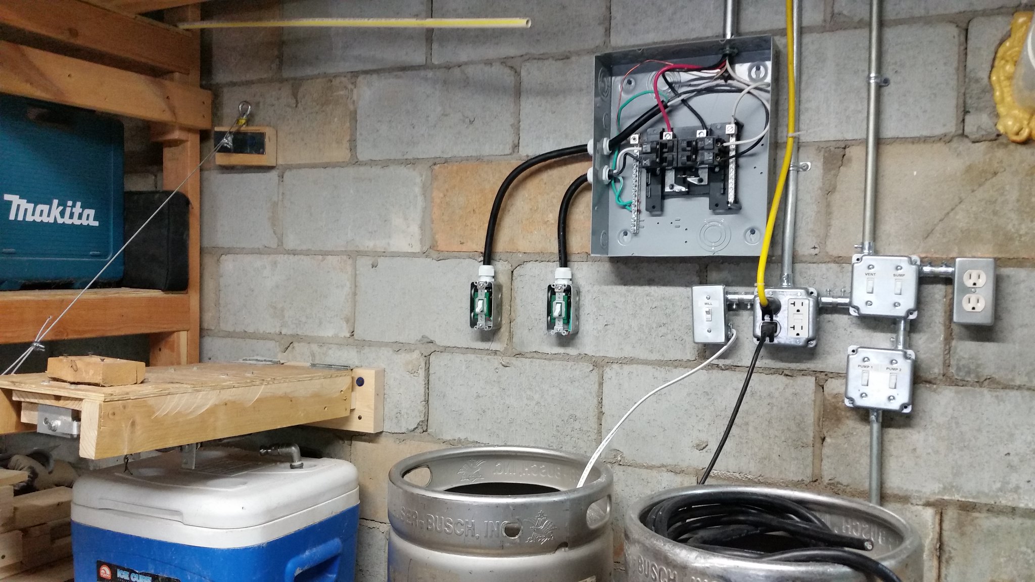
I will be pulling about 70 ft of 6/3 wiring from the main panel with a 50amp GFCI breaker. Will I need to run it in EMT conduit, or can I simply affix the wiring to the bottom of the rafters? This will be in a basement/garage.

I will bring the wiring down to where I will be brewing into a multigang box, from there, the multi gang box will be filled with three standard 240v wall switches rated for 30amps: http://www.homedepot.com/p/Leviton-...ble-Pole-Switch-White-R62-03032-2WS/100356941
That will then be connected to 30 amp dryer outlets: http://www.amazon.com/dp/B000FP8LEM/?tag=skimlinks_replacement-20 (so each switch controls one of the dryer outlets) mounted on the wall.

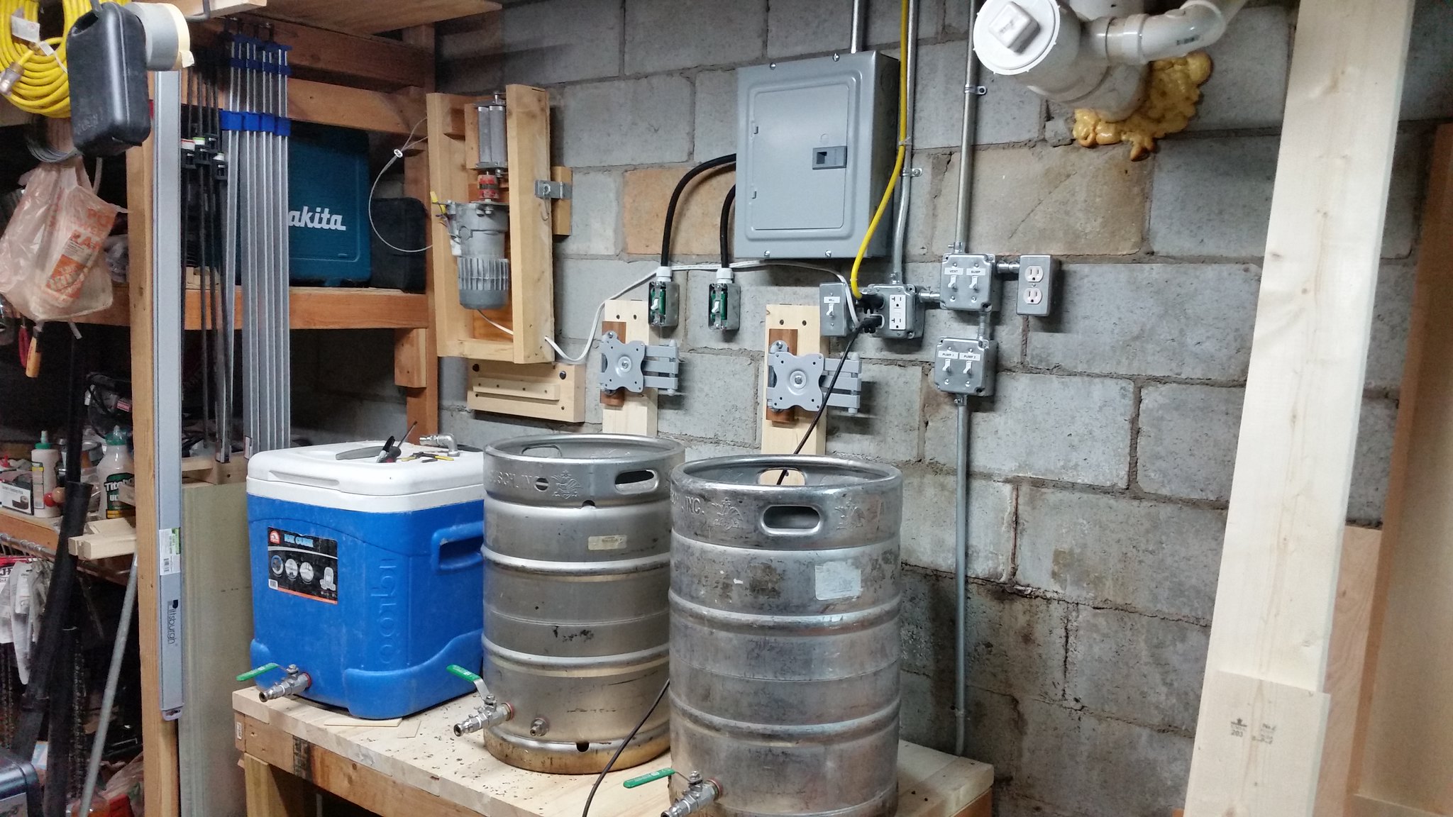
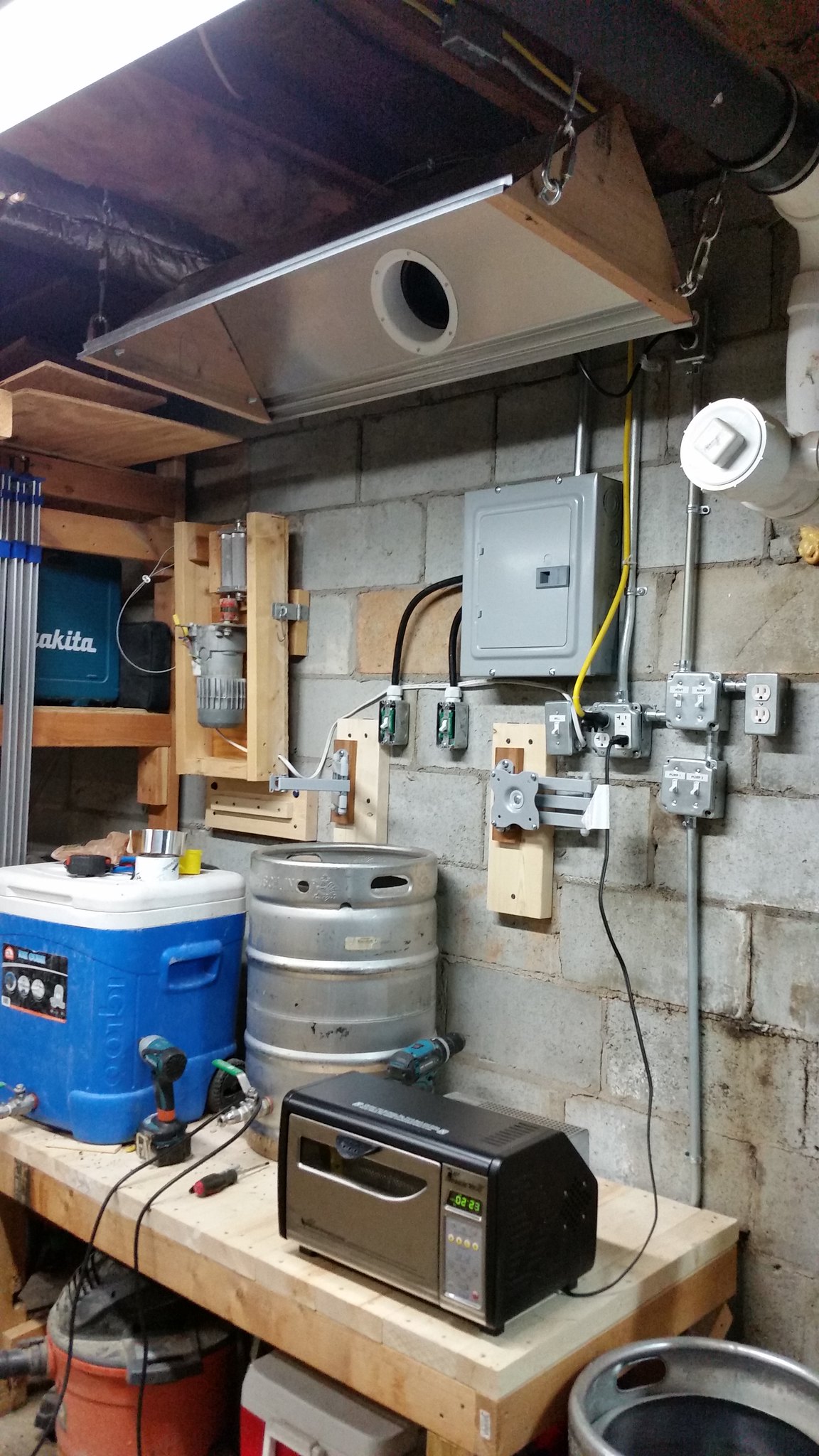
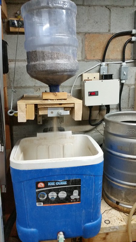
There will also be some 120v switches put in as well (most likely in an attached multi gang box) that will be used to switch outlets that control the vent fan, pumps, and grain mill (I plan on wall mounting the grain mill above the mash tun on a hinge).

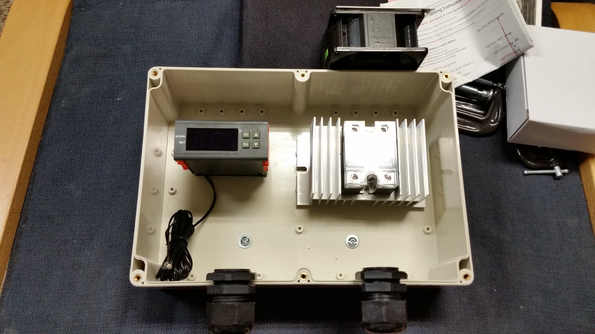
To cut down on costs and keep things simple, I was thinking about doing separate smaller control panels for the BK and HLT. I was planning on using the kit from stilldragon for the BK: http://stilldragon.com/index.php/diy-controller-kit.html

For the HLT, I am still figuring things out, but was planning on going with a 12vdc temperature controller to control the SSR (most SSR’s I’m finding are switched with 3-32 vdc). I already have a 12vdc power supply that I could use too. I will most likely use a thermowell in the HLT for the temperature probe

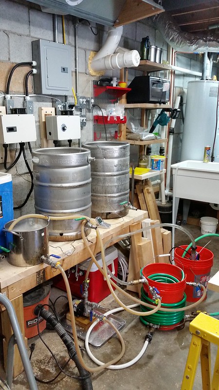
Both the BK and HLT will use 30 amp dryer cords connected to the wall outlets. The reason for the third is so that I can build a second BK in the future and then run a partigyle or dual concurrent boil (once I’m done with the HLT), that way I don’t have to unplug.

What I am thinking now though, is maybe just hardwire the 240v? I would need to get some 10 gauge wiring, but it could be cheaper, though not as flexible. I like the idea of being able to take down the control panels easily to repair or replace parts.

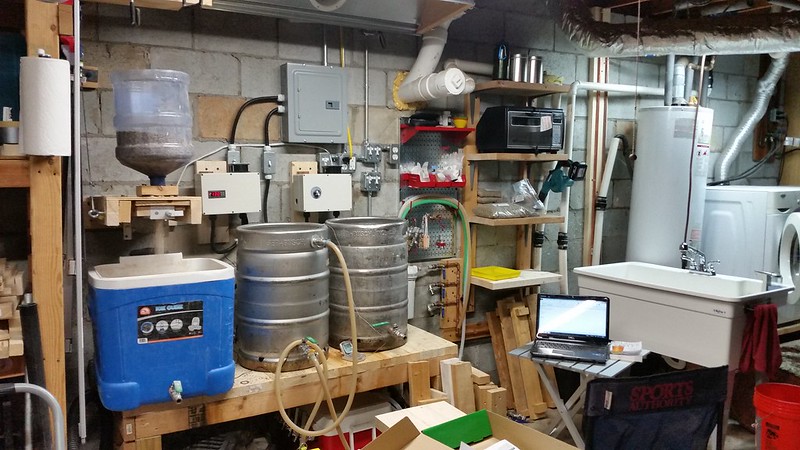
I know most do one big control panel, but I thought for myself that doing two smaller control panels would be easier and also cheaper. The wall is cinder block, and I was thinking about attaching a 2x8 to it which I would then attach a cheap monitor arm to for each control panel. I am essentially putting part of what most have in their control panel on my wall. I hope that makes sense.

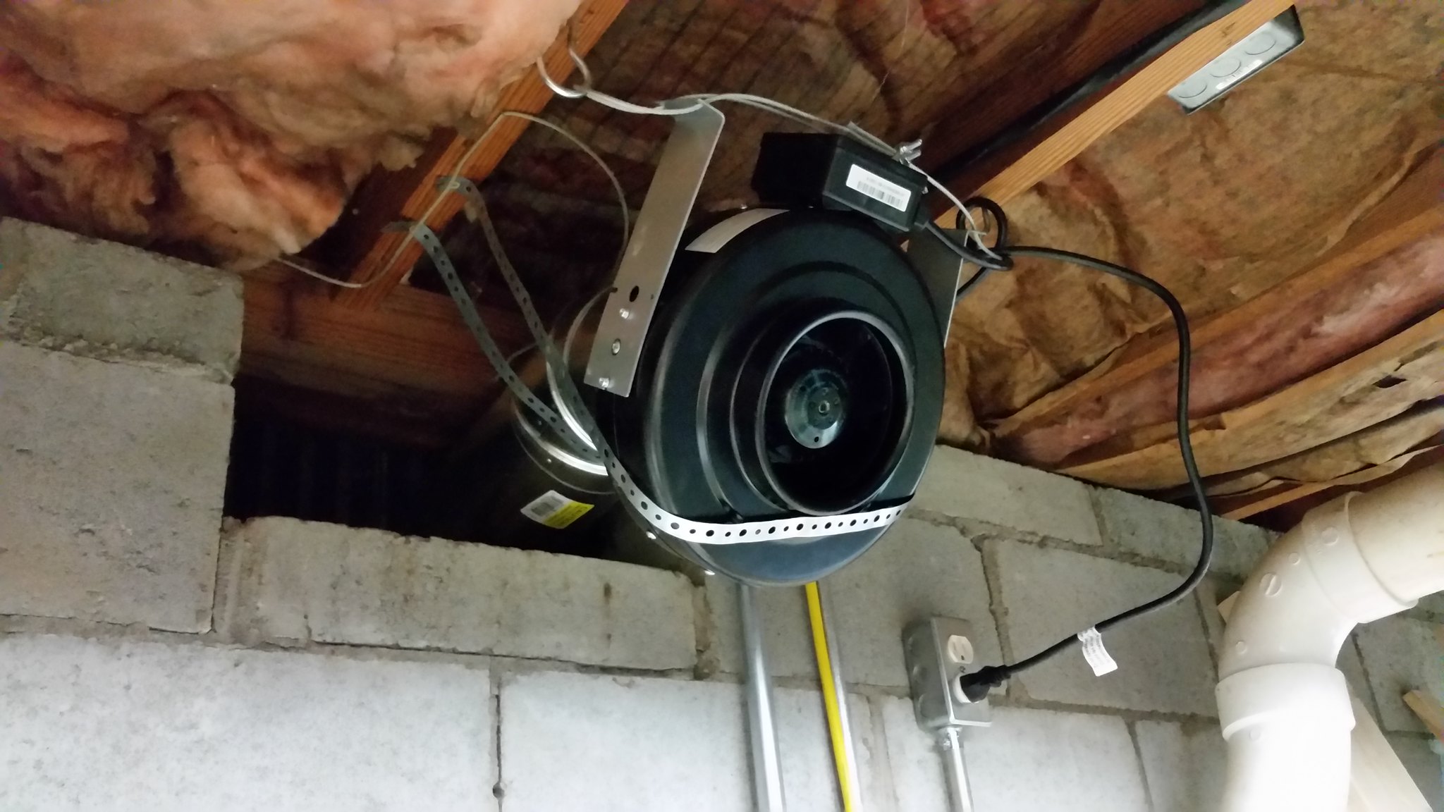
I was also planning on using this fan: http://www.amazon.com/dp/B006Z1JLY4/?tag=skimlinks_replacement-20
And then pipe it and build a cheap vent for the area. The FRP board vent hood build looks like something I could adapt.

I also wanted a big sink: http://www.homedepot.com/p/BigTub-U...PIPHorizontal1_rr-_-100029350-_-203155730-_-N

Which will allow me to clean right there, which I also have a sump pump for the washing machine that is close by that I should be able to drain to.

For the cold water line, I was thinking I should go ahead and sweat some copper and Tee off one of the lines that is overhead. For the hot water though, since I am so close to the washing machine, I was thinking of just getting a washing machine hose long enough so that I can split off of that for the sink. The cold water line I would split a few times to feed the water filter, chiller, and the sink.

For chilling, I have a dual stage counterflow that I built. I was planning on just running an extra garden hose out of the garage from the first stage using groundwater (I don’t want to fill up the septic tank), and then the second stage is with a submersible pump and ice water. I also have an immersion chiller that I could use in the winter time.

I also plan on building some cheap shelves on the side which will allow me to keep some things on hand, as well as store my coffee roasting equipment.

For my kettles, I was planning on getting the weldless bulkhead from stilldragon: http://stilldragon.com/index.php/2-triclamp-weldless-bulkhead-fitting.html along with their element guard kit: http://stilldragon.com/index.php/element-guard-kit.html

And then get 5500 watt stainless elements from one of the many vendors online (a lot of them seem to be out at the moment).

So how does this all sound? It is definitely still a work in progress, and I won’t be able to start on this for another month or so (other projects I need to finish first, and save up the money as well). I have changed the design in my head many times, but this is about where it stands at the moment. I am open to advice and constructive criticism. From my spreadsheet so far, it looks like I should be able to do all this within my budget, though it will be close after taxes and shipping costs!
 
Last edited by a moderator:
No thoughts so far?

I've already made some changes in my plan. Rather than just bring down the 6/3 wire, and try to split it to multiple outlets, which I was having a difficult time figuring out the best/safest method of, I am planning on using this sub panel: http://www.amazon.com/dp/B00002N7KK/?tag=skimlinks_replacement-20

The sub panel will have two 30 amp 240v breakers and two 20 amp 120v breakers to begin with, with plans to add another 30 amp 240v breaker later if needed(One 30a for the primary BK, one 30a for the HLT, and then the spare 30a for a possible secondary BK in the future so that I can run a dual boil once I’m done with the HLT, which could also just stand as a spare if an element burns out or the BK controller or SSR burns out). the 30a breakers will each be wired to a standard 240v wall switch rated for 30amps: http://www.amazon.com/dp/B00271GTQY/?tag=skimlinks_replacement-20 and from the switch to the mini control panel.

There will also be some 120v switches put in as well that will be used to switch outlets that control the vent fan, pumps, and grain mill (I plan on wall mounting the grain mill above the mash tun on a hinge). (I also plan on putting my coffee roaster in this area, so one 120v circuit will go to that as well most likely)

I've also decided to go ahead and hardwire the control panels to the switches using these AC Whips: http://www.homedepot.com/p/Liquidtite-10-3-in-x-6-ft-AC-Whip/202286686 since I won't need the neutral.

Any thoughts? I am still figuring things out in my head, and seeing how I come out on my budget. I believe I am doing pretty well right now, though I haven't fully accounted for all the small fittings, tax, and shipping for some of these items.
 
Last edited by a moderator:
I have a pretty simple basement build. I saved quite a bit by simplifying the control panel and sticking with a three tier gravity system. I modified the still dragon controller by splitting the feed with a 240 volt on off on switch. This allows me to have both the hlt and the boil kettle fired by the same controller. You need to watch the kettle thermometer but it worked with my previous propane system and it works with electric too.

If you can keep things to 30 amps you should be able to save quite a bit of money by not running 6-3 as 10-3 is much cheaper. At $2-$3 a foot the cost of $70 run is getting close to $200 with 6-3.

Also keep in mind you can't run nm cable(romex) in conduit. If you plan on using conduit you must use thhn individual conductor wires. Otherwise you need to drill and pull the wire through the joists.

image.jpeg
 
If going thru the trouble, I would plumb both hot and cold. The shark bite fittings make connecting to existing a breeze, they do cost a few bucks.

Sweating a tee in an existing wet line can be tricky, any moisture present will ruin the joint....old timers use the white bread ball trick to make a damn in the pipe and keep the joint dry while sweating in the tee.
 
I have a pretty simple basement build. I saved quite a bit by simplifying the control panel and sticking with a three tier gravity system. I modified the still dragon controller by splitting the feed with a 240 volt on off on switch. This allows me to have both the hlt and the boil kettle fired by the same controller. You need to watch the kettle thermometer but it worked with my previous propane system and it works with electric too.

If you can keep things to 30 amps you should be able to save quite a bit of money by not running 6-3 as 10-3 is much cheaper. At $2-$3 a foot the cost of $70 run is getting close to $200 with 6-3.

Also keep in mind you can't run nm cable(romex) in conduit. If you plan on using conduit you must use thhn individual conductor wires. Otherwise you need to drill and pull the wire through the joists.

Ah! I forgot to mention that I also talked with a friend who was an electrician for a while, and he told me I could just use wire staples on the bottom of the joists, so that is what I plan on doing now, and then pulling the last bit down the wall through conduit as a sleeve to protect the wiring.

This is the wiring I plan on getting: http://www.homedepot.com/p/Romex-125-ft-6-3-Black-Soild-SIMpull-NM-B-W-G-Wire-63950002/202316279

I know I will want to be able to run the BK and HLT at the same time, and possibly two boils simultaneously (after finished with the HLT, of course), so I definitely want to get a line that can handle 50 amps, and separate controls for each. I just don't want to shell out the money or time to do one of the nice big control boxes (I don't have the patience to wire something like that, plus in my estimation, doing the sub panel as I am will still save me money).
 
If going thru the trouble, I would plumb both hot and cold. The shark bite fittings make connecting to existing a breeze, they do cost a few bucks.

Sweating a tee in an existing wet line can be tricky, any moisture present will ruin the joint....old timers use the white bread ball trick to make a damn in the pipe and keep the joint dry while sweating in the tee.

Hmmmmmmmmmm, with the way the piping is for the hot and cold in the basement, there is a cold line going to an outside water spigot right where I am going to be brewing, so it should be easy enough to Tee of there (given I can get it dry enough, like you said). The hot water will be more difficult to pipe though, and since I don't plan on using the hot water for anything but the sink, I figure it will be ok to share the line from the washing machine.

As for the shark bites, I recall researching them years ago, and it seemed that among actual plumbers, they preferred sweating the copper, and had seen some failures of the shark bite fittings. I figure if I am going to be trying to do this, might as well sweat the copper. I may end up too frustrated and still go with the shark bite in the end though!
 
Ok, that works. I guess I'm a bit confused, yes an actual plumber might prefer sweating in a tee in that they are very adept at soldering, yet an actual plumber would insist on installing both hot and cold sink supplies rather than branching off a laundry supply with a flex hose. I think your chances of a leak are greatly increased connecting to the laundry supply vs shark bite fittings.

Point I'm trying to make is that you have a beautiful brand new sink and it would be nice IMO to have it fed properly.

Point well taken, I appreciate your gentle words. I will take another look at the piping to see if I can make it work to have both hot and colds properly piped.

I do understand the oddity of wanting to sweat the cold and jerry rig the hot. I think where I am coming from is what is most important and most used. I know I will be using the cold a lot for everything, and the hot for only small tasks. I'll see if I can find a good spot to do the hot side properly too though.
 
Ok, a long washing machine supply has different fittings than a sink supply...but anyways....post a pic of your washing machine supply piping....might be simple to tee right there for everything.

Shark bites lol....might be as simple as cutting the existing and snapping it all together.
 
What I was planning on doing for the hot water was to use a stainless 1/2'' Tee and just use fittings for whatever threading I needed. For the washing machine, it uses garden hose threads, so that is easy enough. The only unknown is the threads for the faucet connection. My original plan was to just go to home depot with the faucet, and find the proper fitting needed - ideally one that can go from the faucet hookup to 1/2" NPT so I could just attach the Tee directly there.

I'm going to take another look tonight though and see if I can figure out a reasonable way to pipe both the hot and cold using soldered fittings, as that would definitely be the best route to take.

For some reason, I just have an inherent distrust for long term durability of the sharkbite style of fittings for this purpose. I use push to connect fittings all over my brewery and serving setup, but I don't expect them to last for decades. I don't want to have an emergency due to a water leak later on down the road.
 
You should be fine with the Sharkbite Poly tubes, in my area they are requiring them as "code" when installing or repairing boilers in homes. If they can hold up the the extreme use and heat in a boiler setting, you'll be fine on a brewing setup.

The only thing I heard (and it may have changed by now) is that the Poly is not supposed to be exposed to UV (sunlight) for extended periods of time. If it will be installed in a wall or a basement where not much sunlight gets in throughout the day, you're good to go. Again, that was a few years ago I heard tat and things could have changed since then. Just look at the side of the poly tube, it will be printed on the side to not expose to UV lighting.
 
I think I'll be able to solder in both hot and cold now. It won't be pretty, but it should be functional, and also expensive with the cost of copper nowadays!

What I am thinking more about now is the heat inside the control panels. How much airflow would the SSR need to stay at a reasonable temperature? I am thinking that I'll just cut out holes for intake and exhaust with a small computer fan mounted at the intake.

My other thought is to make a cutout for the SSR to be able to mount the heatsink outside of the box, but with no forced airflow around it, I'm not sure if this is a better idea.
I went the route of the pc fan on my build below... I even have one dual ssr mounted to a $3 heatsink that controls both my rims and hlt. The 12v fan keeps it cool.
 
I thought I'd update with some progress. I've been working on this little by little. I've got some other projects that I am trying to also work on, so I need to split my time, plus I need to finish the other projects to free up some space in this area too.

Here is when I was wiring the infrasture:
26805904795_1b142fc4df_k.jpg


Here is another view later on with things more mocked up with where I will want them:
26534034850_e8761d1ff9_k.jpg


Here is the 6" inline centrifugal fan mounted:
26805894545_768038b212_k.jpg


Here is the vent hood attached:
26534029130_6200b04248_k.jpg


Here I am mocking up where I want components inside the HLT control panel:
26805899685_550acb386b_k.jpg


I still need to cut the holes in the kettles and silver solder the tri clamps in, cut and wire up the control panels (I'm going to do the HLT first and run a test), and I still need to do all the plumbing, but I'm still waiting on the valves, and lumber from my other project is also in the way. Honestly, the plumbing is a lower priority right now, so it may be a while before I tackle it, even after I get the valves in.
 
I was reading in the book "Yeast" a recommendation to not mill your grains near where you do your cold side of brewing - since the grains have lacto on them and the dust gets everywhere... I see you have your grain mill mounted to the wall. Good idea, but you may want to consider the dust issue.
 
That is definitely a good thought. I think what I will do to help prevent infections, is to use the vent hood while I mill. I know it won't necessarily get everything, but considering it has a flow rating of over 400 CFM, I think it can definitely help.

I do like having the mill permanently mounted and out of the way when I don't need it, so I'll work with it as it is, and if I have issues, I'll reconsider. Thanks for the input!
 
Well, it is complete!
27010551586_38521c8b97_c.jpg


I've done a quick water run through of the system, and it works quite well!

I had to change out the stainless valves for solder valves since I couldn't get them to seal well, and one was even weeping water through the stainless wall as if it were sintered! I have one valve for the water filter with a GAC-10 filter, one valve with a camlock to flush the lines, and one valve with a garden hose disconnect for cleaning purposes. It is also Teed off for the sink.

I am using John Guest fittings and Bev Seal Ultra to go from the valve to the water filter, and from the water filter to the HLT. These were left over from my faucet upgrade last year.

I have a stainless thermowell from brewhardware in the HLT with thermal grease on the temperature probe to reduce drift.

You can see the wall mounted mill in the down position with the 5 gallon plastic carboy as the hopper.

I put in wall control metal pegboard on the wall, as well as built shelves. The shelves are primarily for my coffee roasting equipment though.

I did install the sink, did all the copper sweating, and plumbed the sink to the sump pump that was already there for the washing machine.

Most of the other details are already in this thread, but I'll do a quick run down:
separate control panels for HLT and BK, each with their own 30 amp breaker and wall switch
ran 6/3 to a sub panel for a 240v, 50 amp capacity with GFCI in the main panel
vent hood, mill, and pumps are all on wall switches, as well as the sump pump for ice water recirculation
brewhardware silver solder 2 inch tri clover fittings for the kettles
Stilldragon element enclosures
5500 watt high density elements (ripple elements didn't fit through the enclosure, I tried)
HLT is using a 240v temperature controller to a 40 amp SSR to run the element (it took quite a bit of time to find a 240v controller that displayed in Fahrenheit!)
Stilldragon DIY controller kit for the BK running a variable SSR dictated by the rheostat resistance
Both control panels only have 240v inside, and I added a 240v exhause fan on top that pulls air directly over the SSR heatsink inside
utilitub big sink 40x24 Outside dimensions with hot and cold water
vent hood using a 6 inch inline centrifugal fan with a homemade hood using galvanzed sheet metal roofing material and wood end caps and a 6 inch flange to connect to the fan
Single chugger stainless center inlet pump, but I wired another switch and plug so I can add a second pump very easily

As far as my brewing setup, you can see the two keggles as well as the 60 quart cooler as my primary mash tun. I also have a 120 quart cooler for really big beers.

Well, that's all I can think of for now!
 
Well, I've finished the first batch. I decided to keep it simple with a 5 gallon batch of cream ale. I actually don't really like the style that much, but it is a simple and cheap one to start with just in case if I need to dump it!

Also, even after feedback about not to worry about scorching, I wanted to do my own test to make sure to remove any lingering doubts.

I started last night to heat the strike, mill, mash in, and fill the HLT with the sparge water. All of that from turning the first valve to putting up the mash paddle was just at 30 minutes.

Then, today, I started heating the sparge water that was already filled in the HLT, vorlaufed, and then transfered to the BK, sparged, then started the boil. Every heating step essentially took around 15 minutes, which was pretty amazing. It took 15 minutes to heat the sparge water to 185F, and then just over 15 minutes to get to boiling.

I timed the work I did today, and from switching on the HLT to turning off the light after cleaning was 2 hours 10 minutes. I started cleaning at around 1 hour and 46 minutes to my recollection, so cleaning took a very long time today, and I did make a mess of it. This is when I really wish I had a floor drain, and I could just wash everything down there. I had to use a towel at the end to wipe up some of the mess I made.

So total time that I had to be there was right around 2 hours and 40 minutes, which astounds me, especially given that I did make a number of mistakes. This really opens some possibilities for me in terms of being able to brew around my family schedule. I think I'll be able to manage it so that in the future after getting home from work, I'll be able to spend the 30 minutes to mash in and get the sparge water ready, and then after the kids are put to bed, I do the rest of the brew day in two hours.

The first mistake I made was last night. I started milling, and I had forgotten to remove the lid to the mash tun, and was milling onto the lid. Haha. I couldn't believe I did that. When I was brewing with propane outdoors, I had to wheel the mill out, and would always remove the lid to the mash tun before putting it under the mill, so I had forgotten to remove the lid after I had just put the mill down from the wall.

I also forgot to close the valve after mashing in, and there was some backflow before I caught it.

While cleaning, I had forgotten where I had put the exit tubing from the pump, and I started pumping leftover wort all over the table. At one point, the silicone tubing also slipped out of the fermenter while filling, but I was right there, so that wasn't too big of a mess.

Part of the cleaning issue is that I am trying to get everything over to the sink. I am wondering if I need to have a more permanent plumbing setup to make this easier - mounting tubing on the wall with camlock fittings, with tubing routed up the wall, across the joists, and down to the sink. Now that I am thinking more about it, I could get more copper pipe, mount it to the wall, with a camlock by the brew stand, and a simple exit to the sink, maybe some tubing for the last bit so that I don't have a copper pipe jutting into the sink area.

Man, it looks like a mess when I am chilling though, I have a small pot that I use to recirculate star san through the dual counterflow while I am in the boil. I have the march pump hooked up, I have a hose coming from the wall for the first chilling stage, with another hose going to the sink to drain the hose water coming out of the chiller, then I also have a sump pump in a bucket of ice water with a hose going in to the second stage, and another hose recirculating back into the bucket. Trying to disconnect these and purge out the liquid at the end took me a while to figure out to minimize spilling, and even then there was a lot of water on the ground at the end. Haha.

26847223840_51bf9b0ab3_c.jpg

26517592253_7371940934_c.jpg

26847209850_b440376e93_c.jpg

27121443275_9ddc8d8554_c.jpg
 
Back
Top