SVEBS Build

Homebrew Talk - Beer, Wine, Mead, & Cider Brewing Discussion Forum

Help Support Homebrew Talk - Beer, Wine, Mead, & Cider Brewing Discussion Forum:

This site may earn a commission from merchant affiliate links, including eBay, Amazon, and others.

urbangravity

Well-Known Member
Joined
Jun 18, 2012
Messages
81
Reaction score
4
Location
Lancaster
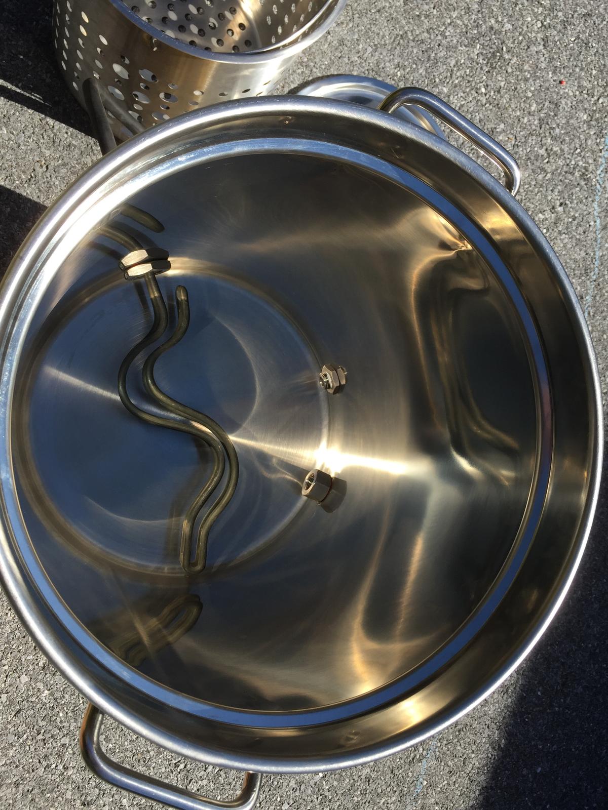
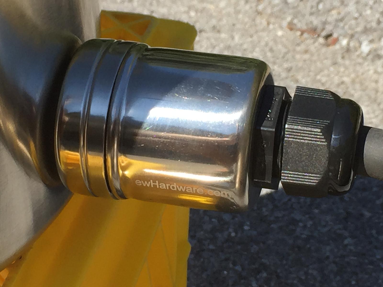
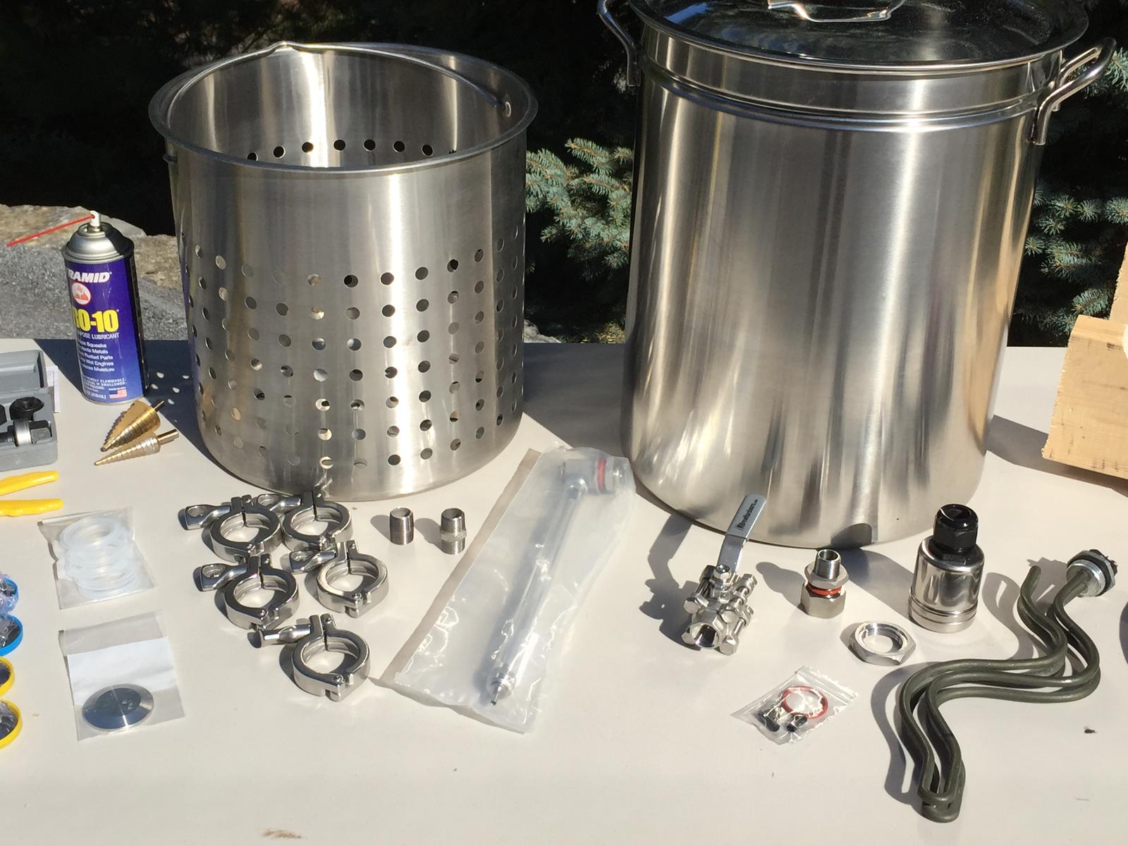
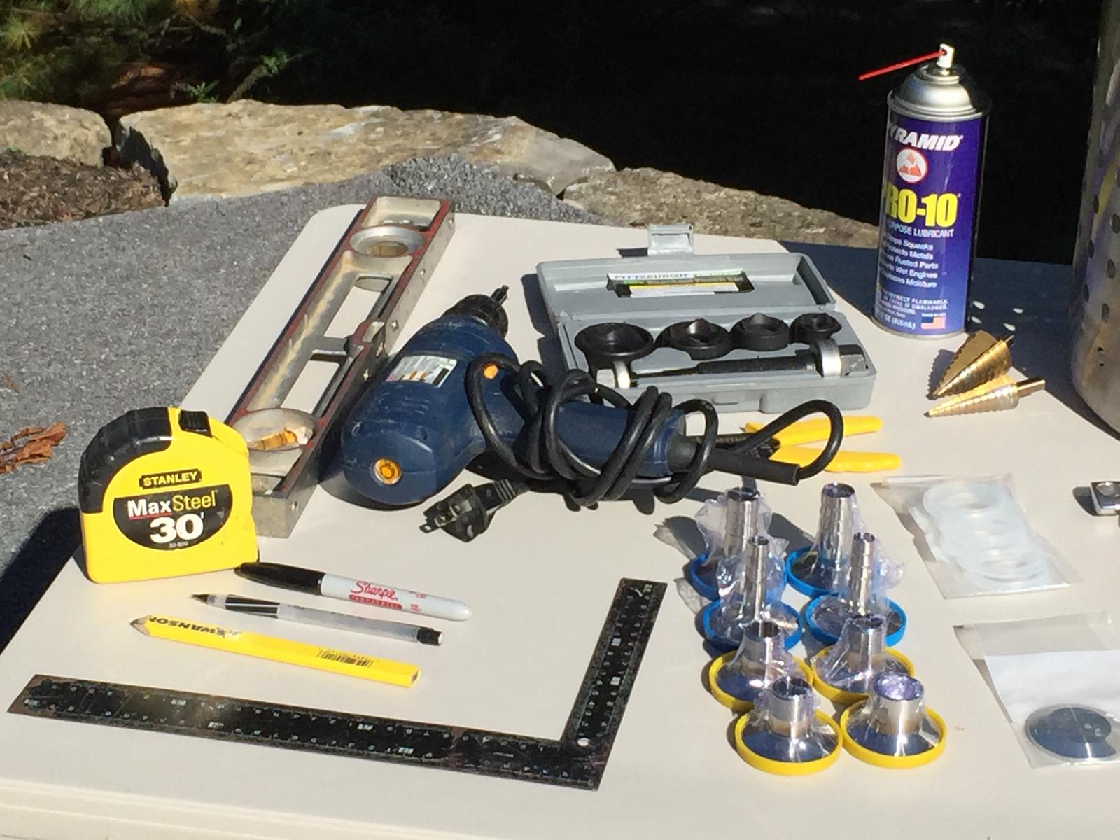
After having a 1/2 barrel, three vessel, gas fired, BCS controlled brew system and looking at the $3000 turn key German systems that undoubtedly would require factory service is something fails, I decided to build a Single Vessel Electric Brewing System that I can service and provides automation in a small package. These shots are from the first phase, the kettle build. Since working with a round kettle can be awkward, I built a cradle out of a spare 2 x 6 I had in the garage. Made hole cutting a lot less challenging. Also attached is my complete parts list and total cost. The control panel will be next and thanks to Aubiecat and PJ for all their great posts and diagrams.
IMG_1589.jpg


IMG_1588.jpg


IMG_1590.jpg


IMG_1592.jpg


IMG_1593.jpg


IMG_1595.jpg


View attachment Brew Kettle Part List.pdf
 
The kettle is a Bayou Classics 1144 so 11 gallons. I chose the setup because it had the basket and offered enough space below to fit the element in. Frankly when I drilled the holes I was underwhelmed with the thickness but functionally is works and the price was great.
 
Some updatesImageUploadedByHome Brew1413735634.166742.jpg
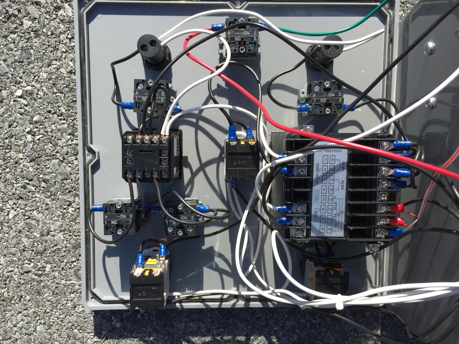
Face plate with components

installedImageUploadedByHome Brew1413735719.842214.jpg
Components and hole cuts

ImageUploadedByHome Brew1413735814.919423.jpg
SSR hole cut

ImageUploadedByHome Brew1413735870.642143.jpg

ImageUploadedByHome Brew1413735946.901525.jpg
Hole cuts on back of controller for connections

Now the wiring starts!


Sent from my iPhone using Home Brew
 
I got that unit at Brew Hardware. Here's the description. #5 EWL3 - Bare Enclosure w/ 1in locknut and oring , Cord Grip Size: LARGE for 13-18mm OD cable
 
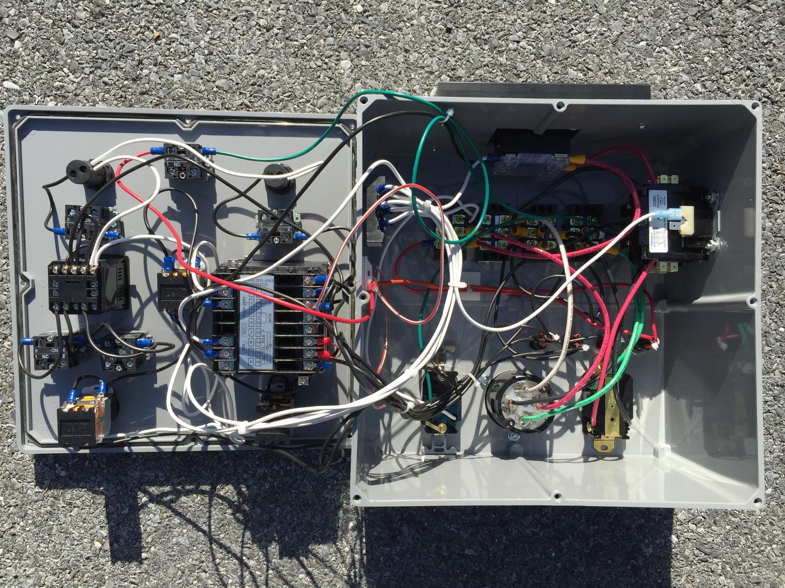
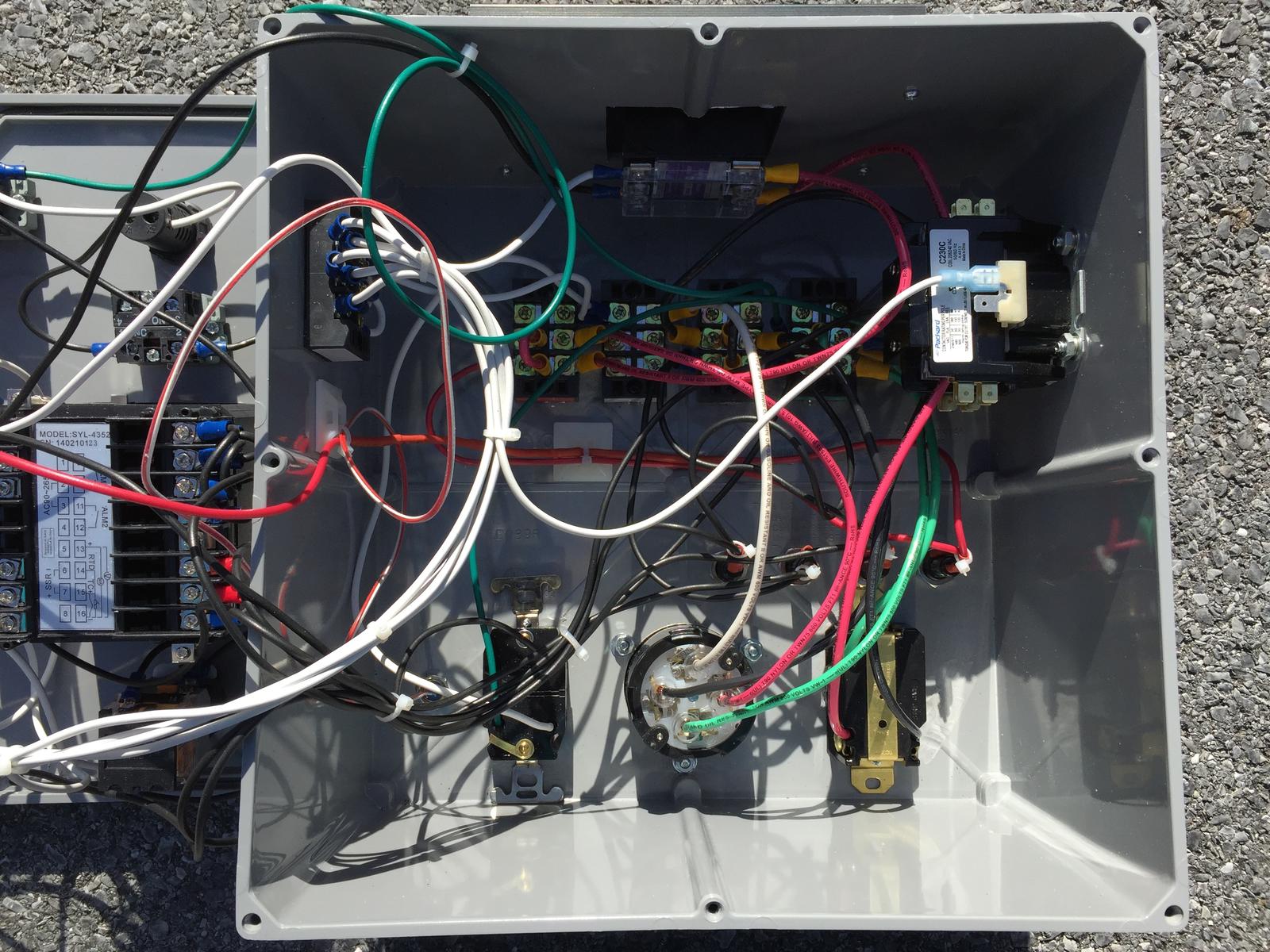
Power side of of box. Anybody see anything wrong please let me know. Certainly not as neat a job as Aubiecat. Next, I will post the one mistake I will hope keeps anyone seeing this from making.

IMG_1699.jpg
 
HERE'S THE MISTAKE I WOULD DEFINITELY DO DIFFERENT. DON'T USE MY TERMINAL BLOCK PLACEMENT. Way to close together and the connectors on both sides hit the ones on the next block. Also I would place them in a row, not side by side. Bent the connectors upward a bit as you'll see in the photo. You can also see that each block was attached with two screws. I also put some epoxy on the backs of the terminal to keep them in place if the screws loosen.

IMG_1700.jpg
 
Here's the back of the controller with all the fuses and connections. I designed it this way with the connections coming straight off the back since I will sitting it upright on a work top.

IMG_1692.jpg
 
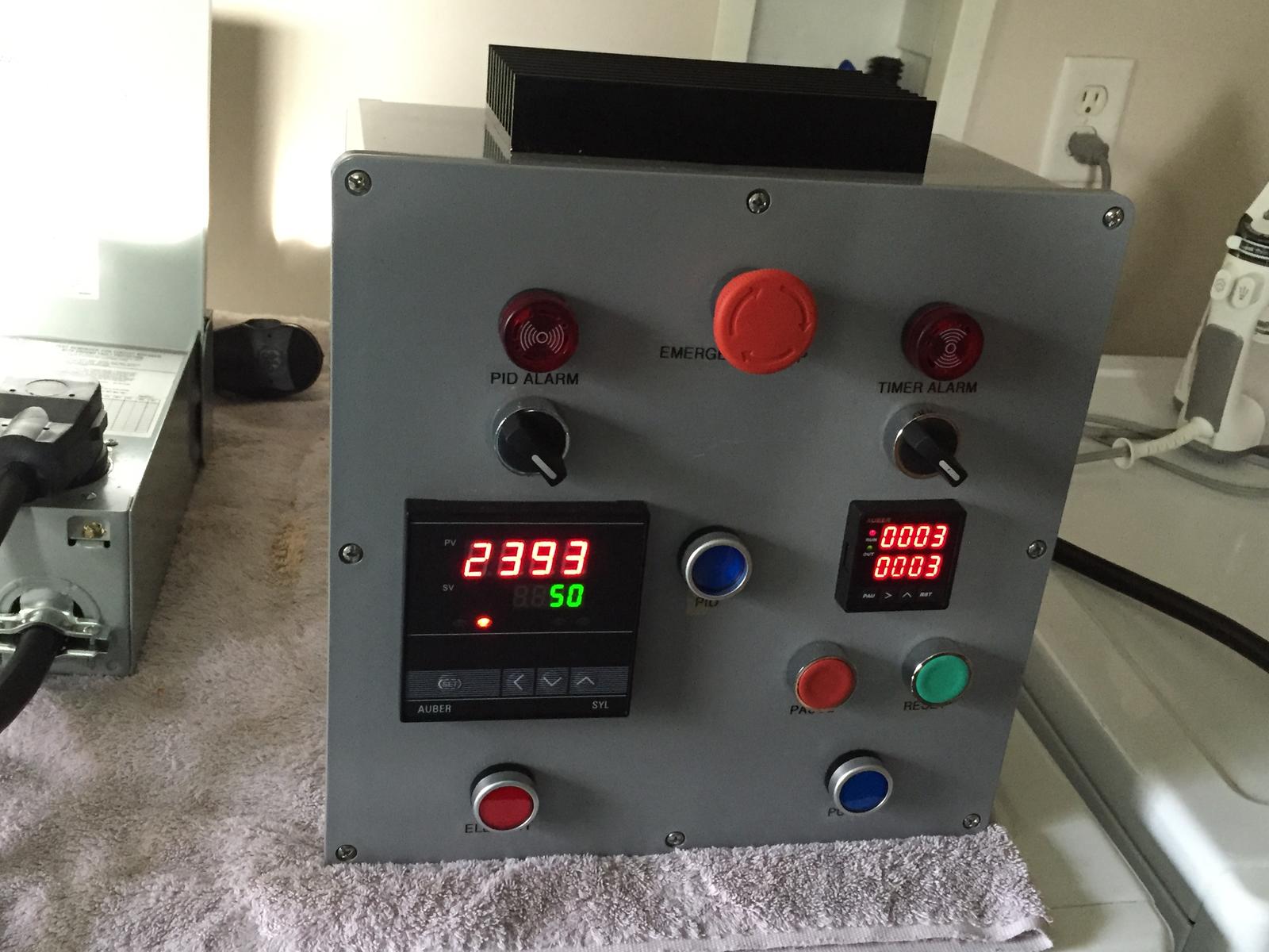
SUCCESS!!! I didn't blow anything up. You can see the spa box in the background. Again, I used Aubiecat's great project description for that piece. I do want to thank PJ and Aubiecat for posting such great resources. Only thing a bit confusing is why the PID power button didn't light up when I powered it on. I triple checked my wiring but I'll have to look into that to make sure I picked the lighted switches from Auberins.

IMG_1703.jpg
 
NOT BREWING YET! After getting everything assembled it was time for the water test. Since I don't have a GFI on my 30 amp service (dryer plug in the laundry room), I built the spa box (home depot) that worked perfectly. I did uncover a couple issues:

1 ISSUE - The blue SW1 switch for the PID power did not illuminate. I think it is defective and have written Auberins. It powers the controller on and off with no issue so I am thinking the LED is blown. Triple checking, he switch is wired according to schematic properly.

2. Pump button and alarms all working and illuminating properly.

3. Both timer and PID turned on and functioned properly including the temperature probe operation after setting the input type to RTD.

4. ISSUE - The heating element did NOT heat at all. Made a noise but no heat. I went back to the drawing board that triple checked the wiring and components since it seemed to be in the contactor, relay, controller and switch operation. Also the red SW1 switch for the heating element did not illuminate fully (very dim). I checked the parts and found that I ordered a 240v coil contactor, not a 120v. It was confusing since I ordered parts directly from PJ's schematic and it was labeled "contractor 240v - 30A - 120v Coil". I also went back to Aubiecat's build and saw that he used a 120v, so I ordered one and am hoping that will solve this issue.

More to follow after these corrections are made and tested.
 
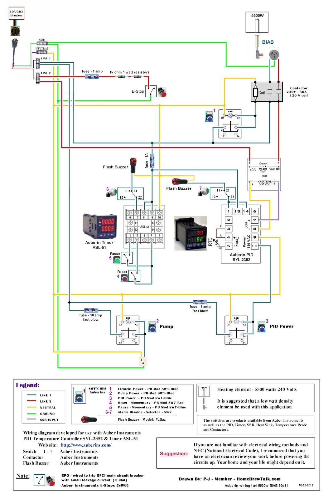
This was the schematic that I used for the project. I will update if the heating issue is solved by installing the 120v contractor after my next water test.

Auberin-wiring1-a4-5500w-BIAB-30d11.jpg
 
Also, if you like the larger PID display (SYL-4352), here are the terminal matches from the 1/16 PID (SYL-2352), shown on this schematic.

PID
2352 - 4352

TERMINAL
1 - 9
2 -
3 - 14
4 - 15
5 - 16
6 -
7 - 7
8 - 6
9 - 2
10 - 3
13 - 10+11 jumpered
14 - 12
 
NOT BREWING YET! After getting everything assembled it was time for the water test. Since I don't have a GFI on my 30 amp service (dryer plug in the laundry room), I built the spa box (home depot) that worked perfectly. I did uncover a couple issues:

1 ISSUE - The blue SW1 switch for the PID power did not illuminate. I think it is defective and have written Auberins. It powers the controller on and off with no issue so I am thinking the LED is blown. Triple checking, he switch is wired according to schematic properly.

2. Pump button and alarms all working and illuminating properly.

3. Both timer and PID turned on and functioned properly including the temperature probe operation after setting the input type to RTD.

4. ISSUE - The heating element did NOT heat at all. Made a noise but no heat. I went back to the drawing board that triple checked the wiring and components since it seemed to be in the contactor, relay, controller and switch operation. Also the red SW1 switch for the heating element did not illuminate fully (very dim). I checked the parts and found that I ordered a 240v coil contactor, not a 120v. It was confusing since I ordered parts directly from PJ's schematic and it was labeled "contractor 240v - 30A - 120v Coil". I also went back to Aubiecat's build and saw that he used a 120v, so I ordered one and am hoping that will solve this issue.

More to follow after these corrections are made and tested.
your can easily wire the 240v contractor coil to still work fine for this setup... just change out the neutral for the other hot leg to the coil....
 
Not an electrician and agree that didn't make sense to me but I looked at Aubiecat's actual photos and parts list and he used a C230B which is a 120v coil. Moreover his system worked and mine didn't and that was the only difference that I could see. He used a camco 5500w/240v element.


Sent from my iPhone using Home Brew
the coil just actuates the switch in the relay... to change the wiring in your design you simply swap the neutral going to your coil with the L2 wire to supply 220v to the coil instead of 120v... with 120v theres not enough power to "energize the coil" and make the relay contacts close. so simply run a jumper wire from your red line coming in to where the yellow currently is on your existing diagram once you remove the yellow wire (without going to the switch since "L1" is still being switched it will still work)... its that simple.
 
So let me see if I understand. If I remove the neutral lines going to X1 on the element switch and the coil (shown in yellow), I can run an Line 2 (red) wire directly from the terminal block to X1 on my element switch and then to what was the neutral connection?


Sent from my iPhone using Home Brew
 
Ok, I wrote the last before seeing your full explanation. So, the neutral line goes to and stops at X1 on the switch but does not go to the coil. A L2 wire goes directly to the previous neutral coil connection?
 
I posted an edited schematic that I believe shows this wiring option but Augiedoggy can confirm if it accurately show what he describes
 
For the problem you're having with the illuminated switches, make sure that the color of the Led bulb is matched with the same lens color. I made the mistake in my build of assuming that just the lenses were colored and got them mixed up, which results in the varying brightness you're experiencing.
 
Thats interesting and could be what is happening. Can you tell the bulb color by popping them off and taking a look in the button or switch?


Sent from my iPhone using Home Brew
 
This was the schematic that I used for the project. I will update if the heating issue is solved by installing the 120v contractor after my next water test.

Looks like the timer is always powered up, as is the alarm light/buzzer for the PID, whenever the control box is connected to power. Is this correct? And, if so, why is it done that way?

Brew on :mug:
 
The timer is always on which I didn't realize till I powered everything up. I might add another SW1 to switch it off/on or use the existing PID switch to power both. The PID buzzer is only functional when the PID is powered on


Sent from my iPhone using Home Brew
 
Bsperr, you were right! The LED SW1 switches got mixed up and are specific to each color. My element switch looked purple and was suppose to be red. Thanks to your post, I switched them and they are the right color now. Thanks


Sent from my iPhone using Home Brew
 
The timer is always on which I didn't realize till I powered everything up. I might add another SW1 to switch it off/on or use the existing PID switch to power both. The PID buzzer is only functional when the PID is powered on

But there is power to one of the alarm terminals, even when the PID is off, unless I'm missing something. Any reason not to put the timer on the same switch as the PID, and switch both alarm powers thru that switch as well?

Brew on :mug:
 
The power to both buzzer switches comes from each unit individually. The buzzers both do connect to a neutral line but the power that makes them sound and light comes from the ALM terminals on each the timer and the PID. At least that is what I take from it. The buzzers only operate if those units are on but you are right, the timer is not switched and alway on, something I can change by jumping terminals 2 and 3 on the PID with terminals 10 and 9/8 on the timer, respectively. You could actually eliminate the one fuse that comes to the timer from L2.
 

Latest posts

Back
Top