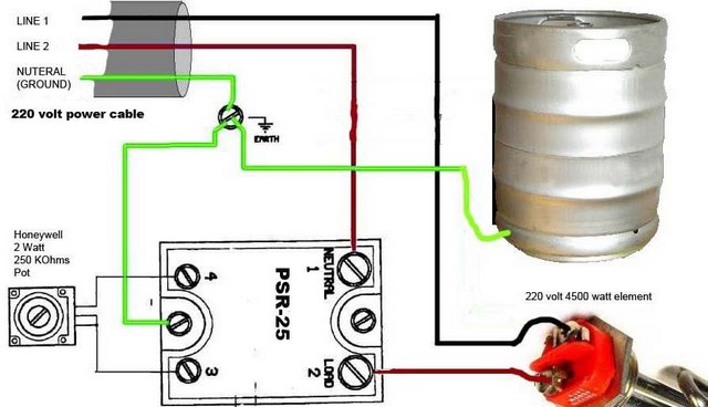
How does one wire an ammeter and a 3 selector switch into this box?
I'd like to pick up one of these but I want an ammeter for precise control as well as a 3 selector switch (two elements with off in the middle) to switch from one element to the other.
I'd like to pick up one of these but I want an ammeter for precise control as well as a 3 selector switch (two elements with off in the middle) to switch from one element to the other.