Stc-1000+

Homebrew Talk - Beer, Wine, Mead, & Cider Brewing Discussion Forum

Help Support Homebrew Talk - Beer, Wine, Mead, & Cider Brewing Discussion Forum:

This site may earn a commission from merchant affiliate links, including eBay, Amazon, and others.
I'll be checking things over with a multimeter today and report back on how things go. My boss will also help me with soldering the pins in (I was just holding the header to the back of the STC-1000).

I should have mentioned that before attempting to flashing the STC-1000, I previously used it in my fermentation chamber and it worked ok. So if it is broken now, I only have myself to blame :p

Thanks to everyone thus far on all of your help!

I had a few failed attempts to flash one of my units and found a few points to be sure of:
1. Make sure you are reporting the correct com port.
2. Make sure yo have the correct baud rate.
3. Ensure the Dupont wires are pushed all the way into the Arduino.

My unit had one solder pad that was missing a good bit of solder. It wasn't until I soldered the wires to the STC board that it flashed successfully.

Thanks to Alpha, Will and others ... even this old man with weak eyes and zero electronics experience was able to pull this project off (3 times).
Cheers!:mug:
 
First post ever! I'm from Argentina :)

Just to thank alphaomega and to let everyone know that the flashing process also works with an arduino nano v3 board.

Also I compiled using linux and avr-gcc, so I had to add functions declaration at the begining of the code for it to be happy. Maybe you could include that alphaomega? This was using the stable version.

I'm running a profile test(and logging temps) before using it in a real beer.
 
i apologize if this was posted previously...has anyone made a programming cable of some sort? I just built my controller and after wiring it all up, i'm not looking forward to the complete disassembly of it to reprogram.

I was thinking maybe a CAT5 cable a RJ45 jack mounted to the housing(not the STC1000 itself)?

Excellent work alpha! I havent used it for fermentation yet, but have it hooked up to my kegerator. I plan to use the kegerator as my fermentation chamber once my keg is empty.
 
First post ever! I'm from Argentina :)

Just to thank alphaomega and to let everyone know that the flashing process also works with an arduino nano v3 board.

Also I compiled using linux and avr-gcc, so I had to add functions declaration at the begining of the code for it to be happy. Maybe you could include that alphaomega? This was using the stable version.

I'm running a profile test(and logging temps) before using it in a real beer.

Cool!
Thumbs up for using linux and also avr-gcc straight (though I guess you still need to link to the arduino specific library). I also much prefer straight C and avr-libc over Arduino IDE.
I sure could include the function declarations, but really, Arduino preprocessing will o this for you, and if you want to use avr-gcc straight, then you probably know what you are doing anyway...
I'll try to include them when I get around to it.
It is really cool to hear that STC-1000+ has reached Argentina :)

i apologize if this was posted previously...has anyone made a programming cable of some sort? I just built my controller and after wiring it all up, i'm not looking forward to the complete disassembly of it to reprogram.

I was thinking maybe a CAT5 cable a RJ45 jack mounted to the housing(not the STC1000 itself)?

Excellent work alpha! I havent used it for fermentation yet, but have it hooked up to my kegerator. I plan to use the kegerator as my fermentation chamber once my keg is empty.

Programming connector is a good idea. I don't recall anyone has used RJ45, but if that is what you have at hand, I see no reason that won't be just fine.
 
I can now also verify that using an Arduino Pro Mini (5v with atmega328) and CP2102 USB to serial works well to reprogram the STC. Under Linux it worked out of the box, you might need to install an USB driver under Windows.
A bit more soldering, but on the other hand, this combo can be had for less than 5 bucks on ebay (search "CP2102 pro mini 5v").
Sorry for the crappy pics, but I hope you get the idea...

2q33ak3.jpg


2unty7c.jpg
 
Holy fermentation controller batman!

Ok, I haven't really done much code wise or so this weekend, but I think it has been a pretty good one for the STC-1000+ project anyway. I think that using $5 equipment for a programmer is pretty cool, when the intended programmer (PIC kit 2) costs probably 10-15 times more.

And today I made another discovery. I noticed that just next to the screw terminal for the thermistor, there is an unused solder pad.

2jtjro.jpg


It just 'happens' to be routed to ISCPCLK, the only pin not used in normal conditions (i.e. when not flashing). In the picture you can see that there even are pads for an SMD resistor and SMD capacitor (R3 and C3), same as for the NTC input (R2 and C2, to the right in the pic, but kind of unreadable...). And yes, RA1 (the generic pin that ICSPCLK is on) also functions as A/D.
It is "almost" as someone designed this board to be able to handle TWO thermistor inputs. :rockin:

Why is this awesome? Well, it seems that with a little bit of soldering, and some cheap SMD components off ebay and some of blood, sweat and code (at least on my part), we could have an extra temperature input. This could be used for things like measuring fridge temperature, making sure it does not shoot off too far before beer temp catches up (limit over/under-shoot). Or when I get around to finishing my mash firmware, you could measure mash temp AND output temp from RIMS.
Heck, if you are able to code yourself, you could use it for anything. Not only an input. SSR output? Float switch?
I am gonna try to enable a secondary temp reading. Personally I think it would be cool (pun intended) to be able to set limits on fridge temp (like the hysteresis).

As best I know now, what you would need is a new 3 pole screw terminal (5mm pitch) to replace the 2 pole. And an SMD resistor and capacitor (probably 0603 form factor) and an extra NTC thermistor (B3435). The resistor is 10K with as good accuracy as possible (1%?, this is part of the voltage divider with the NTC). The capacitor should not be as critical, from what I could find with google 10-100uF is prolly in the right range.

Cheers!
 
That is really cool, Nice discovery! I really like the idea of a float controller, should be nice and simple too.
 
Would it be possible to have a separate hysteresis for cooling and heating? I know the memory is getting quite full, not sure if it is possible or not. I'm trying to tighten up my overshoot and undershoots a bit more and prevent excessive heating and cooling. I'm using a cooling jacket and a heat wrap, and they don't quite change the temp at the same rates.
 
Would it be possible to have a separate hysteresis for cooling and heating? I know the memory is getting quite full, not sure if it is possible or not. I'm trying to tighten up my overshoot and undershoots a bit more and prevent excessive heating and cooling. I'm using a cooling jacket and a heat wrap, and they don't quite change the temp at the same rates.

This has been discussed earlier I think. I probably could be done, but I don't think it is the right thing to do. Why would it be more ok (okayer?) for temperature to drift in one direction but not the other from the setpoint? Bottom line is, if your heater and cooler are mismatched, then best would be to try to sort that.
If your heater is to effective, try to limit it. If it pure resistive, you could for example add a suitable diode in series, to halve the power.
I hope you are ok, with this reasoning. If you think I am wrong, please make an argument for your case, and I'll consider it :)

Cheers!
 
I think I may have seen it discussed earlier as well. My issue is the cooling is overshooting by a little and then the heat wrap kicks on. I'm trying to not heat the coolant in the jacket excessively as my fridge is struggling to keep the coolant tank at a low enough temp! I don't really have a strong argument other than I'm trying to get my hysteresis down to .1 F instead of .2 F (bragging rights). I'm guessing if I tweaked the heating delay a bit to let the yeast naturally raise temp, I may be able to reign it in a little closer. Not sure if this will affect the late fermentation temp ramp I am now doing. Maybe I could also place the jacket higher on the vessel to slow the cooling effects. I know I'm spitting hairs now as this is more than likely closer than a lot of breweries go for temp. Just trying to make my system run as efficiently as possible.
 
That makes a lot of sense, and of course you should aim for as efficiently as possible. But I think you are correct in that it is in fact the heating delay and not the hysteresis that is of interest. You running v1.05 (i.e development branch)? Otherwise I think you should check that out. In case you've missed it, I made changes to allow for longer heating delay and that the delay is reset also when a cooling cycle ends. This should help you.
You can change heating delay during a profile and it will take effect (after next cycle), but if you are running v1.04 it probably won't help much as the heating delay is so limited.
 
Just purchased 2 controllers but think that they appear to be different than what i have seen posted. Please see attached pictures and tell me if this device is workable.

1403551591516.jpg


1403551619012.jpg
 
Just purchased 2 controllers but think that they appear to be different than what i have seen posted. Please see attached pictures and tell me if this device is workable.

Looks like you probably have the wrong version. Take a look at this page and scroll down to the section on "Determining controller version" for guidance on how to determine if you've got a flashable version.
 
Thanks for the bad news...any ideas on where I can get the good ones....seems bad that you don't know till you got it home and have to open it and make it unreturnable to find out....glad it's not a really expensive item.
 
I have had good luck with Lerway Tech on Amazon, but someone recently reported here that they got a "bad" one from them also. Unfortunately, there doesn't appear to be a consistent way to ensure version.


Sent from my iPhone using Home Brew
 
I check the work branch every day for any differences! What changed about a week ago with the LUT calculator? I'm using that version and seems to be working well. I'm already to the point of ramping up temp in the fermentations I'm doing right now, so I may wait until the next beer I do to tamper with the delay.
I'm looking forward to seeing what possibilities can be made with the C3 and R3 points! I know you are looking into adding another temp sensor, which would be awesome, but would it be in the realm of possibilities to have a temp reading output to another device? I know it would be kind of re-inventing the wheel with what brewpi does with data logging, but this unit is so small and compact and easy to use. Either way I am more than thrilled with how well this works as is!
 
Oh, don't do that... I swear I'll post if anything interesting happens.
Regarding the LUT calculator. I found a library that calculates thermistor coefficients from a temperature-resistance table. I had a pretty rough time manually calculating the LUT table, so I wrote a few lines to automate that with this library. Just makes updating the LUT easier if I happen to find 'better' data or need to use another NTC sensor. Doesn't really change anything.
I think this has been discussed as well, but yes, my guess is that it probably could be done. But doing so, will probably mean having to ditch pretty much all functionality. No profiles, maybe not even thermostat. Certainly no menu. It would need to be bit banged, and super simple. You would pretty much have to have an arduino on the other end, mastering the communication.
It would be interesting to see if it could be done, and what could come of it. But for me, I have so little time to spare at the moment (heck, I haven't even brewed since march), so I have to prioritize. Right now, I'd like to see if I can squeeze in code for a second sensor somehow... Second is mashing firmware (and I kind of want that myself...). And then there is bug fixes and improvements and stuff...
 
Ah, good to know about the calculator table. I just wasn't sure if it was able to just output the current reading with the open points so that something else could log it. Not a big deal to me. Its still new so I keep running down to the basement to check temps to see where it is at in the process(which makes me grin), once I get a few batches under my belt it will be like always where I set it and don't come back for a few weeks. Obviously I don't think anyone wants to loose profile privileges after seeing how awesome they are! Thanks again for all of your hard work, now go brew some beer and use this amazing firmware!
 
My unit had one solder pad that was missing a good bit of solder. It wasn't until I soldered the wires to the STC board that it flashed successfully.

I finally got around to having my connections soldered and it worked like a charm! :ban: No alarm, no problems detecting my controller. The solder pads looked good enough originally, but who knows?
Thanks to alpha, gueykewl, wil, balrog and Sudz for all the input trying to help me to get this to work! I'm looking forward to getting this running my fermentation chamber. :mug:
 
i apologize if this was posted previously...has anyone made a programming cable of some sort? I just built my controller and after wiring it all up, i'm not looking forward to the complete disassembly of it to reprogram.

I was thinking maybe a CAT5 cable a RJ45 jack mounted to the housing(not the STC1000 itself)?

Excellent work alpha! I havent used it for fermentation yet, but have it hooked up to my kegerator. I plan to use the kegerator as my fermentation chamber once my keg is empty.

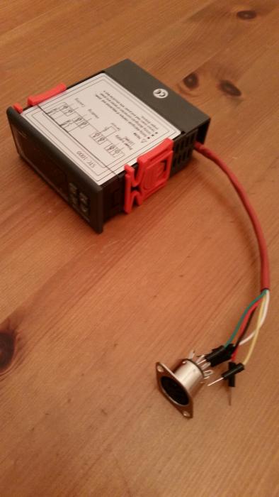
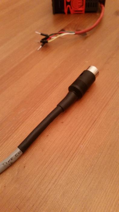
I soldered in a programming cable to the board using:
  • 5 Dupont wires soldered to circuit board and 5PIN F DIN connector. Cannot solder the wires until after I install the female DIN connector into the lid.
  • RJ45 cable (ends cut off, and used 5 of 8 available wires) soldered to the 5PIN M DIN connector.

I will eventually install the STC-1000 and the 5PIN F DIN connector into the lid of my chest freezer fermentation chamber which is currently controlled with a Control Products TC-9102D-HV Dual Stage High Voltage Digital Temperature Controller that works great but I am looking for the ramping ability of Alpha's awesome program.

I will post more pics hopefully this weekend.

20140617_225511.jpg


20140617_223206.jpg


20140617_230437.jpg
 
Last edited by a moderator:
Is there a place where I can buy a unit that has been flashed already? I don't feel like going through the DIY portion of this but I would like to replace the STC that is built in to the door of my ferm chamber. (I saw the Vendor post for the "black box" but don't need the whole assembly, just the STC). Thanks!
 
Is there a place where I can buy a unit that has been flashed already? I don't feel like going through the DIY portion of this but I would like to replace the STC that is built in to the door of my ferm chamber. (I saw the Vendor post for the "black box" but don't need the whole assembly, just the STC). Thanks!

I don't want to come off the wrong way here, but a home brewer that 'feel' like DIYing just seems plain wrong... It is a pretty easy procedure IMHO and well worth the effort. It is also not a bad thing to be able to upgrade your own controller when/if needed.
Now, I can understand if it an unfamiliar skillset, but if it is that unfamiliar, then you should probably not do the wiring yourself either.
Anyway, I'd sell anyone a controller at cost if I have any to spare, but shipment to the US would not be cost effective and I only have 220v ones.
If you really can't do it yourself, then I'm sure you could find someone on here that will flash your controller or sell one at markup if they have extras.
 
It is a pretty easy procedure IMHO and well worth the effort. It is also not a bad thing to be able to upgrade your own controller when/if needed.
Now, I can understand if it an unfamiliar skillset, but if it is that unfamiliar, then you should probably not do the wiring yourself either.

Agree with Alpha here, if you're comfortable doing the wiring, the flashing procedure won't be a challenge for you (and it's quick). I guess the only downside is that you'd need to buy an Arduino, but the upside is that you'd be able to update the firmware as improvements are made.

If you decide you'd really like to avoid doing the flashing, I'll do it for you for free if you cover the shipping to/from. (but by then you've spent $15-20, so you could just buy an Arduino :))
 
If anyone is interested, I just thought I'd give a quick 'status update'. I have done a little testing with using two temp probes and have gotten the swcond one working. The capacitor will need to be much less than what I posted previously or it will interfere with flashing. I don't yet know what value would be safe.
On the downside, there simply isn't any code space left to do anything useful with the second temp reading. I've been trying something very simple to start with, like just add a conditional to cut off when it is has reached a limit, but even that was too much..
So, right now I'm looking into trying to make some pretty gnarly optimizations to save code space, but I've been pretty diligent in writing the code in the first place, so it might not be so easy.
A cool thing is, that if you don't want to solder SMD, all the needed connections are on the programming header. So, if you have a connector for flashing, you could build a cable that has a normal resistor and capacitor and the probe. That way you could even use the larger cap as it is removed for flashing :)

Cheers!
 
If you decide you'd really like to avoid doing the flashing, I'll do it for you for free if you cover the shipping to/from. (but by then you've spent $15-20, so you could just buy an Arduino :))

I'll be an official flasher too...
flasher-smiley-emoticon.gif


A small flat rate box is like $6 bucks shipped in the lower 48. You must ensure that it is the correct version of STC-1000 before you ship it. Provide shipping both ways and I'll install a header and flash it with the latest.
 
I soldered in a programming cable to the board using:
  • 5 Dupont wires soldered to circuit board and 5PIN F DIN connector. Cannot solder the wires until after I install the female DIN connector into the lid.
  • RJ45 cable (ends cut off, and used 5 of 8 available wires) soldered to the 5PIN M DIN connector.

I will eventually install the STC-1000 and the 5PIN F DIN connector into the lid of my chest freezer fermentation chamber which is currently controlled with a Control Products TC-9102D-HV Dual Stage High Voltage Digital Temperature Controller that works great but I am looking for the ramping ability of Alpha's awesome program.

I will post more pics hopefully this weekend.


That looks pretty good. I just found those connectors on ebay for .99 each so I ordered 5 of each male/female with free shipping. Thanks!
 
Last edited by a moderator:
I'm sorry if this has been answered, but search function doesn't show me anything!
What was the issue with the S1000-POWER PCB boards in terms of getting them flashed? Was is a different MCU / different pin layout / something else?
 
Different MCU. With the only dataheet to be found written in chinese. Specs seem even less. Also it is missing the convenient programming header.
 
Why not just the ATmega168 - but that'll probably cost you more to buy singular than a pro-mini on ebay

I've got three Pro Mini's coming from Ebay for $2.33us ea and free shipping. I've got a specific project in mind with them (Auto Hop Dropper) but I might try and interface one to one of my non-flashable STC this winter. We'll see how bored I get.
 
Has anyone else had issues in uploading picprog to their Arduino? Depending on my luck (haven't found reliable way to make it work), I either get 'Upload complete' or 'Problem uploading to board'. Does anyone know of a decent thread to troubleshoot the failures?

Either way, after uploading (or attempting), I get:

Binary sketch size: 30,584 bytes (of a 32,256 byte maximum)
avrdude: stk500_recv(): programmer is not responding

The second line doesn't change regardless of if the upload completes or not - does anyone else get this?

One time (of 2) where I got upload complete, I connected the STC-1000 (lights up, displays the temp) hoping for signs of life. Opening the serial monitor, I didn't get the expected message. Sending 'd' doesn't get a response. The Uno can upload other sketches consistently it seems - 'Blink' works just fine, no messing around with the reset button required.

Any having/had something similar?
 
Has anyone else had issues in uploading picprog to their Arduino? Depending on my luck (haven't found reliable way to make it work), I either get 'Upload complete' or 'Problem uploading to board'. Does anyone know of a decent thread to troubleshoot the failures?

Either way, after uploading (or attempting), I get:

Binary sketch size: 30,584 bytes (of a 32,256 byte maximum)
avrdude: stk500_recv(): programmer is not responding

Did you copy only the picprog.ino to a picprog folder? The folder shouldnt have ANY other fies in it. I didnt do that the first time and was getting all kinds of weird errors.

Doesnt sound like this is the case with you but thought I'd throw it out there just in case.
 
Did you copy only the picprog.ino to a picprog folder? The folder shouldnt have ANY other fies in it.

The Arduino interface did that itself actually - as soon as I tried to open the sketch, I got a dialog box (as covered in the instructions), and the program made a folder 'picprog', and dropped the sketch in there.
 
It sounds like a communication issue. Arduino IDE (or really AVRDude) can't "talk" properly to the device.
Check that you have correct board (Tools->Board) and connection (Tools->Serial Port) selected in the Arduino IDE. If so, try another USB cable and/or port. Sometimes Arduino IDE can be fiddly when connecting/disconnecting USB.
 
Back
Top